Table of Contents
Advertisement
Quick Links
Advertisement
Table of Contents

Subscribe to Our Youtube Channel
Related Manuals for Jet J-7040M-4


Summary of Contents for Jet J-7040M-4
-
Page 1: Cover Page
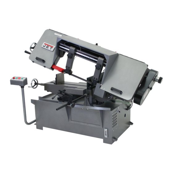
Operating Instructions and Parts Manual 10-inch x 16-inch Miter Cut-Off Band Saw Models: J-7020M, J-7040M, J-7040M-4 Model J-7020M shown 427 New Sanford Road LaVergne, Tennessee 37086 Part No. M-414474 Ph.: 800-274-6848 Revision C 01/2016 www.jettools.com Copyright © 2015 JET... -
Page 2: Warranty
JET sells through distributors only. The specifications listed in JET printed materials and on official JET website are given as general information and are not binding. JET reserves the right to effect at any time, without prior notice, those alterations to parts, fittings, and accessory equipment which they may deem necessary for any reason whatsoever. -
Page 3: Table Of Contents
Table of Contents Cover Page ..........................1 Warranty ............................2 Table of Contents .......................... 3 General Specifications ........................4 Warning ............................. 5-6 Introduction ..........................7 Miter Cut-Off Saw Features ......................7 Operating Instructions ....................... 7 Controls ............................7 Setting Blade Speed ........................8 Raising/Lowing Saw Head ...................... -
Page 4: General Specifications
General Specifications The JET Model J-7020M and J-7040M Miter Cut-off Saws cover a wide variety of applications in machine shops, maintenance shops, tool rooms, fabrication and welding shops, and almost any other application requiring a general purpose cut-off band saw. These models offer more standard features designed to provide maximum performance, greater accuracy and more economical operation. -
Page 5: Warning
Used properly , - Always be sure the machine support is se- JET machinery is among the best in design and curely anchored to the floor or the work bench. safety. However, any machine used improperly can be rendered inefficient and unsafe. - Page 6 20. Some dust created by power sanding, sawing, General Electrical Cautions grinding, drilling and other construction activities contains chemicals known to cause cancer, birth This saw should be grounded in accordance with defects or other reproductive harm. Some ex the National Electrical Code and local codes and amples of these chemicals are: ordinances.
-
Page 7: Introduction
This manual includes the operating and maintenance The operating controls for the saw are provided in instructions for the JET 10 X 16-inch Miter Cut-Off a control panel on the left side of the machine. The Saws, Models J-7020M and J-7040M. This manual control panel is mounted on a pivoting tube. -
Page 8: Setting Blade Speed
4. The feed rates on the placard are expressed in feet per minute. The feed rate graduations available on the indicator may not match the recommended feed rate. An approximate speed may therefore be required. For example, to set a speed rate of 130 feet per minute, the indicator would be set about midway between 100 feet- per-minute and 165 feet-per-minute graduations. -
Page 9: Controlling The Cut: Hydraulic Feed Control
This is usually on specific materials. However , the following proce- determined by observing the chip formation. (See dure will be adequate for break-in of JET -supplied Evaluating Blade Efficiency for more information on blades on lower alloy ferrous materials. -
Page 10: Work Set-Up
5. When the blade has completed about 1/3 of the 3. Loosen hex post to free moveable jaw . Position cut, increase the feed rate. Watch the chip the moveable jaw so it is parallel to and in contact formation until cutting is at its most efficient rate with the work piece. -
Page 11: Installation And Adjustment Of Work Stop
Installation and Adjustment of 5. Start the motor and allow the saw to come up to speed. Work Stop 6. Slowly set the saw down onto the workpiece. Adjust cutting speed with the feed rate control The work stop is used to set up the saw for valve. -
Page 12: Coolant Mixture And Quantity
Coolant Mixture and Quantity 1. Raise the saw head enough to allow the saw motor to operate. The general purpose coolant is a mixture of water 2. Loosen four knobs securing the blade cover . Lift soluble oil and water. Mix one part of soluble oil the cover and swing it backward. -
Page 13: Blade Guide Bearing Adjustment
This assures that the blade is not touching the 0.001 inch clearance between the blade and the shoulder of the wheel. guide bearings. The bearings will still turn freely with 11. Shut off the saw. this clearance. If the clearance is incorrect, the 12. -
Page 14: Test Cutting To Verify Adjustment Accuracy
4. Position the bearing by turning the bushing. Set The saw blade can be considered correctly adjusted the clearance at approximately 0.001 inch. The when the variation measure is no more than 0.012 blade should be in a vertical position between the inch across the face of the disk. -
Page 15: Lubrication
Lubrication 7. Adjust the bearings on the upper edge of the blade until they just cont act the blade (see figure 21). Lubricate the following components at the specified 8. Check the guide bearings and the carbide guides frequencies and using the lubricants defined below: to make sure they are just contacting the sides of 1. -
Page 16: Replacing The Drive Wheel
on the workpiece when the feed rate control valve is 5. Inspect bearings for damage and smooth opera- fully open. tion, Replace if faulty. 1. Raise the saw arm to its full upright position and 6. Install the bearing in the idler wheel. Install the lock it in position (refer to Figure 18). -
Page 17: Replacement Of Guide Bearings
Replacement of the Wire 1. Remove the cap screw and remove the carbide guide. Discard the carbide guide. Brush 2. Install the replacement carbide guide on the guide bearing support. Install the cap screw. Set the 1. Loosen four knobs securing the blade cover . Lift guide so it just contacts the side of the saw blade. -
Page 18: Electrical
Observe the following when connecting to the power source. (Refer to the wiring diagrams in Figures 23 - 26.) WARNING: JET RECOMMENDS THAT ANY HARD WIRING OF THE SAW TO A BRANCH, OR ANY CHANGE OF VOLTAGE SUPPLIED TO THE MOTOR BE PERFORMED BY A LICENSED ELECTRICIAN. - Page 19 115V - To reverse motor rotation switch terminal 5 and 6. 220V - To reverse motor rotation hook terminal 6 to 1. Figure 24: Connection diagram for 1ph motor Figure 25: Model 7040M cut-off saw wiring diagram Figure 26: Connection diagram for 3ph motor...
-
Page 20: Troubleshooting
Troubleshooting Probable cause Suggested remedy Fault 1. Material loose in vise. 1. Clamp work securely. Excessive blade 2. Incorrect speed or feed. 2. Check Machinist’s Handbook for breakage speed/feed appropriate for the material being cut. 3. Teeth too coarse for material. 3. -
Page 21: Replacement Parts
Blade is twisting 1. Blade is binding in the cut. 1. Decrease feed pressure. 2. Blade tension too high. 2. Decrease tension on blade Unusual wear on 1. Blade guides worn 1. Replace blade guides. side/back of blade 2. Blade guide bearings not adjusted. 2. - Page 23 Parts List - Model J-7020M/J-7040M Miter Cut-off Saw Base ITEM PART ITEM PART DESCRIPTION DESCRIPTION 5712441 Handle, Lock J-5507591G Base, Machine 5712421 Work Stop Bracket 5512197 Plug, Drain (3/8in, PT) 5712451 Stop, Work 5507592 Screw, Cap, 12 x 70 5712431 Rod, Work Stop 5507593 Nut, Hex, M12...
- Page 24 Parts List - Model J-7020M/J-7040M Miter Cut-off Saw Base ITEM PART ITEM PART DESCRIPTION DESCRIPTION 5507666 Plate, Motor Tilt 263-1 J-7020263-1 Screw, Pan Head, 92-1 TS-1490041 Bolt, Hex, M8 x 25 3/16" x 1/4" 5507667 Plate, Limit Switch J-7020264G Base, Box 5507668 Washer, Flat, M8 J-5521930G Sliding,Turn, Left...
- Page 26 Screw, 1/4 x 3/8 5519683M Model 7040, 2HP , 3P J-5507697G Cover, Blade Wheel 177-2 TS-1490081 Bolt, Hex, M8 x 45 146-1 5518109 Label, JET Logo 177-3 5507637 Washer, Lock, M8 146-2 5519511 Label, Blade Size 177-4 5507668 Washer, M8...
- Page 27 Parts List - Model J-7020M/J-7040M Miter Cut-off Saw Head ITEM PART ITEM PART DESCRIPTION DESCRIPTION 5713651 Washer, Spring, 1/4 261-1 5714041 Washer, 3/8" 5714161 Bolt, 1/4 x 1/2 261-2 5713081 Nut, Hex, 3/8" 5628371 Washer, Spring, 1/2 5714311 Connection, Head 5714181G 5714191 Screw, Cap, 1/2 x 3/4...
- Page 28 427 New Sanford Road LaVergne, Tennessee 37086 Ph.: 800-274-6848 www.jettools.com...
Need help?
Do you have a question about the J-7040M-4 and is the answer not in the manual?
Questions and answers