Table of Contents
Advertisement
Table of Contents
Chapter 1 Table of Contents
Chapter 1 Table of Contents..................................................................... 1
1.1 Disposal Instruction .....................................................................................4
1.2 A Thank-you Note Before You Get Start..........................................................6
1.3 Features of This Manual ...............................................................................7
1.4 Safety Information ......................................................................................7
Chapter 2 Introduction to This Motherboard ............................................... 8
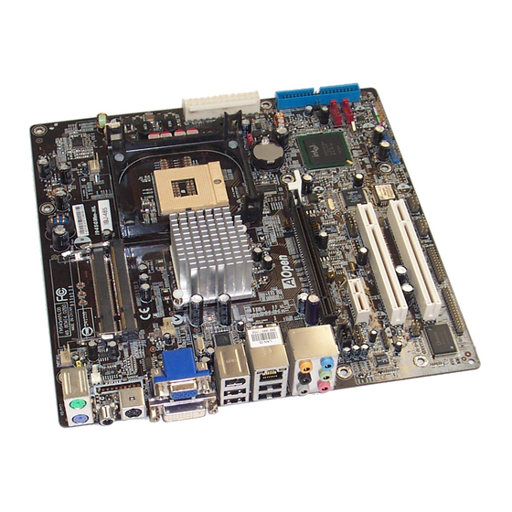
2.1 How does your motherboard look like?...........................................................8
2.2 Specification ...............................................................................................9
2.3 Block Diagram .......................................................................................... 10
Chapter 3 Hardware Installation ............................................................. 11
3.1 Quick Installation Procedure ....................................................................... 11
3.2 Installation You Have to Know..................................................................... 12
Installing CPU ...........................................................................................12
Installing CPU Cooler .................................................................................13
Installing CPU and System Fans ..................................................................16
Installing Memory Modules .........................................................................17
Maximum The Performance of the Dual Channel............................................18
Connecting IDE and Floppy Cables ..............................................................19
Connecting Front Panel Cable .....................................................................20
Connecting ATX Power Cables .....................................................................21
3.3 Other Installation for Your Reference ........................................................... 22
Setting CPU Frequency...............................................................................22
Connecting Serial ATA................................................................................23
Adjusting your Hard Disk Setting.................................................................24
Connecting PCI express x16 Graphics Slot ....................................................25
Connecting PCI Express x 1 Slot..................................................................27
Connecting IrDA........................................................................................28
1
Advertisement
Table of Contents

Subscribe to Our Youtube Channel
Related Manuals for AOpen i945GTm-VHL


Summary of Contents for AOpen i945GTm-VHL
-
Page 1: Table Of Contents
Table of Contents Chapter 1 Table of Contents Chapter 1 Table of Contents..............1 1.1 Disposal Instruction ..................4 1.2 A Thank-you Note Before You Get Start............6 1.3 Features of This Manual ................7 1.4 Safety Information ..................7 Chapter 2 Introduction to This Motherboard ..........8 2.1 How does your motherboard look like?............8 2.2 Specification ....................9 2.3 Block Diagram .................. - Page 2 10/100/1000Mbps LAN Supported ...............29 Connecting USB2.0..................30 Connecting 1394 ..................31 Super 7.1 Channel Audio Effect ..............32 Connecting Front Audio ................33 Connecting CD_IN ..................34 Connecting COM1/COM2 ................35 Connecting Case Open ................36 Connecting S/PDIF (Sony/Philips Digital Interface) ........37 3.4 Jumper Settings ..................38 Chapter 4 Special Features and Utilities...........
- Page 3 Exit without Saving ...................58 5.4 BIOS Upgrade under Windows environment..........59 Chapter 6 Installing Drivers ..............61 6.1 Installing Drivers..................62 6.2 Installing Utilities ..................64 6.3 Display output behavior ................65 Display output behavior ................66 Chapter 7 Troubleshooting..............67 Chapter 8 Technical Support ..............
-
Page 4: Disposal Instruction
For more information about the collection and recycling of Waste Electrical and Electronic Equipment (WEEE) , you are invited to visit our homepage at www.aopen.com under “Green Products”. Instruktion til bortskaffelse (Danish) Af hensyn til vores miljø bedes De ikke bortskaffe denne elektroniske enhed i en almindelig affaldsspand. - Page 5 För att minimera mängden föroreningar och så långt som möjligt skydda den globala miljön bör produkten återvinnas. För vidare information om insamling och återvinning av uttjänta elektriska och elektroniska produkter (Waste Electrical and Electronic Equipment, WEEE), besök avsnittet "Green Products" på vår hemsida, www.aopen.com.
-
Page 6: A Thank-You Note Before You Get Start
We regret not informing about any changes in usage standards and other related information. AOpen reserves the right of altering or modifying the content of this manual. In case of any mistakes or incorrect descriptions, which include those on the products, AOpen makes no guarantee or commitments. -
Page 7: Features Of This Manual
1.3 Features of This Manual To help you grab the useful information of this motherboard and aware of certain conditions that you might need to know, you will see the icons below frequently: Note This contains knowledge you should know in process of assembling, or some helpful tips. -
Page 8: Chapter 2 Introduction To This Motherboard
R5. 200 Pins SODIMM x 2 L6. FDD Connector R6. Marvell PCIe gigabit Lan Chip(i945GMm-HL) L7. Printer Connector R7. intel PCIe gigabit Lan(i945GTm-VHL) L8. 32-bit PCI Expansion slot x 2 R8. intel 945GT/945GM north bridge L9. PCI Express x1 Slot R9. -
Page 9: Specification
2.2 Specification Here is the main function of your motherboard. Models i945GTm-VHL I945GMm-HL intel Yonah Core Duo/Core Solo CPU Socket 479 533/667MHz intel 945GT/ICH7MDH intel 945GM/ICH7M Chipset Dual Channel DDRII SODIMM x 2, DDRII400/533 Main DIMM Type : 256/512MB & 1GB SODIMM... -
Page 10: Block Diagram
2.3 Block Diagram Socket 479 PCI Express x 1 500MB/s intel Yonah Slot x 1 Core VGA Onboard Duo/Solo PCI Bus 32-bit PCI Slot x 2 Standard Video 533/667MHz 150MB/s Serial ATA Port x 2 System 33/66/100 PCI Express x 16 IDE Drives x 2 Graphics Slot Intel... -
Page 11: Chapter 3 Hardware Installation
Chapter 3 Hardware Installation Chapter 3 Hardware Installation 3.1 Quick Installation Procedure 12. Installing Drivers & 1. Installing CPU Utilities 11. Installing Operating System 2. Installing CPU (such as, Windows Fan & System Fan 10. Loading Default BIOS, Setting CPU 3. -
Page 12: Installation You Have To Know
3.2 Installation You Have to Know Installing CPU This socket supports uFCPGA & uFCBGA package CPU, which is the latest Yonah Core Duo and Core Solo CPU package developed by Intel. Other forms of CPU package are impossible to be fitted in. Unscrew the socket screw counter-clockwise. -
Page 13: Installing Cpu Cooler
Installing CPU Cooler This motherboard comes with a special CPU cooler desiged by AOpen, please follow the following steps to install CPU cooler. Please apply thermal paste on the bottom of CPU cooler. Thermal paste Gently put CPU cooler onto the CPU retention module. - Page 14 Install two cooler fixing sticks into CPU retention module. Note: Make sure that the sticks have hooked retention module firmly. Fixing stick Push the iron plate of cooler fixing stick up a bit. Iron plate...
- Page 15 Then press iron plate downward till you hear a “clip” sound. Note: Make sure that the iron plate have hooked CPU retention module firmly.
-
Page 16: Installing Cpu And System Fans
Installing CPU and System Fans Plug the CPU fan cable to the 3-pin CPU FAN connector. If you have chassis fan, you can also plug it in SYSFAN2 connector. +12V Sensor POWER FAN Connector +12V Sensor System FAN Connector +12V Sensor CPU FAN Connector Note: Some CPU fans do... -
Page 17: Installing Memory Modules
Installing Memory Modules SODIMM slots are designed in high and low positions which are very easy to recognize. Insert the module straight down to the SODIMM slot with fingers and press down firmly until the SODIMM module is securely in place. Check the tabs are properly hold memory module... -
Page 18: Maximum The Performance Of The Dual Channel
When dual channel mode is successfully enabled, the screen will show “Dual Channel Mode Enabled” while entering POST screens. Phoenix - AwardBIOS v6.00PG Copyright (C) 1984-2003, Phoenix Technologies, LTD. i945GTm-VHL R1.00 Mar. 06. 2006 AOpen Inc. Main Processor : Intel(R) Pentium(R) M CPU T2500 @ 2.00GHz(166x12), 2 CPUs... -
Page 19: Connecting Ide And Floppy Cables
Connecting IDE and Floppy Cables Connect the 34-pin floppy cable and 40-pin, 80-wire IDE cable to floppy connector and IDE connector. Be careful of the pin1 orientation. Wrong orientation may cause system damage. Pin 1 FDD Connector Pin 1 Primary Primary Slave (2nd) Master (1st) -
Page 20: Connecting Front Panel Cable
Connecting Front Panel Cable Attach the power LED, speaker and reset switch connectors to the corresponding pins. If you enable “Suspend Mode” item in BIOS Setup, the ACPI & Power LED will keep flashing while the system is in suspend mode. Locate the power switch cable from your housing, which is a 2-pin female connector from the housing front panel. -
Page 21: Connecting Atx Power Cables
Connecting ATX Power Cables This motherboard comes with a 24-pin and 4-pin ATX power connector as shown below. Make sure you plug them in the right direction. We strongly recommend you to insert the 4-pin connector before connecting the 20-pin connector. +12V +12V Ground... -
Page 22: Other Installation For Your Reference
3.3 Other Installation for Your Reference Setting CPU Frequency Setting CPU Frequency This motherboard is CPU jumper-less design, you can set CPU frequency through 1MHz stepping CPU Overclocking in the BIOS. CPU Core Frequency = CPU External Frequency x CPU Ratio. However, all CPU now selling in the market belong to "Fixed Multiplier". -
Page 23: Connecting Serial Ata
Connecting Serial ATA To connect a serial ATA disk, you have to have a 7-pin serial ATA cable. Connect two ends of the serial ATA cable to the serial ATA header on the motherboard and the disk. Like every other traditional disk, you also have to connect a power cable. Please be noted that it is a jumper free implement;... -
Page 24: Adjusting Your Hard Disk Setting
Adjusting your Hard Disk Setting Except its original 1 set of parallel IDE, this motherboard supports the latest serial ATA hard disk. If you are unable to find your newly installed serial ATA hard disks on your operating system after having them installed, the problem may lie in the BIOS setting. -
Page 25: Connecting Pci Express X16 Graphics Slot
Connecting PCI express x16 Graphics Slot This motherboard provides a PCI Express x 16 Graphics slot, a black slot having the latest PCI Express x 16 specification on motherboard. The PCI Express x 16 is a bus interface targeted for high-performance 3D graphic. Traditionally AGP used both rising and falling edge of the 66MHz clock for 8X AGP, and the data transfer rate could achieve 2.1GB/s. - Page 26 If user plugs a PCI Express x 16 Graphics, you must remove jumpers beside PCI Express x 16 Slot. Plug PCI Express x16 graphic card, please remove jumpers below Remove Jumpers Warning: If user doesn’t remove jumper, it might make system unstable.
-
Page 27: Connecting Pci Express X 1 Slot
Connecting PCI Express x 1 Slot This motherboard provides one PCI Express x 1 slot, which is located between the PCI Express x 16 and traditional PCI slot. In order to go with the step of today’s and tomorrow’s processors, PCI Express x 1 provides higher I/O bandwidth. The transfer data rate could achieve 500MB/s concurrently (it’s 250MB/s per direction), which is nearly 4 times faster than the traditional PCI. -
Page 28: Connecting Irda
Connecting IrDA The IrDA connector can be configured to support wireless infrared module, with this module and application software such as Laplink or Windows Direct Cable Connection, user can transfer files to or from laptops, notebooks, PDA devices and printers. This connector supports both HPSIR (115.2Kbps, 2 meters) and ASK-IR (56Kbps). -
Page 29: 10/100/1000Mbps Lan Supported
10/100/1000Mbps LAN Supported On the strength of Marvell Gigabit LAN controller on board, this motherboard provides 10/100/1000Mbps Ethernet for office and home use. The Ethernet RJ45 connector is located on the top of USB connectors. The right hand side LED indicates link mode;... -
Page 30: Connecting Usb2.0
Connecting USB2.0 This motherboard provides eight USB 2.0 ports to connect USB devices such as mouse, keyboard, modem, printer, etc. There are four ports on the back panel. You can use proper cables to connect Front USB connector to USB modules or chassis front panel. -
Page 31: Connecting 1394
Connecting 1394 With IEEE1394 Chip on board (AGERE 1394), having its data transfer rate up to 400Mb/s, this interface can connect to devices that require high data transferring performance such as digital camera, scanner or others IEEE 1394 devices. Please use appropriate cables to connect IEEE1394 devices. -
Page 32: Super 7.1 Channel Audio Effect
Super 7.1 Channel Audio Effect This motherboard comes with an ALC882D CODEC, which supports the latest 7.1 Channel with high quality of audio effects, bringing you a brand new audio experience. This motherboard provides 7.1 Channel ports shown as below. Picture represents the standard location of all speakers in 7.1 Channel sound tracks. -
Page 33: Connecting Front Audio
Connecting Front Audio If the housing is designed with an audio port on the front panel, you’ll be able to connect onboard audio to front panel through this connector. By the way, please remove the jumper cap from the Front Audio Connector before you connect the cable. -
Page 34: Connecting Cd_In
Connecting CD_IN This connector is designed to connect CD Audio cable from CDROM or DVD drive to onboard sound. CD-IN Connector... -
Page 35: Connecting Com1/Com2
Connecting COM1/COM2 This motherboard provides two serial ports. All of them are on the left of PCI32 slot. With proper cable, you can connect it to the back panel of chassis. Pin 1 Pin 1 DCD# SOUT DTR# RTS# CTS#... -
Page 36: Connecting Case Open
Connecting Case Open The “CASE OPEN” header provides chassis intrusion-monitoring function. To make this function work, you have to enable it in the system BIOS, connect this header to a sensor somewhere on the chassis. So, whenever the sensor is triggered by lights or by the opening of the chassis, the system will beep to inform you. -
Page 37: Connecting S/Pdif (Sony/Philips Digital Interface)
Connecting S/PDIF (Sony/Philips Digital Interface) S/PDIF (Sony/Philips Digital Interface) is a newest audio transfer file format, which provides impressive audio quality through optical fiber and allows you to enjoy digital audio instead of analog audio. Through a specific converter, you can connect the S/PDIF connector to other end of the S/PDIF audio module, which bears S/PDIF digital input/output. -
Page 38: Jumper Settings
3.4 Jumper Settings This motherboard provides PS2 keyboard / mouse wake-up function. Disable (Default) Enable JP28 PS2 KB/Mouse Wakeup Jumper Normal Clear CMOS (Default) JP14 Clear CMOS Jumper You can clear CMOS to restore system default setting. To clear the CMOS, follow the procedure below. 1. -
Page 39: Chapter 4 Special Features And Utilities
Chapter 4 Special Features and Utilities Chapter 4 Special Features and Utilities 4.1 RAID (Redundant Array of Independent Disks) With intel Southbridge ICH7MDH implemented, i945GTm-VHL provides RAID 0 and RAID 1 function for the Serial ATA hard disks. Installation Raid driver under window installation... - Page 40 Press the “S” key to select “Specify Additional Device Please insert Raid Driver floppy Disk into Drive A: After Raid driver floppy disk insert properly in drive A, please “ENTER” to continue.
- Page 41 Please select “intel® 82801 GHM SATA RAID Controller (Mobile ICH7R/DH)” Press “enter” after selection. Please press “ENTER” to continue installation...
-
Page 42: Other Useful Features
4.2 Other Useful Features With excellent design ability of R&D team, AOpen boasts for its various powerful and handy features that come with our product like follows. You are welcomed visit technical website learn more about those features. http://english.aopen.com.tw/tech/techinside... -
Page 43: Chapter 5 Setting Bios
AOpen’s R&D engineering team had optimized most BIOS settings of this motherboard. However, some default settings of BIOS cannot fine-tune those sections that controlled by chipset. Therefore, this chapter is intended to guide you and help you to configure some other settings. -
Page 44: How To Use Phoenix-Award™ Bios Setup Program
5.2 How To Use Phoenix-Award™ BIOS Setup Program Generally, you can use arrow keys to highlight items that you want to choose, press <Enter> key to select, and use <Page Up> and <Page Down> keys to change setting values. You can press <Esc> key to quit Phoenix-Award™ BIOS setup program. -
Page 45: Standard Cmos Features
Standard CMOS Features The "Standard CMOS Setup" sets the basic system parameters such as the date, time, and the hard disk type. Use the arrow keys to highlight an item and <PgUp> or <PgDn> to select the value for each item. Standard CMOS Features >... - Page 46 IDE HDD Auto-Detection: Press “Enter” to auto-detect parameters of HDD IDE Channel 0 Master (Slave): Define the parameters of IDE devices in Channel 0 (Master or Slave). Available options: None: if there is no device, please select “None” for speeding boot up. Auto: enable BIOS to auto-detect parameters of IDE device.
-
Page 47: Advanced Bios Features
Advanced BIOS Features This screen appears when you select the option "Advanced BIOS Features" from the main menu. Advanced BIOS Features > Removable Device Priority Advanced BIOS Features > Hard Disk Boot Priority Advanced BIOS Features > CD-ROM Boot Priority This parameter allows you to specify the system boot up search sequence. -
Page 48: Advanced Chipset Features
Advanced Chipset Features The "Advanced Chipset Features" includes settings for the chipset dependent features. These features are related to system performance. Warning: Make sure fully understand the items contained in this menu before you try to change anything. You may change the parameter settings to improve system performance. -
Page 49: Integrated Peripherals
Integrated Peripherals This submenu appears if you select the option "Integrated Peripherals" from the main menu. This option allows you to configure the I/O features. Integrated peripherals > OnChip IDE Device Integrated peripherals > OnChip IDE Device > On-Chip Primary PCI IDE This item allows you to select work mode on PATA . - Page 50 Integrated peripherals > Onboard Device Integrated peripherals > Onboard Device > USB Controller Integrated Peripherals > Onboard Device > USB 2.0 Controller Integrated Peripherals > Onboard Device > USB keyboard Controller Integrated Peripherals > Onboard Device > Azalia/AC97 Audio Select Integrated Peripherals >...
- Page 51 Integrated peripherals > SuperIO Device This item allows you to set SuperIO device. Power ON Function: This item is used to select Wake on Keyboard/Mouse mode. Password: Disable the function of power button and let the system can only be powered on through the preset keys (like a password). Hot Key: If selecting this option, you also need to specify the hot key from “Hot Key Power On”...
- Page 52 Onboard Serial Port 2: This item allows you to assign address and interrupt for the board serial port. The default is “Auto”. UART Mode Select: This item is configurable only if the "Onboard Serial Port 2" is enabled. This allows you to specify the mode of serial port2. Available options: Normal: Sets serial port 2 to operate in normal mode.
-
Page 53: Power Management Setup
Power Management Setup The Power Management Setup screen enables you to control the motherboard green features. See the following screen. Power Management > ACPI Suspend Type This function allows you to select suspend types. S1 is Power On Suspend and S3 is Suspend to RAM. - Page 54 Power Management > USB KB wake-up From S3 The USB KB wake-up from S3 support USB Keyboard wake up under S3 mode Available options: Disabled, Enabled Power Management > Resume by Alarm This function can provide alarm to resume system immediately. Available options: Disabled, Enabled Power Management >...
-
Page 55: Pc Health Status
PC Health Status The PC Health Status can bring PC important safety parameters for detect Health of your system. PC Health Status > CPU Smart Fan The CPU smart fan can detect CPU temperature and adjust fan speed automatically. That can ensure you to have silent & best working environment for system. -
Page 56: Frequency/Voltage Control
Frequency/Voltage Control This submenu allows you to configure the CPU and memory clock. Frequency/Voltage Control > Spread Spectrum This item is used to set the value of clock Spread Spectrum. BIOS will determine the adjustable value according to the CPU installed, not all items will be showed. Available options: Disabled, Enabled Frequency/Voltage Control >... -
Page 57: Load Optimized Defaults
Load Optimized Defaults The "Load Optimized Defaults" option loads BIOS default settings. Set Supervisor Password Supervisor Password prevents unauthorized use of your computer. If you set a password, the system prompts for the correct password before boot or access to Setup. -
Page 58: Set User Password
Set User Password User Password can authorize users check only. It cannot modify the BIOS setting inside. The item just allow take a look defult value on BIOS inside. To set a password: At the prompt, type your password. Your password can be up to 8 alphanumeric characters. -
Page 59: Bios Upgrade Under Windows Environment
5.4 BIOS Upgrade under Windows environment With outstanding R&D ability of AOpen, we now bring you a whole new BIOS Flash wizard ---- EzWinFlash. With an eye to convenience for users, EzWinFlash combines the BIOS binary code and flash module together, so the only thing you have to do is just clicking on the utility you downloaded from web and let it help you complete the flash process automatically. - Page 60 STRONGLY RECOMMENDED to close all applications before you start the upgrades. Download the latest version of BIOS package zip file from AOpen official web site. (Ex: http://english.aopen.com.tw/) Unzip the downloaded BIOS package (ex: WSGMAXII102.ZIP) with WinZip (http://www.winzip.com) in Windows environment.
-
Page 61: Chapter 6 Installing Drivers
Click and done. Yes. EzInstall makes installation easy and even foolproof! After putting in the CD, you will be prompted with AOpen welcome page and our branches information. First, click on the install driver ICON at left side for necessary drivers. -
Page 62: Installing Drivers
6.1 Installing Drivers As you may see from the Installing driver page, EzInstall had picked up necessary for your motherboard. All you have to do is just click on the “GO”, and no more steps afterward, of all listed drivers, grey checks indicate necessary drivers; you cannot click them off. - Page 63 After installed the driver successfully, the system configuration of your system can be checked through the Window Device Manager. There should not have any warning sign on each red frame below. That means your driver work successful now.
-
Page 64: Installing Utilities
6.2 Installing Utilities Installing Utilities is virtually the same as installing drivers. AOpen provides you many friendly and powerful utilities to manage your system. You may find lots of fabulous utilities listed there, and all you have to do is to click on the “GO”, then it will install the utilities to your system right away without complicated steps. -
Page 65: Display Output Behavior
6.3 Display output behavior AOpen provides newest innovation with high definition display output. Below diagram will show the way of display output. D-SUB YPbPr S-Video LCD with DVI Connector TV/HDTV TV/SDTV (1) Intel Drive just supports “Dual Monitor Mode” and “Single Monitor Mode”. -
Page 66: Display Output Behavior
Display output behavior Output Mode During POST VGA initial YpbPr / Output Connector D-SUB S-Video Output Device TV 1 Combination D-SUB YPbPr / S-Video D-SUB+DVI D-SUB+YPbPr / S-Video D-SUB+DVI+YPbPr / S-Video DVI+YPbPr / S-Video Output Mode Windows Platform YpbPr / Output Connector D-SUB S-Video... -
Page 67: Chapter 7 Troubleshooting
Chapter 7 Troubleshooting Chapter 7 Troubleshooting... -
Page 68: Chapter 8 Technical Support
Gold Member of Club AOpen so as to ensure quality service in the future. In order to maintain the best service to every customer of us, we recommend you to follow the procedures below and seek help from our branches according to the region you buy the product. -
Page 69: Model Name And Bios Version
Gold member of Club AOpen, and to ensure high service quality and priority from AOpen. You will also have a chance to play slot machine game to win prize from AOpen. Please prepare the following information before you start: Model Name, Part Number (P/N), Serial Number (S/N) and Purchase Date. -
Page 70: Technical Support
Technical Support...
Need help?
Do you have a question about the i945GTm-VHL and is the answer not in the manual?
Questions and answers