Table of Contents
Advertisement
Table of Contents
Table of Contents
Table of Contents ................................................................................... 1
1.1 Thank-you Note Before You Get Start.............................................................3
1.2 Features of This Manual ...............................................................................4
1.3 Safety Information ......................................................................................4
Chapter 2 Introduction to This Motherboard ............................................... 5
2.1 How does your motherboard look like?...........................................................5
2.2 Specification ...............................................................................................6
2.3 Block Diagram ............................................................................................7
Chapter 3 Hardware Installation ............................................................... 8
3.1 Quick Installation Procedure .........................................................................8
3.2 Installation You Have to Know.......................................................................9
Installing CPU ............................................................................................ 9
Installing CPU Fan .....................................................................................10
Connecting CPU and System Fans ...............................................................11
Installing Memory Modules .........................................................................12
Maximum The Performance of the Dual Channel............................................13
Connecting IDE and Floppy Cables ..............................................................14
Connecting Front Panel Cable .....................................................................15
Connecting ATX Power Cables .....................................................................16
3.3 Other Installation for Your Reference ........................................................... 17
Setting CPU Voltage and Frequency .............................................................17
Connecting Serial ATA................................................................................18
Adjusting your Hard Disk Setting.................................................................19
Connecting PCI Express x 16 Graphics Slot...................................................21
Connecting PCI Express x 1 Slot..................................................................22
Connecting IrDA........................................................................................23
10/100/1000Mbps LAN Supported (1000Mbps Only for i915Gm-IE) .................24
1
Advertisement
Table of Contents

Related Manuals for AOpen i915Gm-IE


Summary of Contents for AOpen i915Gm-IE
-
Page 1: Table Of Contents
3.3 Other Installation for Your Reference ............17 Setting CPU Voltage and Frequency .............17 Connecting Serial ATA................18 Adjusting your Hard Disk Setting..............19 Connecting PCI Express x 16 Graphics Slot...........21 Connecting PCI Express x 1 Slot..............22 Connecting IrDA..................23 10/100/1000Mbps LAN Supported (1000Mbps Only for i915Gm-IE) ....24... - Page 2 Connecting USB2.0..................25 Super 7.1 Channel Audio Effect ..............26 Connecting Front Audio ................27 Connecting Game Port ................28 Connecting COM2..................29 Connecting CD_IN ..................30 Connecting Case Open ................31 Colored Coded Back Panel ................32 LED Indication ..................33 3.4 Jumper Settings ..................34 Chapter 4 Special Features and Utilities........... 35 SilentTek –...
-
Page 3: Thank-You Note Before You Get Start
We regret not informing about any changes in usage standards and other related information. AOpen reserves the right of altering or modifying the content of this manual. In case of any mistakes or incorrect descriptions, which include those on the products, AOpen makes no guarantee or commitments. -
Page 4: Features Of This Manual
1.2 Features of This Manual To help you grab the useful information of this motherboard and aware of certain conditions that you might need to know, you will see the icons below frequently: Note This contains knowledge you should know in process of assembling, or some helpful tips. -
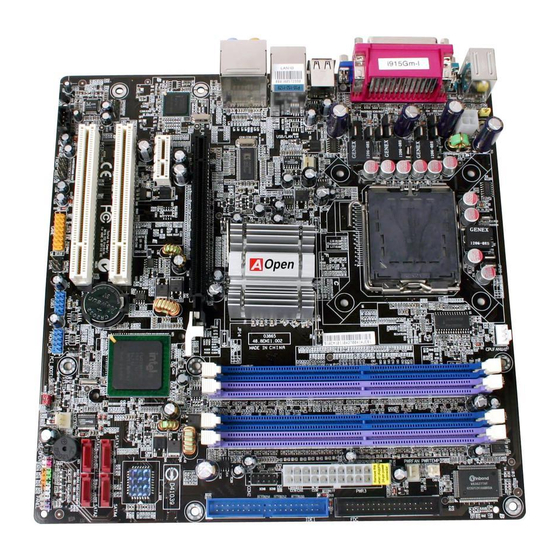
Page 5: Chapter 2 Introduction To This Motherboard
25. BOOT LED 11. FDD Connector 26. SYSFAN2 Connector 12. IDE Connector 27. Case Open Connector 13. Intel Gigabit LAN Chip (i915Gm-IE) 28. Front Panel Connector Intel 10/100Mbps LAN Chip (i915Gm-I) 14. PCI Express x 1 Slot 29. COM2 Connector 15. -
Page 6: Specification
2.2 Specification Here is the main function of your motherboard. Models i915Gm-IE i915Gm-I Intel FC-LGA4 CPU Intel FC-LGA4 CPU Socket T Socket T 800MHz 800MHz Chipset Intel 915G/ICH6 Intel 915G/ICH6 Dual Channel Mode DDR Dual Channel Mode DDR DDR 333/400... -
Page 7: Block Diagram
2.3 Block Diagram PCI Express x 1 Slot PCI Bus 32-bit PCI Slots LGA775 Socket Intel FC-LGA4 150MB/s Serial ATA Ports 533/800 MHZ ATA 33/66/100 System Bus IDE Drives x 2 VGA Onboard Intel 915G HD Audio chipset PCI Express x 16 CODEC Graphics Slot Support ADD2 Card... -
Page 8: Chapter 3 Hardware Installation
Chapter 3 Hardware Installation Chapter 3 Hardware Installation 3.1 Quick Installation Procedure 12. Installing Drivers & 1. Installing CPU Utilities 11. Installing Operating System 2. Installing CPU (such as, Windows Fan & System Fan 10. Loading Default BIOS, 3. Installing Setting CPU Memory Module Frequency... -
Page 9: Installation You Have To Know
3.2 Installation You Have to Know Installing CPU This socket supports FC-LGA4 CPU, which is the latest CPU package developed by Intel. Other forms of CPU package are impossible to be fitted in. Pull CPU socket lever and plate up. Remove plastic cap from CPU socket plate. -
Page 10: Installing Cpu Fan
Installing CPU Fan 1. Gently put down the CPU fan on CPU socket with four sticks aiming correctly to the four mounting holes. Mounting Mounting hole hole 2. Press down four fixing sticks into the holes one by one. Make sure the sticks are firmly fixed into the holes. -
Page 11: Connecting Cpu And System Fans
Connecting CPU and System Fans Plug the CPU fan cable to the 4-pin CPUFAN connector. If you have chassis fan, you can also plug chassis fan in SYSFAN1 or SYSFAN2 connector. +12V SENSOR SYSFAN1 Connector SENSOR +12V +12V CPUFAN Connector SENSOR SYSFAN2 Connector Note: Some CPU fans... -
Page 12: Installing Memory Modules
Installing Memory Modules DIMM slots are designed in Navy Blue and Electronic Blue which are very easy to recognize. Insert the module straight down to the DIMM slot with both hands and press down firmly until the DIMM module is securely in place. Pin 1 Note: The tabs of the DIMM slot will clip to hold the... -
Page 13: Maximum The Performance Of The Dual Channel
Maximum The Performance of the Dual Channel o obtain the highest performance of Dual Channel, the configuration of DIMM must meet the following conditions. Matched DIMM configuration in each channel ● Same density (128MB~1GB) As long as you insert memory modules of same density into Channel 1 (DIMM A1 &... -
Page 14: Connecting Ide And Floppy Cables
Connecting IDE and Floppy Cables Connect the 34-pin floppy cable and 40-pin, 80-wire IDE cable to floppy connector and IDE connector. Be careful of the pin1 orientation. Wrong orientation may cause system damage. FDD Connector Pin 1 Pin 1 Primary Primary Slave (2nd) Master (1st) -
Page 15: Connecting Front Panel Cable
Connecting Front Panel Cable Attach the power LED, speaker and reset switch connectors to the corresponding pins. If you enable “Suspend Mode” item in BIOS Setup, the ACPI & Power LED will keep flashing while the system is in suspend mode. Locate the power switch cable from your ATX housing, which is a 2-pin female connector from the housing front panel. -
Page 16: Connecting Atx Power Cables
Connecting ATX Power Cables This motherboard comes with a 24-pin ATX power connector and 4-pin 12V ATX power connector as shown below. Make sure you plug them in the right direction. We strongly recommend you to insert the 4-pin connector before connecting the 24-pin connector. -
Page 17: Other Installation For Your Reference
3.3 Other Installation for Your Reference Setting CPU Voltage and Frequency Setting CPU Core Voltage This motherboard supports Voltage ID (VID) function to detect CPU voltage automatically during power-on and the range is from 0.8375V to 1.6V. It’s not necessary to set CPU core voltage. Setting CPU Frequency This motherboard is CPU jumper-less design;... -
Page 18: Connecting Serial Ata
Connecting Serial ATA To connect a serial ATA disk, you have to have a 7-pin serial ATA cable. Connect two ends of the serial ATA cable to the serial ATA header on the motherboard and the disk. Like every other traditional disk, you also have to connect a power cable. Please be noted that it is a jumper free implement;... -
Page 19: Adjusting Your Hard Disk Setting
Adjusting your Hard Disk Setting Except its original 1 set of parallel IDE, this motherboard supports the latest serial ATA hard disk. If you are unable to find your newly installed serial ATA hard disks on your operating system after having them installed, the problem may lie in the BIOS setting. - Page 20 If you desire to change the default setting, press Enter for selection list: Disabled: You can choose this item if there are only traditional IDE hard disks had been installed on your system. Disabling this item will also cancel the detection of serial ATA hard disks during POST, which will theoretically speed up your boot-up time a little bit;...
-
Page 21: Connecting Pci Express X 16 Graphics Slot
Connecting PCI Express x 16 Graphics Slot i915Gm-IE / i915Gm-I provides a PCI Express x 16 Graphics slot, a white slot having the latest PCI Express x 16 specification on motherboard. The PCI Express x 16 is a bus interface targeted for high-performance 3D graphic. Traditionally AGP used both rising and falling edge of the 66MHz clock for 8X AGP, and the data transfer rate could achieve 2.1GB/s. -
Page 22: Connecting Pci Express X 1 Slot
Connecting PCI Express x 1 Slot This motherboard provides one PCI Express x 1 slot, which is located between the PCI Express x 16 and traditional PCI slot. In order to go with the step of today’s and tomorrow’s processors, PCI Express x 1 provides higher I/O bandwidth. The transfer data rate could achieve 500MB/s concurrently (it’s 250MB/s per direction), which is nearly 4 times faster than the traditional PCI. -
Page 23: Connecting Irda
Connecting IrDA The IrDA connector can be configured to support wireless infrared module, with this module and application software such as Laplink or Windows Direct Cable Connection, user can transfer files to or from laptops, notebooks, PDA devices and printers. This connector supports both HPSIR (115.2Kbps, 2 meters) and ASK-IR (56Kbps). -
Page 24: 10/100/1000Mbps Lan Supported (1000Mbps Only For I915Gm-Ie)
10/100/1000Mbps LAN Supported (1000Mbps Only for i915Gm-IE) On the strength of Gigabit LAN controller on board, this motherboard provides 10/100/1000Mbps (10/100Mbps is for i915Gm-I) Ethernet for office and home use. The Ethernet RJ45 connector is located on the top of USB connectors. The right hand side LED indicates link mode;... -
Page 25: Connecting Usb2.0
Connecting USB2.0 This motherboard provides eight USB 2.0 ports to connect USB devices such as mouse, keyboard, modem, printer, etc. There are four ports on the back panel. You can use proper cables to connect Front USB connector to USB modules or chassis front panel. -
Page 26: Super 7.1 Channel Audio Effect
Super 7.1 Channel Audio Effect This motherboard comes with an ALC880 CODEC, which supports the latest 7.1 Channel with high quality of audio effects, bringing you a brand new audio experience. This motherboard provides 7.1 Channel ports shown as below. Picture represents the standard location of all speakers in 7.1 Channel sound tracks. -
Page 27: Connecting Front Audio
Connecting Front Audio If the housing is designed with an audio port on the front panel, you’ll be able to connect onboard audio to front panel through this connector. Please be informed that to have front audio ports work properly, the front audio panel of the housing should be designed for High definition Audio jack. -
Page 28: Connecting Game Port
Connecting Game Port This motherboard comes with a game port (Joystick-Midi) for you to connect any midi devices or joysticks. To use this function you have to have a joystick module and connect it with a game port cable to this port on the motherboard. Pin1 (User Upgrade Optional) -
Page 29: Connecting Com2
Connecting COM2 This motherboard provides two serial ports. One of them is on back panel connector, and the other is on the left side of EPS power connector. With proper cable, you can connect it to the back panel of chassis. Pin 1 SOUT RTS#... -
Page 30: Connecting Cd_In
Connecting CD_IN This connector is designed to connect CD Audio cable from CDROM or DVD drive to onboard sound. CD-IN Connector... -
Page 31: Connecting Case Open
Connecting Case Open The “CASE OPEN” header provides chassis intrusion-monitoring function. To make this function work, you have to enable it in the system BIOS, connect this header to a sensor somewhere on the chassis. So, whenever the sensor is triggered by lights or by the opening of the chassis, the system will beep to inform you. -
Page 32: Colored Coded Back Panel
Colored Coded Back Panel The onboard I/O devices have PS/2 Keyboard, PS/2 Mouse, RJ-45 LAN Connector, COM1, VGA port, Printer, USB, Azalia sound and game ports. The view angle of drawing shown here is from the back panel of the housing. SPP/EPP/ECP Rear SUR RJ45... -
Page 33: Led Indication
LED Indication LED indication including Boot LED and Standby LED are AOpen’s considerate designs that aim at providing you friendly system information. STBY LED will light up when power is provided to the motherboard, giving you a convenient indication check the system power status in circumstances such as power on/off, stand-by mode and RAM power status during Suspend to RAM mode. -
Page 34: Jumper Settings
3.4 Jumper Settings This motherboard provides PS2 keyboard / mouse JP28 Keyboard / Mouse wake-up function. Wakeup Jumper JP28 KB/Mouse Wakeup Jumper Disable Enable (Default) JP14 Clear CMOS Jumper Normal Clear CMOS (default) You can clear CMOS to restore system default setting. To clear the CMOS, follow the procedure below. -
Page 35: Chapter 4 Special Features And Utilities
Today, AOpen Motherboard is honored to bring you a new overall solution, SilentTek, to make your system quiet. To collocate with hardware circuit, BIOS and the utility under Windows, SilentTek combines “Hardware-Status Monitoring”,... - Page 36 The first image you have here is Voltage Status page. You can find current status of all voltages here and set your expected margins of warning level. You may check your system voltage from the indicating bar here. In “Temp/Fan/Case” page, you can get aware of the current temperature of CPU and the heat inside chassis.
- Page 37 Smart FAN Control: This is the default setting of SilentTek and can be used for any branded computer housing. With a special algorithm developed by AOpen, the fan speed is automatically adjusted by the parameters of CPU and ambient temperature which is ease-of-use and trouble free at your service.
-
Page 38: Other Useful Features
Other Useful Features With excellent design ability of R&D team, AOpen boasts for its various powerful and handy features that come with our product like follows. You are welcomed visit technical website learn more about those features. http://english.aopen.com.tw/tech/techinside... -
Page 39: Chapter 5 Setting Bios
AOpen’s R&D engineering team had optimized most BIOS settings of this motherboard. However, some default settings of BIOS cannot fine-tune those sections that controlled by chipset. Therefore, this chapter is intended to guide you and help you to configure some other settings. -
Page 40: How To Use Phoenix-Award™ Bios Setup Program
How To Use Phoenix-Award™ BIOS Setup Program Generally, you can use arrow keys to highlight items that you want to choose, press <Enter> key to select, and use <Page Up> and <Page Down> keys to change setting values. You can press <Esc> key to quit Phoenix-Award™ BIOS setup program. -
Page 41: Bios Upgrade Under Windows Environment
BIOS Upgrade under Windows environment With outstanding R&D ability of AOpen, we now bring you a whole new BIOS Flash wizard ---- EzWinFlash. With an eye to convenience for users, EzWinFlash combines the BIOS binary code and flash module together, so the only thing you have to do is just clicking on the utility you downloaded from web and let it help you complete the flash process automatically. - Page 42 STRONGLY RECOMMENDED to close all applications before you start the upgrades. Download the latest version of BIOS package zip file from AOpen official web site. (Ex: http://english.aopen.com.tw/) Unzip the downloaded BIOS package (ex: WSGMAXII102.ZIP) with WinZip (http://www.winzip.com) in Windows environment.
-
Page 43: Vivid Bios Technology
Have you been fed up with the conservative and immutable POST screen? Let’s rule out the tradition idea that POST screen are stiff and frigid, and let AOpen show you the newly developed VividBIOS to experience the lively vivid colorful... -
Page 44: Chapter 6 Installing Drivers
Click and done. Yes. EzInstall makes installation easy and even foolproof! After putting in the CD, you will be prompted with AOpen welcome page and our branches information. First, click on the install driver ICON at left side for necessary drivers. -
Page 45: Installing Drivers
6.1 Installing Drivers As you may see from the Installing driver page, EzInstall had picked up necessary for your motherboard. All you have to do is just click on the “GO”, and no more steps afterward, of all listed drivers, grey checks indicate necessary drivers; you cannot click them off. -
Page 46: Installing Utilities
6.2 Installing Utilities Installing Utilities is virtually the same as installing drivers. AOpen provides you many friendly and powerful utilities to manage your system. You may find lots of fabulous utilities listed there, and all you have to do is to click on the “GO”, then it will install the utilities to your system right away without complicated steps. -
Page 47: Chapter 7 Troubleshooting
Chapter 7 Troubleshooting Chapter 7 Troubleshooting... -
Page 48: Chapter 8 Technical Support
Gold Member of Club AOpen so as to ensure quality service in the future. In order to maintain the best service to every customer of us, we recommend you to follow the procedures below and seek help from our branches according to the region you buy the product. -
Page 49: Model Name And Bios Version
Gold member of Club AOpen, and to ensure high service quality and priority from AOpen. You will also have a chance to play slot machine game to win prize from AOpen. Please prepare the following information before you start: Model Name, Part Number (P/N), Serial Number (S/N) and Purchase Date. -
Page 50: Technical Support
Technical Support...
Need help?
Do you have a question about the i915Gm-IE and is the answer not in the manual?
Questions and answers