Advertisement
Quick Links
Cool Stuff is Hot Stuff, MoDT is the Right Stuff
mini ITX i945GCt
Enable the Power of mini ITX Form Factor
Accessories List
DC Adaptor
IO Bracket
HDD S-ATA Cable
AOpen Bonus CD
& Power Cord
mini ITX i945GCt EIG
Power Cord
ODD S-ATA Cable
Power Cable
& Power Cord
AOpen reserves the right to revise all the specifications and information contained in this document, which are subject to change without notice.
Installing Memory Module
The motherboard provide long DIMM type memory support. The installation
of memory module as below.
1. Put the memory module with correct direction. Notice there's one stick to
make sure direction is correct.
2. There're tabs which located in the side of long DIMM holder. Use finger to
push memory module vertically until the tabs lock memory module tightly.
3. Now, the memory modules have been plugged properly with horizontal flat.
Installing ODD & HDD Device
The mother board provides three SATA connectors.
Connect SATA cable to the on board SATA connector. You can find SATA
cable in our package. (this is SATA signal cable) And please also connect
5V power connector with SATA power cable.
SATA Signal Cable To
HDD
Connect SATA Device
SATA Power Cord To
Connect SATA Device
ODD
Part No.: 49.8ET0A.EE10 Doc. No.: I945GCT-EG-E0809A
MoDT is initiated by AOpen since 2004
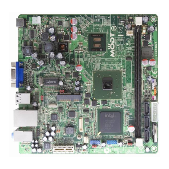
19V DC Adaptor
Connector
Front Audio Connector
JP1
J1
PCI-E x 1 Slot
Mini Card Connector
SYSTEM Fan Connector
JP2
USB 2.0 Connector x 2
Intel Sourth Bridge ICH7
JP14
Long Dimm Slot (DDRII)
SATA2 Connector x 3
Battery
4 Pin DC Power Output Connector
Note:
Jumper Setting
J1:
Mini card support wack up from S3.
1-2 Enable wack up from S3 (Default)
2-3 Disable wack up from S3
JP1 JP2:
USB port support wack up from S3.
1-2 Disable wack up from S3
2-3 Enable wack up from S3
JP14 Clear CMOS
You can clear CMOS to restore system default settings.
To clear the CMOS, follow the procedure below.
1. Turn off the system and unplug the DC Adaptor from Connector.
2. Locate JP14 and short pins 2-3 for a few seconds.
3. Return JP14 to its normal setting by connecting it to Pin 1-2 again.
4. Connect DC Adaptorn back to connector.
JP14 Clear CMOS Jumper
Clear CMOS
VGA Port
USB 2.0 Ports
The images might look different according to the product.
1
Normal (Default)
(Default)
1
Normal (Default)
1
1
Normal (Default)
Tip: When should I clear CMOS?
1. Boot fail .....
2. Forget password .....
3. Trouble shooting .....
RJ45 LAN Jack
Line In / SPDIF Out
Speaker Out
MIC-In
DC In Power
Connector
DC In Connector
(Option), Support
Customzation Cable
ATOM 330
Intel North Bridge
945GC
NBFAN Connector
Front Panel
Connector
Mini Card Installation
The motherboard provides one Mini
Card slot for users to upgrade his
PC functions. Now, the Mini Card
can have digital TV tuner and Video
MPEG4 decoder card ...etc. for
expansion. The PCI cards have
SATA II and Firewire and USB
cards ... etc. for expansion.
Example
1. MPEG4 encoder
2. TV Tuner Mini Card
Advertisement

Subscribe to Our Youtube Channel
Related Manuals for AOpen MODT i945GCt


Summary of Contents for AOpen MODT i945GCt
- Page 1 The images might look different according to the product. Power Cable & Power Cord AOpen reserves the right to revise all the specifications and information contained in this document, which are subject to change without notice. Installing Memory Module Jumper Setting Mini Card Installation The motherboard provide long DIMM type memory support.
- Page 2 If you encounter any trouble to boot you system, follow the procedures accordingly to resolve the problem. Thanks for choosing AOpen products. In order to maintain the best service to every customer of us, we recommend you to follow the procedures below and seek help from our branches according to the region you buy the product.
Need help?
Do you have a question about the MODT i945GCt and is the answer not in the manual?
Questions and answers