
Related Manuals for Emerson ZX


Summary of Contents for Emerson ZX
-
Page 1: Condensing Unit
OUTDOOR REFRIGERATION CONDENSING UNIT USER MANUAL Emerson Climate Technologies (Suzhou) Co., Ltd. -
Page 2: Table Of Contents
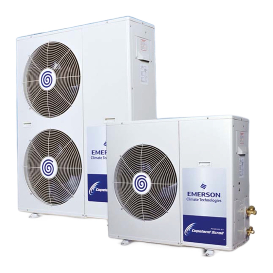
CONTENTS Section Item Page No. Disclaimer Introduction to the ZX Refrigeration Condensing Unit (CDU) 2.1 Product Description 2.2 Basic and Optional Configurations 2.3 Control Features 2.4 Diagnostic and Defrost Features 2.5 Advantages 2.6 ZX Value Story 2.7 Application Types Nomenclature... - Page 3 LIST OF ILLUSTRATIONS Page No. Fig.1 ZX Single Fan Unit (ZX200, ZX300 & ZX400) Fig.2 ZX Dual Fan Unit ( ZX 500, ZX600 & ZX 750) Fig.3 E2 Control Board Fig.4 The Defrost Module Fig.5 The Diagnostic Module Fig.6 The Diagnostics Interpretation Chart Fig.7...
-
Page 4: Disclaimer
These instructions are general in nature for this family of products (ZX) and due to our policy of continuous improvement some of the detail may not apply to the unit you are installing. -
Page 5: Introduction To The Zx Refrigeration Condensing Unit (Cdu)
R404A Refrigerants. The Single Fan units are ZX 200, ZX 300 and ZX 400 (2, 3 and 4 hp nominal ARI MT) and the Dual Fan units are ZX 500 , ZX 600 and ZX 750 ( 5,6 and 7.5 hp nominal ARI MT). - Page 6 ZX is a very affordably designed CDU. With a large Coil, small Fan design coupled with Built-In Fan Speed Control (Optional), the ZX is one of the Quietest Refrigeration CDU on the market.
-
Page 7: Basic And Optional Configurations
Fig 3. The E2 Control Board 2.2 Basic and Optional Configuration The ZX is marketed with both a Basic configuration and a Basic plus additional Option Package. The Basic ZX CDU consists of a Chassis, Condenser Coil and Fan/s, Electronic Control... -
Page 8: The Defrost Module
Fig 4. The Defrost Module Fig 5. The Diagnostic Module (now available without Buzzer ) -
Page 9: Control Features
2.3 Control Features As mentioned earlier, the ZX CDU Control System evolves around the E2 Board and one of it’s primary functions is the Automatic Liquid Injection system that ensures that the ZX Compressor operates within a safe envelope. This is carried out with an injection of Liquid Refrigerant Into the Scroll Suction, this process has a global patent on it. -
Page 10: Diagnostic And Defrost Features
2.4 Diagnostic and Defrost Features The Diagnostic Module (Option) is also installed within the Chassis and has a 5 LED’s (Light Emitting Diodes ) that can either be ON, OFF or BLINKING. The Combination of these 5 LED’s with these 3 different LED status can provide the different system status as shown in Fig 6 below : Fig 6. -
Page 11: Advantages
Withstand Substantial Liquid Floodback (Scroll Set) and finally a High Efficiency ( EER @ ARI MT Rating Between 2.4 To 2.75) 2.6 The ZX Value Story The Value of the ZX CDU based on the above can be summarized in to the Key Value Points as... - Page 12 Fan Speed Control – Low Sound Level and Lower Energy Consumption Ventilation – Easy To Retrofit For Discharge Air Extraction Machine Room Saving – Eliminate Wasteful Space, Mount The ZX On The Wall The following explains why the ZX is more Energy Efficient: Scroll Compressor Large Suction And Discharge Ports –...
-
Page 13: Application Types
Built-In Delays in the E2 Board ( reduce Total Runtime) Lower Night Loads 2.7 Application Types The ZX can be applied to a variety of installations these are listed below: Supermarkets (medium to small) Coldrooms Convenience Stores Independent Coldrooms Fast Food Chains and Restaurants... -
Page 14: Receiving Your Zx Unit
Fig 7. ZX Nomenclature 4.0 Receiving Your ZX Unit All units are shipped with a holding charge of Dry Nitrogen inside at a low but positive pressure. -
Page 15: Physical Layout Of The Zx
It is also advisable to check the rest of the unit for obvious physical damage and then act in the same manner as described above. 5.0 Physical Layout of the ZX The following illustration identifies the major components and where these are located in the ZX unit. -
Page 16: Zx 600 Tfd (With Front Panel Open To Expose The Components)
Fan Guard Compressor Filter Drier Crankcase (Option) Heater Receiver Sight-Glass (Option) Suction Line Service Valve Liquid Line Service Valve Receiver Outlet Receiver Inlet Valve Valve Fig 8. ZX 600 TFD ( with front panel open to expose the components) Bracket/Mounting... -
Page 17: Fan And Fan Motor Exposed
500mm Dia 3 Blade Propeller Fig 9 . Fan and Fan Motor exposed ( Fan Guard removed) Fixed LP Switch Fixed HP Switch Fig 10. Location of the Fixed High and Low Pressure Switches Top Cap Thermistor... - Page 18 Injection Line Electronic Expansion Injection Valve Injection Capillary Tubing Fig 11. A ZX 600 during assembly ( showing the patented Injection System )
-
Page 19: Fig 12 3 -Dimensional View
Fig 12. 3-Dimensional Views of Selected Component Layout ( not to be used for dimensioning or installation) 6.0 Dimensions and Installation Guidelines... -
Page 20: Fig.13 Physical Dimensions
Fig 13. shows the overall dimensions of the ZX units. It is recommended that a clearance of 300 mm from the wall (or the next unit) be maintained from the unit’s Left and Rear panel whereas a clearance of 500 mm to be maintained from the units Right, Top and Front panels. ( seen facing the front of the unit) Both Service Access and airflow have been considered in making these recommendations. - Page 21 ZX200,300&400 (Single Fan Units )
- Page 22 ZX500,600&750(Dual Fan Units)
- Page 23 7.0 Essential Service/Installation Tools, Equipment and Materials Before attempting the Start-Up process , the technician needs to assemble the correct tools and equipment for the task. Apart from the normal refrigeration service technician tools, electrical test equipment and hand tools, the following items are essential for the installation of hermetic refrigeration systems : Vacuum Pump of sufficient size for the total refrigeration system and capable of pulling a vacuum of at least 100 microns.
-
Page 24: Electrical Installation
Clean and new Compressor oil. o Whitco LP 200 is recommended for the ZX R22 units o Mobil EAL Artic 22CC is recommended for the ZX R404A units If the recommended oils are not available in your area, contact us or our nearest distributor/wholesaler for acceptable alternatives Thermometer to measure discharge temperature and suction temperature;... -
Page 25: Refrigeration Piping Installation
It is advisable to insulate both the suction and liquid interconnecting piping between the ZX unit and the evaporator. Usually the suction line is insulated, but the liquid line is not. However the liquid line can pick up additional heat from the ambient and adversely affect the sub-cooling desirable for the liquid refrigerant before it enters the expansion valve. - Page 26 slope is 1/200~1/250. P traps, double risers and reduced pipe diameters may be required for suction lines where long vertical risers cannot be avoided. All pipes should be adequately supported to prevent sagging which can also create oil traps. The recommendation support distance for reference is as below : Tube Size Max Distance between two support...
- Page 27 Vacuum guage ATMS 5000 1500 1000 GOOD ZX UNIT MICRONS VACUUM GAUGE Evaporator Expansion valve Shraeder conn. LL Solenoid valve AIRFLOW Interconnecting Piping (Insulated) Note: Remove both schraeder cores before evacuation & charging. AIRFLOW Suction service hose. size = 1/4"...
-
Page 28: Initial Pressure Testing (By Vacuum And Nitrogen)
The following assumes that the installing contractor has confirmed the ZX unit was leak free on arrival (refer to Section 4.0). That step is important before proceeding with the following. Leak checking is particularly important for field-connected systems. Typically field systems lose as much as 20-30% of their refrigeration charge annually. -
Page 29: Leak Test (By Refrigerant With Nitrogen Pressurization)
installation. Start the vacuum pump. The liquid line solenoid should be energized at this point, the cabinet (evaporator) fans run and compressor crankcase heaters energized. This will involve powering up the unit so it is important to disconnect the live feed wire to the compressor contactor (so the compressor cannot run and the crankcase heaters can be energized). -
Page 30: Charging And Commissioning
• Connect the Vacuum Gauge to the system. We have included a convenient point for this on the ZX unit (See Fig.16). • It is recommended to carry out a Three Time Evacuation Process as detailed as follows : •... - Page 31 Step-by-Step: • Ensure that there is no power supply to the ZX unit. The liquid line solenoid needs to be kept open for the charging process and this may require a temporary power feed to it. At this point it is all right to leave the crankcase heater off.
-
Page 32: E2 Control And Operating Features
• The system needs to be operated down to its design evaporating temperature before you can be sure the charge is correct. It is at this point that the normal refrigeration operational checks can be carried out-such as checking the liquid line sight-glass for violent bubbles and the operating pressures. - Page 33 The function of the E2 is to react to the ON/OFF signals it receives from these devices (i.e.; thermostat), to operate and protect the ZX unit. The E2 control panel is fitted as standard and has been developed along with the ZX compressor to provide the following control and protection...
- Page 34 Reset is automatic for a set number of trips, then the unit will lock out and require manual restart. This latter feature is important to prevent the ZX unit cycling under these controls for a long period of time.
- Page 35 3 Phase Protection Module Power and Thermostat Input Fig. 18 E2 Unit Controller Board – Layout and Major Components Please refer to Fig.9 together with the ZX Wiring Diagram (for the connection points) in Addendum 17.2 at the end of this Manual.
-
Page 36: Compressor/Unit Setting
12.1 Compressor/Unit Setting Each ZX unit model has an unique compressor model and this has to be programmed in the set-up of the E2 controller. For this purpose a Compressor Rotary Switch is located near the bottom left hand corner of the E2 board. ( See Diagram in previous page) This is Factory Set and should not be re-set after the leaving the Factory. -
Page 37: Compressor Discharge Temperature Protection
12.4 Compressor Discharge Temperature Protection Abnormally high discharge line temperatures can damage the scroll sets as well as the compressor motor. The ZX employs a patented liquid injection that injects liquid refrigerant into the suction line as previously described . - Page 38 12.5.3 Condenser Coil & Ambient Air Thermistors These two thermistor type sensors are again supplied by Copeland and connected to the E2 board when the Condenser Fan Speed of the condenser fans and is usually applicable where low ambient (& low condensing temperatures) are likely to adversely effect refrigeration performance...
-
Page 39: Other Outputs From The E2 Board
and control. 12.6 Other Outputs from the E2 Board 12.6.1 Liquid Line Solenoid Valve An ON/OFF output connection is provided and wired to the main terminal strip for convenience to assist the customer for wiring of the liquid line solenoid valve coil into the unit. Note: The solenoid valve option (if ordered), is for fitting externally by the customer. -
Page 40: Diagnostic Module
13.0 Operation & Set-up of the Diagnostic Module and the Defrost Module (Options) 13.1 The Diagnostic Module The Diagnostic Module is an option that conveys the unit operating and fault status by displaying five LED’s in various combinations. The module (Fig.19) is located on the left hand side of the electrical mounting panel. - Page 41 Status Event LED Status Normal Unit OFF/Phase 'U' or 'N' missing Normal Power ON Normal Compressor ON Normal Fresh Start/Normal Start Normal Defrost ON Fault DLT Overlimit Fault Ambient sensor failure Fault MCT sensor failure Fault DLT Thermistor failure Fault HP Cut Out Fault Compressor Over Current...
- Page 42 13.2 The Defrost Module This factory supplied option provides a basic time initiated, time terminated defrost controller. It is located on the left hand side of the electrical panel inside the top of the compressor compartment. It includes a manual actuating button for the customer to override the initiation settings at any time. This button also initiates defrost in the case when an iced-up call needs to be de-iced immediately.
- Page 43 Fig. 23 Diagnostic Module and Defrost Module connected to the E2 Unit Controller...
-
Page 44: Maintenance
As a general rule, and for a clean environment we would recommend the fins be cleaned with liquid detergent diluted with clean water. The ZX has a well designed chassis with falling levels towards a large drainage hole and provided the unit is installed level, any cleaning solution should be able to drain away. - Page 45 on the board. It is important not to upgrade this from its design 3.5 A rating otherwise the E2 will not be protected. If the fuse keeps blowing this is usually an indication that some external (to the E2 panel) and connected device (ie; solenoid valve coil) is causing the problem.
-
Page 46: Spare Parts List
TOP CAP THERMISTOR 043-0082-00 COIL IN SENSOR 043-0071-00 AMBIENT SENSOR 043-0072-00 MID COIL SENSOR ZX15KC-TFD-52 ZX COMPRESSOR FOR ZX 200 ZX21KC-TFD-52 ZX COMPRESSOR FOR ZX 300 ZX30KC-TFD-52 ZX COMPRESSOR FOR ZX 400 ZX38KC-TFD-52 ZX COMPRESSOR FOR ZX 500 ZX45KC-TFD-52 ZX COMPRESSOR FOR ZX 600... - Page 47 CONDENSOR - ZX 500/600 066-0350-00 CONDENSOR - ZX 750 010-7006-01 VALVE-SERVICE:7/8 023-1001-01 COIL-EXV ZX500/600/750 085-7044-01 FIXED SETTING HIGH PRESSURE SWITCH ZX 500/600/750 085-7045-01 FIXED SETTING LOW PRESSURE SWITCH ZX 500/600/750 045-0230-01 SHROUD: FOR ZX500/600/750 005-7189-01 COVER-PANEL FRONT RIGHT: FOR ZX500/600/750...
-
Page 48: Troubleshooting
Compressor Voltage Imbalance System Liquid Floodback Troubleshooting for a ZX Condensing Unit is not very different form that for any other type of unit except that with the feedback from the Diagnostic Module , the technician gets to the core of the issues much quicker. - Page 49 With additional tools, the technician can find out more about the system guided by the following table : Discharge Discharge Suction Superheat SubCooling Amperage Pressure Temperature Pressure Draw Refrigerant Overcharge High High High High Refrigerant Undercharge High High Restriction at the Filter Drier High High High...
-
Page 50: Addendums
ZX 300 ZX 400 ZX 500 ZX 600 ZX 750 ZX 15 K3 TFD ZX 21 K3 TFD ZX 30 KC TFD ZX 38 KC TFD ZX 45 KC TFD ZX 51 KC TFD Compressor Model 2.73 2.75 2.45 2.71 2.41... - Page 51 Addendum 17.2 – ZX Wiring Diagram...
- Page 52 Addendum 17.3 Capacity (kW) at 50Hz for Refrigerant R22...
- Page 53 Model Ambient Evaporating ( Deg C) (deg C) ZX200 2.84 3.61 4.18 4.95 5.87 2.65 3.33 4.01 4.75 5.61 2.38 3.11 3.81 4.55 5.37 1.93 2.74 3.48 4.23 5.06 ZX300 4.46 5.43 6.48 7.67 9.09 4.12 5.07 6.10 7.28 8.69 3.68 4.62 5.65...
Need help?
Do you have a question about the ZX and is the answer not in the manual?
Questions and answers