
Related Manuals for YSI 6 series

Summary of Contents for YSI 6 series
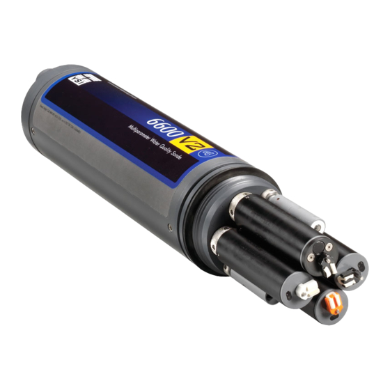
- Page 1 6-Series Multiparameter Water Quality Sondes User Manual 6-Series: 6600 V2 6600EDS V2 6920 V2 6820 V2 600 OMS V2 600XL 600XLM 600LS 600R 600QS...
- Page 2 Specific conditions where temporary sensor problems may occur are listed in this document. The Declaration of Conformity for your instrument can be found in Appendix H, EMC Performance. A similar document for YSI Model 650 is located at the end of Section 3, 650 MDS. SPECIFICATIONS For general specifications for all YSI Environmental Monitoring Systems products included in this manual, please see Appendix O, Specifications.
-
Page 3: Table Of Contents
TABLE OF CONTENTS SECTION 1 INTRODUCTION 1.1 ABOUT YSI 1.2 HOW TO USE THIS MANUAL 1.3 UNPACKING AND INSPECTION SECTION 2 SONDES 2.1 GETTING STARTED 2.2 CONNECTING YOUR SONDE 2.3 PREPARING THE SONDE FOR USE 2.4 ECOWATCH FOR WINDOWS – GETTING STARTED 2-24 2.5 SONDE SOFTWARE SETUP... - Page 4 5.14 CHLOROPHYLL 5-21 5.15 RHODAMINE 5-28 5.16 PHYCOCYANIN-CONTAINING BLUE-GREEN ALGAE 5-31 5.17 PHYCOERYTHRIN-CONTAINING BLUE-GREEN ALGAE 5-37 5.18 FLOW 5-42 SECTION 6 TROUBLESHOOTING 6.1 CALIBRATION ERRORS 6.2 SONDE COMMUNICATION PROBLEMS 6.3 SENSOR PERFORMANCE PROBLEMS SECTION 7 COMMUNICATION 7.1 OVERVIEW 7.2 HARDWARE INTERFACE 7.3 RS-232 INTERFACE 7.4 SDI-12 INTERFACE SECTION 8 UPGRADING SONDE FIRMWARE...
-
Page 5: Section 1 Introduction
The fast responses of YSI’s sensors make the systems ideal for vertical profiling, and the small size of some our sondes allows them to fit down 2-inch diameter monitoring wells. All of YSI’s multi-parameter systems... -
Page 6: Unpacking And Inspection
If any parts are damaged or missing, contact your YSI representative immediately. If you purchased the equipment directly from YSI, or if you do not know from which YSI representative your equipment was purchased, refer to Section 8, Warranty and Service Information for contact information. -
Page 7: Section 2 Sondes
SECTION 2 SONDES 2.1 GETTING STARTED The 6-Series Environmental Monitoring Systems from YSI are multi-parameter, water quality measurement, and data collection systems. They are intended for use in research, assessment, and regulatory compliance applications. Section 2 concentrates on sondes and how to operate them during different applications. -
Page 8: Connecting Your Sonde
(Figures 1-4) are a few possible configurations. Sonde to Lab Computer (recommended for initial setup) Sonde to Data Collection Platform Sonde to Portable Computer Sonde to YSI 650 MDS Display/Logger Figure 1 YSI Incorporated Environmental Monitoring Systems Operations Manual... - Page 9 Sonde to Data Collection Platform 6096 MS-8 Adapter with Flying Leads MS-8 Field Cable You will need... Sonde Field Cable 6096 Adapter with leads Sonde Data Collection Platform Figure 3 YSI Incorporated Environmental Monitoring Systems Operations Manual...
- Page 10 Sonde to 650 Display/Logger Envir onmental Monitoring Systems 650 MDS 610-DM MS-8 You will need... Field Cable Sonde Field Cable 650 MDS Display/Logger Sonde YSI 650 operates on C-cells or rechargeable batteries. YSI Incorporated Environmental Monitoring Systems Operations Manual...
-
Page 11: Preparing The Sonde For Use
To prepare the sonde for calibration and operation, you need to install probes (sensors) into the connectors on the sonde bulkhead. In addition to probe installation, you need to install a new membrane on the YSI 6562 DO Probe if you are using this item. It is recommended that you install the DO membrane before installing the probe onto the bulkhead. - Page 12 DO MEMBRANE INSTALLATION WITH THE PROBE NOT INSTALLED IN THE SONDE Remove the protective cap and the dry membrane from the YSI 6562 Dissolved Oxygen probe. Make sure that the protective cap is installed on the connector end of the probe. Do not allow the electrolyte solution to wet the probe‟s connector and O-ring seal areas.
- Page 13 Install a new O-ring by placing one side of the O-ring in the groove and rolling into place across the membrane and into the groove on the opposite side of the probe face. Avoid touching the probe face with YSI Incorporated Environmental Monitoring Systems Operations Manual...
- Page 14 2.3.2 STEP 2 - INSTALLING THE PROBES Remove the calibration cup from your sonde by hand as shown in Figure 14, to expose the bulkhead. Figure 14 TRANSPORT CUP BULKHEAD WITH PROBE PORT PLUGS YSI Incorporated Environmental Monitoring Systems Operations Manual...
- Page 15 Sondes Section 2 REMOVING THE PORT PLUGS Using the long extended end of the probe installation tool supplied in the YSI 6570 Maintenance Kit, remove the port plugs. Save all the port plugs Figure 15 for possible future use. There are a variety of probe options for the sondes. Figures 15, 16 and 17 illustrate the uses of the common tool for port plug removal.
- Page 16 6150 Optical Dissolved oxygen probe = 8 pin connector 6131 PC-Blue-green Algae probe = 8 pin connector 6132 PE-Blue-green Algae probe = 8 pin connector pH/ORP Cond./Temp. ISE‟s YSI Incorporated Environmental Monitoring Systems Operations Manual 2-10...
- Page 17 6150 Optical Dissolved oxygen probe = 8 pin connector 6131 PC-Blue-green Algae probe = 8 pin connector 6132 PE-Blue-green Algae probe = 8 pin connector pH/ORP – 4 pin YSI Incorporated Environmental Monitoring Systems Operations Manual 2-11...
- Page 18 6130 Rhodamine WT Probe, Wiping = 8 pin connector 6150 Optical Dissolved oxygen probe = 8 pin connector 6131 PC-Blue-green Algae probe = 8 pin connector 6132 PE-Blue-green Algae probe = 8 pin connector YSI Incorporated Environmental Monitoring Systems Operations Manual 2-12...
- Page 19 6850 CONDUCTIVITY DISSOLVED OXYGEN 600QS BULKHEAD Figure 23 If are working with a 600QS sonde, your instrument will arrive with the probes installed. TEMPERATURE pH GLASS/ORP pH REFERENCE 6850 CONDUCTIVITY DISSOLVED OXYGEN YSI Incorporated Environmental Monitoring Systems Operations Manual 2-13...
- Page 20 Temperature Sensor Optical Port LUBRICATE O-RINGS Apply a thin coat of O-ring lubricant, supplied in the YSI 6570 Maintenance Kit, to the O-rings on the connector side of each probe that is to be installed. Figure 25 CAUTION: Make sure that there are NO contaminants LUBRICATE O-RINGS between the O-ring and the probe.
- Page 21 Do not over-tighten. CAUTION: Be careful not to cross-thread the probe nut. The YSI 6820V2-1 and 6920V2-1 sondes can accept a single turbidity, chlorophyll, Rhodamine WT, BGA- PC, BGA-PE, or ROX DO probe. The 6600V2-2, 6600EDS V2-2, 6820V2-2, and 6920V2-2 sondes can accept and utilize two of the six optical sensors at the same time.
- Page 22 CAUTION: Be careful not to damage the Rapid Pulse DO membrane during installation of the probe guard. Figure 30 shows the YSI 6820V2-1/6820V2-2/6920V2-1/6920V2-2 probe guard; the guard for the 6600V2-2/6600V2-4 is similar. The YSI 600R, 600QS, 600XL and 600XLM probe guards resemble Figure 31. Figure 30...
- Page 23 2.3.3 STEP 3 - POWER Some type of external power supply is required to power the YSI 600R, 600QS, 600XL 6820V2-1, and the non-battery version of the 600 OMS V2-1sondes. The YSI 6920V2-1, 6920V2-2, 6600V2-2, 6600EDS V2-2, 6600V2-4, 600XLM, and battery version of the 600 OMS V2-1sondes have internal batteries or can run on external power.
- Page 24 OMS V2-1are the sondes that use alkaline batteries for power. A set of batteries is supplied with each of these sondes. If you do not have one of these sonde model types, you may skip this section. INSTALLING BATTERIES INTO THE YSI 600XLM OR 600 OMS V2-1 SONDES Figure 33 To install 4 AA-size alkaline batteries into the sonde, refer to the following directions and Figure 33.
- Page 25 Sondes Section 2 INSTALLING BATTERIES INTO THE YSI 6600V2-2, 6600EDS V2-2, AND 6600V2-4 SONDES Figure 35 IMPORTANT SAFETY FEATURE: The 116003 battery lid for the 6600V2-2, 6600EDS V2-2, and 6600V2-4 is equipped with a safety pressure-release valve. The valve will vent off any pressure build up...
- Page 26 Figures 35K and 35L CAUTION: Before installing the battery lid, ensure that the pressure release valve is closed. If the pressure release valve is open, DO NOT install (see Figures 35M and 35N). The valve YSI Incorporated Environmental Monitoring Systems Operations Manual 2-20...
- Page 27 Sondes Section 2 cannot be reset and the battery lid must be replaced before sonde deployment. Contact YSI Technical Support for instructions. Figure 35M: Closed valve Figure 35N: Open valve OK to Deploy DO NOT Deploy Lightly lubricate the o-rings on the outside of the battery cover. DO NOT lubricate the orange internal o- ring.
- Page 28 For all of the sondes, the other end of the cable is a military-style 8-pin connector (MS-8). Through use of a YSI 6095B MS-8 to DB-9 adapter, the sonde may be connected to a computer for setup, calibration, real- time measurement, and uploading files.
- Page 29 CAUTION: The 6067B cable is for laboratory use only -- it is not waterproof and should not be submersed! Sondes that are equipped with level sensors use vented cables. See Appendix G, Using Vented Level, for detailed information. YSI Incorporated Environmental Monitoring Systems Operations Manual 2-23...
-
Page 30: Ecowatch For Windows -Getting Started
9600 from the list and press Enter. From the Settings Menu, select the Font/Color and Background Color options to choose a color scheme for the EcoWatch for Windows menus. YSI Incorporated Environmental Monitoring Systems Operations Manual 2-24... -
Page 31: Sonde Software Setup
2.5 SONDE SOFTWARE SETUP There are two sets of software at work in any YSI environmental monitoring system. One is resident in your PC and is called EcoWatch for Windows. The other software is resident in the sonde itself. In this section, you will first make sure that the language associated with your sonde software is appropriate to your application and change it if necessary. - Page 32 When the update is finished (indicated on the PC screen as shown below), close the YSI Code Updater window (on the PC) by clicking on the "X" in the upper right corner of the window. Your sonde menus will now appear in the language which you selected prior to running the updater.
- Page 33 If you are unable to establish interaction with the sonde, make sure that the cable is properly connected. If you are using external power, make certain that the YSI 6651 or 6038 power supply or other 12 vdc source is properly working. Recheck the setup of the Com port and other software parameters. Also refer to Section 6, Troubleshooting.
- Page 34 At the Main menu, select System. The System Setup menu will be displayed. System Setup Menu 1-Date & time 2-Comm setup 3-Page length=25 4-Instrument ID=YSI Sonde 5-Circuit board SN:00003001 6-GLP filename=00003001 7-SDI-12 address=0 Select option (0 for previous menu): YSI Incorporated...
- Page 35 Press Esc or 0 to return to the System setup menu. Then press Esc or 0 again to return to the Main menu. ------------------Main----------------- 1-Run 5-System 2-Calibrate 6-Report 3-File 7-Sensor 4-Status 8-Advanced Select option (0 for previous menu): YSI Incorporated Environmental Monitoring Systems Operations Manual 2-29...
- Page 36 The sensor must first be enabled as described above. That parameter must be activated in the Report Setup menu described below. Select Report from the Main menu. A Report Setup menu similar to the one shown below will be displayed. YSI Incorporated Environmental Monitoring Systems Operations Manual 2-30...
- Page 37 Note also that since a 6136 turbidity probe was selected in the Sensor menu above, the units of turbidity are presented as “turbid+ NTU”. If a 6026 turbidity probe (which was offered by YSI up until 2002) had been selected, the units of turbidity would be presented as “turbid NTU”. This designation is designed to differentiate the data from the two sensor types in later analysis.
- Page 38 When this setup is verified, press Esc or 0 to return to the Advanced menu. Select 3-Sensor from the Advanced menu and make certain that the entries are identical to those shown below. YSI Incorporated Environmental Monitoring Systems Operations Manual 2-32...
- Page 39 Advanced menu, see Section 2.9.8, Advanced. Press Esc or 0 to back up to the Main menu. ------------------Main----------------- 1-Run 5-System 2-Calibrate 6-Report 3-File 7-Sensor 4-Status 8-Advanced Select option (0 for previous menu): The sonde software is now set up and ready to calibrate and run. YSI Incorporated Environmental Monitoring Systems Operations Manual 2-33...
-
Page 40: Getting Ready To Calibrate
Fill a bucket with ambient temperature water to rinse the sonde between calibration solutions or perform the calibration near a sink where the probes can be rinsed from the tap. YSI Incorporated Environmental Monitoring Systems Operations Manual 2-34... - Page 41 Please see the section below which describes the special calibration recommendations for this sensor. YSI Incorporated Environmental Monitoring Systems Operations Manual 2-35...
- Page 42 6600EDSV2-2 Sonde with Short Calibration Cup and Long Cup in Parentheses* Probe to Calibrate Upright Inverted Conductivity 275ml (520ml) 350ml (350ml) pH/ORP 175ml (400ml) 350ml (350ml) All Optical Sensors 225ml (420ml) DO NOT CALIBRATE*** YSI Incorporated Environmental Monitoring Systems Operations Manual 2-36...
- Page 43 Users may choose to purchase the shorter calibration cup sleeve for calibration of sensors other than the 6136 to reduce the volumes of calibrant. The shorter cal cup sleeve is YSI Item Number 066267 and can be obtained by contacting YSI Technical Support.
-
Page 44: Calibration Procedures
Use tables 1-8 to find the correct amount of calibrator solution. Carefully immerse the probes into the solution and rotate the calibration cup to engage several threads. YSI recommends supporting the sonde with a ring stand and clamp to prevent the sonde from falling over. - Page 45 Sal DOsat Depth Battery mm/dd/yy hh:mm:ss mS/cm mS/cm mg/L feet volts ------------------------------------------------------------------------------ To calibrate, press <Enter> when the readings are stable. 05/05/97 08:39:51 20.83 9.602 8.837 5.41 37.9 3.28 -0.252 7.06 10.2 YSI Incorporated Environmental Monitoring Systems Operations Manual 2-39...
- Page 46 CONDUCTIVITY This procedure calibrates conductivity, specific conductance, salinity, and total dissolved solids. Place the correct amount (see Tables 1-8) of 10 mS/cm conductivity standard (YSI 3163 is recommended) into a clean, dry or pre-rinsed calibration cup. Before proceeding, ensure that the sensor is as dry as possible. Ideally, rinse the conductivity sensor with a small amount of standard that can be discarded.
- Page 47 Sondes Section 2 NOTE: The YSI conductivity system is very linear over its entire 0-100 mS/cm range. Therefore, it is usually not necessary to use calibration solutions other than the 10 mS/cm reagent recommended above for all environmental applications from low conductivity freshwater to seawater. YSI does offer the 3161 (1 mS/cm) and 3165 (100 mS/cm) conductivity standards for users who want to assure maximum accuracy at the high and low ends of the sensor range.
- Page 48 Usually the Autosleep RS-232 feature in the Advanced|Setup menu will be activated for ROX calibrations, but there is no problem if it is not active. Rinse the sonde in water and dry the sonde. YSI Incorporated Environmental Monitoring Systems Operations Manual 2-42...
- Page 49 NOTE: The majority of environmental water of all types has a pH between 7 and 10. Therefore, unless you anticipate a pH of less than 7 for your application, YSI recommends a two point calibration using pH 7 and pH 10 buffers.
- Page 50 30 seconds, press Enter. After the third value calibration is complete, press Enter to return to the Calibrate menu. Thoroughly rinse and dry the calibration cups for future use. YSI Incorporated Environmental Monitoring Systems Operations Manual 2-44...
- Page 51 CALIBRATION TIP: Exposure to the high ionic content of pH buffers can cause a significant, but temporary, drift in these ISE probes (ammonium, nitrate and chloride probes). Therefore, when calibrating the pH probe, YSI recommends that you use one of the following methods to minimize errors in the subsequent readings: ...
- Page 52 To begin the calibration, place the correct amount (see Tables 1-8 above) of clear deionized or distilled water into the YSI clear calibration cup provided. Immerse the sonde in the water. Input the value 0 µg/L at the prompt, and press Enter. The screen will display real-time readings that will allow you to determine when the readings have stabilized.
- Page 53 To begin the calibration, place the correct amount (see Tables 1-8 above) of clear deionized or distilled water into the YSI clear calibration cup provided. Immerse the sonde in the water. Input the value 0 cells/mL at the prompt, and press Enter. The screen will display real-time readings that will allow you to determine when the readings have stabilized.
- Page 54 “3” key or manually rotate the sonde to remove bubbles. After the readings have stabilized, press Enter to confirm the calibration and then press Enter to return to the Calibrate menu. Thoroughly rinse and dry the calibration cups for future use. YSI Incorporated Environmental Monitoring Systems Operations Manual 2-48...
-
Page 55: Taking Readings
See Section 2.9.1 for more details. Select 3-File to enter a filename with a maximum of 8 characters. This is the file to which you will log readings. YSI Incorporated Environmental Monitoring Systems Operations Manual 2-49... - Page 56 Example: You are going to deploy the sonde for 2 weeks, collecting a set of readings every 15 minutes. You start at 6:00 PM on July 17, 1996 and end the YSI Incorporated Environmental Monitoring Systems Operations Manual 2-50...
- Page 57 Check 7-Battery to make certain that the voltage is suitable for the length of the study that you are about to begin. No change can be made to this item via the software. YSI Incorporated Environmental Monitoring Systems Operations Manual 2-51...
- Page 58 Once you press C-Start logging, a screen will appear to request confirmation. -------------Start logging------------- Are you sure? 1-Yes 2-No Select option (0 for previous menu): Select 1-Yes and the screen will change. YSI Incorporated Environmental Monitoring Systems Operations Manual 2-52...
- Page 59 If you want to terminate sooner, simply select 2-Unattended sample from the Run menu, then B-Stop logging. Select 1-yes and return to the Unattended setup menu. Stop logging? 1-Yes 2-No Select option (0 for previous menu): YSI Incorporated Environmental Monitoring Systems Operations Manual 2-53...
-
Page 60: Using Ecowatch To Upload And Analyze Data
2.8 USING ECOWATCH TO CAPTURE, UPLOAD AND ANALYZE DATA EcoWatch for Windows software is reporting and plotting software for use with the YSI 6-Series sondes. Instructions for installing this software were included in Section 2.1, Getting Started. This program can also be used to upload and view data logged to sonde memory during either discrete or unattended sampling. - Page 61 Prior to upload, a “Time window” display appears that will allow you to select portions of the logged data to upload. You may select 1-Proceed to upload all logged data from the dates and times displayed. YSI Incorporated Environmental Monitoring Systems Operations Manual...
- Page 62 You also may choose the entire file. You can use the Space Bar to stop and restart the scrolling at any time. Use the Esc key to stop the view. YSI Incorporated Environmental Monitoring Systems Operations Manual 2-56...
- Page 63 Each set of data is autoscaled to allow you to see the minimum and maximum values for each parameter during the one-week study. YSI Incorporated Environmental Monitoring Systems Operations Manual 2-57...
- Page 64 View again, both the Graph and Table items have check marks to their left, indicating that both functions are turned on. You may use your mouse to scroll up/down and left/right to view data. YSI Incorporated Environmental Monitoring Systems Operations Manual...
- Page 65 It may be somewhat awkward to scan the data table in this manner; therefore you have the option to turn off the graphical representation and allow the table to fill the window. See Figure 43. Notice now that when you click on View, the Graph item is no longer checked. YSI Incorporated Environmental Monitoring Systems Operations Manual 2-59...
- Page 66 To continue, you must close the Statistics or Study window to return to the graph or table and activate the top line menu again. As before practice viewing the functions mentioned above to gain more familiarity with these features. YSI Incorporated Environmental Monitoring Systems Operations Manual 2-60...
- Page 67 Note also that the exact time and date change to let you know specifically when an event of interest occurred. YSI Incorporated Environmental Monitoring Systems Operations Manual...
- Page 68 Setup, then Parameters. From here there are four submenus that allow you to Add/Remove parameters, change Units, change sample interval and/or x-axis (Attributes) and change the Names of the parameters you have assigned, as shown in Figure 46. YSI Incorporated Environmental Monitoring Systems Operations Manual 2-62...
- Page 69 You may be able to more clearly understand an event by zooming in/out, centering an event of interest, and setting limits to focus in on a specific area of the graph. In addition to modifying YSI Incorporated Environmental Monitoring Systems Operations Manual...
- Page 70 Refer to Figure 47 and 48 below to see the results of this particular feature. Figure 47 Selecting a Subset of Data within a Graph YSI Incorporated Environmental Monitoring Systems Operations Manual 2-64...
- Page 71 You may also create a custom report format using the File|Report command. See Figure 49 for the File menu, which shows these commands. Use the Window‟s Help function to learn more about these features. YSI Incorporated Environmental Monitoring Systems Operations Manual 2-65...
- Page 72 DO rises again during the day due to photosynthesis, CO then falls and pH increases again. The final plot after making these changes in shown in Figure 50. YSI Incorporated Environmental Monitoring Systems Operations Manual 2-66...
- Page 73 As you become more familiar with EcoWatch for Windows, the plotting, analysis and reporting functions can be accomplished easily and quickly. Practice with all of the functions and, again, do not forget to use Window‟s Help for more detail, or see Section 4, EcoWatch for Windows. YSI Incorporated Environmental Monitoring Systems Operations Manual 2-67...
-
Page 74: Sonde Menu
In the following subsections you will learn about the functions of the various menu items and when to use them. The discussion of the menu and submenu functions is organized in numerical order, beginning with Section 2.9.1 Run YSI Incorporated Environmental Monitoring Systems Operations Manual 2-68... - Page 75 Select 1-Discrete sample from the Run menu. The Discrete sample menu will be displayed. ------------Discrete sample------------ 1-Start sampling 2-Sample interval=4 3-File= 4-Site= 5-Open file Select option (0 for previous menu): YSI Incorporated Environmental Monitoring Systems Operations Manual 2-69...
- Page 76 DO readings remain constant for the number of samples necessary to fill 4 seconds. NOTE: If your have used your sonde with a 650 MDS data logger, the Sample Interval automatically be changed to 0.5 seconds. YSI Incorporated Environmental Monitoring Systems Operations Manual 2-70...
- Page 77 Quality assurance checks are performed prior to redeployment. Select 2-Unattended Sampling from the Run menu. The Unattended sample menu will be displayed. Use the following example to understand the unattended sampling option. YSI Incorporated Environmental Monitoring Systems Operations Manual 2-71...
- Page 78 Check 7-Battery to make certain that the voltage is suitable for the length of the study that you are about to begin. No change can be made to this item via the software. Note that no battery entry will appear for the 600R, 600QS, 600XL, and 6820V2-1 sondes. YSI Incorporated Environmental Monitoring Systems Operations Manual 2-72...
- Page 79 It is recommended to recover the sonde earlier than the predicted battery life, and to use new batteries for each deployment. Once you press C-Start logging, the following screen will appear. -------------Start logging------------- Are you sure? 1-Yes 2-No Select option (0 for previous menu): YSI Incorporated Environmental Monitoring Systems Operations Manual 2-73...
- Page 80 If you want to terminate sooner, simply select 2-Unattended sample from the Run menu, then B-Stop logging. Select 1-Yes and return to the Unattended setup menu. Stop logging? 1-Yes 2-No Select option (0 for previous menu): YSI Incorporated Environmental Monitoring Systems Operations Manual 2-74...
- Page 81 From the Main sonde menu select 2-Calibrate. The Calibrate menu will be displayed. Only the enabled parameters will be available for calibration. YSI Incorporated Environmental Monitoring Systems Operations Manual 2-75...
- Page 82 Appendix J of this manual. The key factor to remember, however, is that no matter which convention (DOsat % or DOsat %Local) is selected, the mg/L value will not be affected. YSI Incorporated Environmental Monitoring Systems Operations Manual 2-76...
- Page 83 Understanding the Factory Calibration of the ROX Optical DO Sensor Unlike all other sensors for YSI 6-series sondes, the response of the ROX Optical DO sensor is not linear relative to the species being measured. This non-linearity requires that the sensor be factory-calibrated at a number of oxygen values and the data fit to a third-order regression.
- Page 84 6150 probe and NOT a function of the probe, i.e., the constants reflect the characteristics of the sensor membrane and NOT the probe. When a 6150 probe is purchased from YSI, it already has a sensor membrane installed and the constants of that membrane are transferred automatically to the sonde PCB when the sensor is run for the first time.
- Page 85 ROX Optical DO calibration. Calibration Using Percent Air Saturation – 1-Point NOTE: YSI recommends that you use this method for calibration of your 6150 Dissolved Oxygen Sensor to obtain the maximum accuracy under normal operating conditions. Place the sensor either (a) into a calibration cup containing about 1/8 inch of water which is vented by loosening the threads or (b) into a container of water which is being continuously sparged with an aquarium pump and air stone.
- Page 86 CAUTION: Be certain that you wait at least 10-12 minutes and until the readings are stable for at least 2 minutes before confirming the zero point calibration entry. YSI Incorporated Environmental Monitoring Systems Operations Manual 2-80...
- Page 87 MUST carefully remove all traces of the reagent from the probes prior to proceeding to the second point. YSI recommends that the second calibration point be in air-saturated water if you use sodium sulfite solution as your zero oxygen medium.
- Page 88 For example, the pH of YSI “pH 7 Buffer” is 7.00 at 25 C, but 7.02 at 20 C. After inputting the proper pH value for your calibration temperature, press Enter again, and the screen will display real-time readings that will allow you to determine when the pH and temperature readings have stabilized.
- Page 89 For best results, insure a temperature difference of at least 10 C between the two 1 mg/L standards. NOTE: YSI strongly recommends the use of the 3-point protocol to ensure the best possible performance from all ISE sensors (ammonium, nitrate, and chloride)
- Page 90 This effect is likely due to the larger optical cell volume of the 6136. Thus, for example, the label of the YSI 6073 turbidity standard bottle indicates that the value of the standard is 100 NTU when used for calibration of the 6026 sensor, but 126 NTU when used to calibrate the 6136.
- Page 91 Place the sonde in clear water, and input 0 at the screen prompt. Press Enter and the screen will display real-time readings that will allow you to determine when the fluorescence readings have stabilized. Press YSI Incorporated Environmental Monitoring Systems Operations Manual...
- Page 92 See Section 5.14, Principles of Operation and Appendix I. Chlorophyll Measurements for more information on the proper calibration of your chlorophyll sensor. OPTIC BGA-PC YSI Incorporated Environmental Monitoring Systems Operations Manual 2-86...
- Page 93 (a) phytoplankton suspensions of known BGA-PE content, and (b) dye solutions whose fluorescence can be correlated to that of BGA-PE. The user is responsible for YSI Incorporated Environmental Monitoring Systems Operations Manual 2-87...
- Page 94 Select the 3-point option for maximum accuracy over the entire range of 0 to 200 ug/L. As for the 2-point procedure, one of the standards must be 0 NTU. The procedure for this calibration is the same as for a 2- YSI Incorporated Environmental Monitoring Systems Operations Manual...
- Page 95 NOTE: When using the 650 MDS as the sonde interface device, the “uncal” operation is performed by holding the Enter key down and then pressing the Esc key. See Section 3 of this manual for more details. YSI Incorporated Environmental Monitoring Systems Operations Manual...
- Page 96 3-Samples: 4-Bytes: ------------------File----------------- 1-Directory 4-View file 2-Upload 5-Quick view file 3-Quick Upload 6-Delete all files Select option (0 for previous menu): 1 Filename Samples 1-BRIDGE1.dat 2-BRIDGE2.dat 3-UPLAKE.dat 4-CLRLAKE2.dat 5-DWNLAKE2.dat 6 - 00003001. YSI Incorporated Environmental Monitoring Systems Operations Manual 2-90...
- Page 97 Note that the default value of the conductivity “Value” is 1.00 in the .glp format shown above. This relative number is equivalent to a real cell constant of 5.00 which is provided in the Advanced|Cal YSI Incorporated Environmental Monitoring Systems Operations Manual...
- Page 98 Select 2-Upload to view file lists in memory (same as shown above) and then upload the data to a PC or to the YSI 650 MDS Display/Logger. The uploaded data can then be processed with YSI EcoWatch for Windows to allow data manipulation and to easily generate reports, plots, and statistics.
- Page 99 PC6000 format will transfer the data so that it will be compatible with the EcoWatch for Windows (supplied with your sonde) software package. YSI recommends data transfer in this format since it is significantly more rapid than other transfer options. If this data is required in Comma & Quote Delimited and/or ASCII formats, the user can quickly generate data in these formats using the Export function in EcoWatch for Windows.
- Page 100 PC, a .glp file will indeed be transferred, but it will not be possible to open it using the current YSI software or any other text editor. Thus, during a direct transfer of the .glp file to your PC, either the CDF or ASCII formats should be used.
- Page 101 1-Version identifies the specific version of sonde software loaded in the sonde. This number is especially useful if you are calling YSI Technical Support. It may also be useful to you if you are comparing 2 or more sondes purchased at different times.
- Page 102 GLP file designation. 1-Date & time 2-Comm setup 3-Page length=25 4-Instrument ID=YSI Sonde 5-Circuit board SN:00003001 6-GLP filename=00003001 7-SDI-12 address=0 Select option (0 for previous menu): Select Date &...
- Page 103 The parameters listed depend on both the sensors available and enabled on your sonde. Therefore your screen may not be identical to that shown below. Select Report from the Main sonde menu to setup the report section. The Report Setup menu will be displayed. YSI Incorporated Environmental Monitoring Systems Operations Manual 2-97...
- Page 104 ODOsat %Local”. The parameters “PAR1” and “PAR2” are associated with a special sonde equipped with a sensor for Photosynthetically Active Radiation (PAR) which can be purchased from the YSI Massachusetts. See Section 9 of this manual for contact information and Appendix K for a brief description of the PAR system for potential users.
- Page 105 BGA-PC RFU Relative fluorescence units for the BGA-PC sensor BGA-PE cells/mL Phycoerythrin-Containing Blue-green Algae content in cells/mL BGA-PE RFU Relative fluorescence units for the BGA-PE sensor Rhod ug/L Rhodamine WT in micrograms/liter YSI Incorporated Environmental Monitoring Systems Operations Manual 2-99...
- Page 106 The following screen is the submenu selection structure for ISE3, ISE4 and ISE5. --------------Select type-------------- 1-( )ISE3 NH4+ 2-( )ISE3 NO3- 3-( )ISE3 Cl- 4-( )ISE3 PAR1 Select option (0 for previous menu): YSI Incorporated Environmental Monitoring Systems Operations Manual 2-100...
- Page 107 Select option (0 for previous menu): Any available optical probe can be installed in any optical port on YSI 6-series sondes. If a single port is present (600 OMS V2-1, 6820V2-1, 6920V2-1), then the port will be designated “Optic T” in the software even though the port is not physically labeled with a “T”...
- Page 108 0.6 to 1.5 Range is ratio of (M2-M1) to (A2-A1) Turb M2 1000 Turb+ Offset -10 to 20 Turb+ A1 0.6 to 1.5 Range is ratio of M1 to A1 Turb+ M1 YSI Incorporated Environmental Monitoring Systems Operations Manual 2-102...
- Page 109 2- Start up. This option allows the user to select the mode of sonde operation when power is applied or a “reset” command is issued. After pressing the “2” key, the following options will be displayed. YSI Incorporated Environmental Monitoring Systems Operations Manual...
- Page 110 SDI-12 mode. This is basically the same as item 5 above except that it is used in communication via the SDI-12 interface. Also, the sonde will “sleep” in about 100 milliseconds in the absence of communication, rather that waiting one minute in the Auto sleep RS-232 mode. YSI Incorporated Environmental Monitoring Systems Operations Manual 2-104...
- Page 111 8-( ) Sample and Hold. This feature is designed to be activated ONLY for studies in which your sonde is attached to a YSI 6500 Process Monitor. When “Sample and Hold” is active, the 6500 display and the SCADA output of the 6500 becomes equivalent to the internal memory of the sonde while an Unattended study is running.
- Page 112 The units are feet. You may enter positive or negative values (range is -276 to 29028) to represent altitudes above or below sea level. This value is used in the YSI Incorporated Environmental Monitoring Systems Operations Manual 2-106...
- Page 113 However, there may be certain situations in which greater DO accuracy can be attained by increasing this time. Consult YSI Technical Support if you feel that your DO warm up time is incorrect. This item will only appear if the Rapid Pulse Polarographic DO sensor is enabled in the Sensors menu.
- Page 114 6026 and 6136 sensors. The default values of 0.3 (6026) and 0.6 (6136) should not be changed by the user without consulting YSI Technical Support. This item will only appear if a turbidity sensor is enabled in the Sensor menu.
- Page 115 Rhodamine WT would appear in the display below if it had been activated as a sensor. All “other” sensors use the same time constant as shown below. YSI Incorporated Environmental Monitoring Systems Operations Manual 2-109...
- Page 116 The temperature and oxygen readings taken in the water will be very similar to those taken in the air. The conductivity YSI Incorporated Environmental Monitoring Systems Operations Manual...
-
Page 117: Care, Maintenance And Storage
2.10.1 SONDE CARE AND MAINTENANCE The YSI 6570 Maintenance Kit is available for use with your sonde. The kit includes several items that will be helpful or necessary to perform the proper routine maintenance on your sonde. The 6570 Maintenance Kit includes two types of O-rings (for probes and cable connector), probe/installation/replacement tools, two cleaning brushes for the conductivity sensor, O-ring lubricant, and a syringe for cleaning the depth sensor port. - Page 118 However, if there is any indication at all of damage, the o-ring should be replaced with an identical item from the YSI 6570 Maintenance Kit supplied with your sonde. At the time of o-ring replacement, the entire o-ring assembly should be cleaned as described below.
- Page 119 If any moisture is present, use compressed air to completely dry the connector. If the connector is corroded, return the sonde to your dealer or directly to YSI Technical Support, see Section 9, Warranty and Service Information, for details. When you reinstall a probe or port plug, lightly grease the O-ring with lubricant supplied in the YSI 6570 Maintenance Kit.
- Page 120 CAUTION: MAKE CERTAIN THAT THE WATER IN THE VESSEL DOES NOT COMPLETELY EVAPORATE DURING THE REHYDRATION STEP. YSI Incorporated Environmental Monitoring Systems Operations Manual 2-114...
- Page 121 Sondes Section 2 YSI recommends the optical DO membrane assembly be replaced once a year in order to assure the maximum accuracy for the sensor and the 6155 kit allows the user to carry out this replacement without returning the sensor to the factory. The following section provides detailed instructions for replacement of the optical DO membrane assembly on the YSI Optical DO sensor.
- Page 122 Sondes Section 2 Membrane Installation Instructions Use the schematic below as an aid in replacement of the YSI Optical DO membrane. Wiper Assembly Sensing Membrane Membrane Assembly Note: The following steps can be carried out with the probe either installed in the sonde or removed from it.
- Page 123 Soak the probe for 30-60 minutes in one molar (1 M) hydrochloric acid (HCl). This reagent can be purchased from most distributors. Be sure to follow the safety instructions included with the acid. YSI Incorporated Environmental Monitoring Systems Operations Manual...
- Page 124 Heat for about one hour at about 200° C (about 400° F). The desiccant should then be cooled in a suitable, tight container before refilling the unit. The color of the desiccant will return to blue if the YSI Incorporated Environmental Monitoring Systems Operations Manual...
- Page 125 WIPER reinstallation. Follow the instructions supplied with the probe to ASSEMBLY ensure proper installation of the new wiper assembly. NON-WIPING TURBIDITY PROBE Additional wipers are available from YSI. YSI Incorporated Environmental Monitoring Systems Operations Manual 2-119...
- Page 126 GENERAL RECOMMENDATIONS FOR SHORT TERM STORAGE The recommended short term or interim storage procedure is simple and identical for all sondes -- YSI 600R, 600QS, 600XL, 600XLM, 6820V2-1, 6820V2-2, 6920V2-1, 6920V2-2, 6600V2-2, 6600EDS V2-2, 6600V2-4, and 600 OMS V2-1.
- Page 127 LONG-TERM STORAGE OF PROBES The following sections provide additional details on the storage of individual sensors associated with instruments in the 6-Series product line from YSI. TEMPERATURE No special precautions are required. Sensors can be stored dry or wet, as long as solutions in contact with the thermistor probe are not corrosive (for example, chlorine bleach).
- Page 128 Do not use deionized or distilled water in this case, as it may damage the pH glass sensor, which must remain in the sonde. At the end of the storage time, remove the existing membrane and re-membrane the probe using new electrolyte. YSI Incorporated Environmental Monitoring Systems Operations Manual 2-122...
- Page 129 Long Term Storage: ORP is not available on the YSI 600R. For the 600QS, where the ORP sensor cannot be removed from the sonde, store the sensor in tap water in a sealed storage bottle. For all other YSI 6- series sondes, the recommended long term storage protocol is identical.
- Page 130 TURBIDITY, CHLORPHYLL, BGA-PC, BGA-PE, AND RHODAMINE WT No special precautions are necessary for either the short or long-term storage of these YSI optical probes. However, for long-term storage, the user may wish to remove the probe from the sonde, replace it with a port plug, and store the probe in dry in air to minimize any cosmetic degradation of the probe body and to maximize the life of the wiper.
-
Page 131: Introduction
Upload data from sondes for transfer to PC. GETTING STARTED This section is designed to quickly familiarize you with the hardware and software components of the YSI 650 and its accessories. By the end of Section 3.2 you will have... ... - Page 132 If any parts are damaged or missing, contact your YSI representative immediately. If you do not know which YSI dealer you obtained your YSI 650 from, refer to Section 8 of your 6-series sonde manual for contact information.
- Page 133 650, and the management of these data files are described in detail in Sections 3.5, 3.6, and 3.7 of this manual. 3.2.3 650 CONFIGURATIONS There are a number of ways that you can configure the YSI 650. Below is a list of possible configurations and corresponding diagrams. ...
- Page 134 Figure 3. 650 interfaced to PC for data transfer or software upgrade. You will need: YSI 655174 655174 PC Interface PC interface Cable cable PC with active serial port PC Serial port (DB-9) YSI Environmental Monitoring Systems Operations Manual...
- Page 135 The setup of these configurations is described in detail in subsequent sections of this manual. They are presented here so that your will be able to ascertain if you have all of the parts necessary for your applications. YSI Environmental Monitoring Systems Operations Manual...
- Page 136 Strain Relief Lanyard Note that the YSI 650 keypad consists of 20 keys as shown in the diagram above. There are four function keys, up, down, right and left arrow keys and an alpha/numeric keypad. The top left key that has a green circle and line, , is the ON/OFF key.
- Page 137 3.2.5 BATTERIES AND CHARGING The YSI 650 can be powered either with 4 alkaline C cells or a rechargeable NiMH battery pack. With the C-cell configuration, the user will be able to power a typical YSI 6-series sonde (active dissolved oxygen and one optical sensor) for approximately 45 hours of continuous operation.
- Page 138 Reinstall battery lid and tighten the 4 captive screws securely and evenly using a Phillips or slotted screwdriver. Do not overtighten. 3.2.5.2 BATTERY INSTALLATION – RECHARGEABLE BATTERY PACK The YSI 6113 rechargeable battery pack is self-contained and is easily installed according to the instructions and diagrams below: ...
- Page 139 Note that YSI provides recharge options for many countries in the selection or the 6116, 6126, and 6127 kits. However, it is possible that the power cord options in these kits will not be correct for some users. In these cases, users should purchase the 6126 or 6127 kit and substitute their local PC type power cord for the power cord shipped with the kit.
- Page 140 3.2.6 TURNING THE INSTRUMENT ON Turn the instrument on by pressing and releasing the on/off button on the top left of the instrument keypad. The following screen should be displayed. Main Display Status Bar YSI Environmental Monitoring Systems Operations Manual 3-10...
- Page 141 (lightens) the contrast. NOTE: The backlight itself will only be activated if the backlight key is pressed and released. You must hold down the backlight key to adjust the contrast. YSI Environmental Monitoring Systems Operations Manual 3-11...
- Page 142 650 MDS Section 3 3.2.8 USING THE YSI 650 KEYPAD On/Off Backlight Arrows Escape Key Enter Key Alpha/Numeric Keys Minus/Hyphen (-) Key Period (.) Key The 650 keypad allows the user to navigate various sonde and 650 menu selections and to make alpha/numeric entries into both the 650 and sonde software.
- Page 143 Use the arrow keys to highlight the System setup selection and press the Enter key. A display similar to the following will appear (Note that the exact format of your displays will depend on the software version): YSI Environmental Monitoring Systems Operations Manual 3-13...
- Page 144 For example, 2:00 PM must be entered as 14:00. Finally, press the Escape key to return to the System setup menu. Now highlight the Instrument ID selection and press Enter. The following display will appear. YSI Environmental Monitoring Systems Operations Manual 3-14...
- Page 145 The connection between the sonde and the 650 is made via the mating of MS-8 connectors on the standard YSI field cable and the bottom of the 650 case. To make the connection, hold the 650 in one hand, place the 650 and cable connectors together, and rotate the field cable connector until engagement occurs.
- Page 146 These problems can usually be overcome by either simply pressing the on/off key to reactivate the meter display or by resetting the instrument by removal of battery power as described in YSI Environmental Monitoring Systems Operations Manual 3-16...
- Page 147 2.10.2 GPS Reading. This value will be present only if a user-supplied GPS unit with NMEA 0183 format is connected to the 650 by the optional YSI 6115 cable. The setup of a GPS interface is described in more detail in Section 3.8 below. Once properly connected to a GPS instrument, the values displayed in the Status Bar are updated in real-time as the system is moved from location to location.
-
Page 148: Setting Up The
To utilize the full capability of the 650 MDS, you will need to upgrade your version of EcoWatch for Windows from the YSI World Wide Web page (www.ysi.com). Access the YSI Environmental Web Page, select “tech support” from the header, and then “Downloads”. After registration, select the EcoWatch for Windows upgrade entry and follow the instructions provided. -
Page 149: Software Version
The software version of your 650 is shown in the first line of the System setup menu. As enhancements are introduced to the 650, you will be able to upgrade your 650 from the YSI web page. This item will be used to track those upgrades and will be useful to YSI Technical Support personnel if you have questions about the function of the instrument. - Page 150 .glp extension (e.g., 00003245.glp) will automatically be generated and stored in 650 memory. Each additional barometer calibration record for will also be stored. See Section 6.3 below for the transfer of this file to a computer for viewing and storage. YSI Environmental Monitoring Systems Operations Manual 3-20...
-
Page 151: Sonde Menu Interface
6-series sonde is attached to a PC as shown below. ------------------Main-------------- 1-Run 5-System 2-Calibrate 6-Report 3-File 7-Sensor 4-Status 8-Advanced Select option (0 for previous menu): YSI Environmental Monitoring Systems Operations Manual 3-21... - Page 152 Uploading files from the sonde memory to the 650. Earlier YSI display/loggers, such as the 610 D and 610 DM, had many of these functions as distinct items in the display menu structure – a significant difference from the 650.
- Page 153 Section 3 3.4.2 SONDE MENU EXAMPLES To become familiar with the 650 Sonde menu function, YSI recommends that the user connect a sonde to their 650 and proceed through the following two examples of common sonde interface operations. Example 1: Setting up the Report Output – Activation of the Salinity Parameter Highlight the Sonde menu selection in the 650 Main menu and press Enter.
- Page 154 When the dissolved oxygen reading is stable, press the Enter key to confirm the calibration as indicated by the message “Calibrated” in the header. In addition, the message in the upper window will change from YSI Environmental Monitoring Systems Operations Manual 3-24...
- Page 155 650 memory with the 650 display indicating that an upload is in progress. The uploading of data files from sondes to the 650 is demonstrated in greater detail in Section 3.7 below. YSI Environmental Monitoring Systems Operations Manual 3-25...
- Page 156 As explained in Section 2 of the 6-series manual, the setup of the Autosleep RS-232 function of the sonde should be governed by the following rules: Unattended sample studies/Remote deployments – Autosleep Active Discrete sample studies with user present – Autosleep Inactive YSI Environmental Monitoring Systems Operations Manual 3-26...
-
Page 157: Logging Data With The
650 memory with the sample interval set in the Logging setup menu of the 650. NOTE: Logging to sonde memory may not be possible for some older version 600R, 600XL, and 6820 sondes that were purchased prior to September 1999. YSI Environmental Monitoring Systems Operations Manual 3-27... - Page 158 While the following sections will show that the logging functions of the 650 have a high degree of flexibility and capability, from a basic point of view, logging with the 650 is simple: YSI Environmental Monitoring Systems Operations Manual 3-28...
- Page 159 3.5.2 LOGGING DATA TO SONDE MEMORY 3.5.2.1 INTRODUCTION All YSI 6-series sondes sold since September 1999 have memory present on their internal PCBs. In addition, all 600XLM, 6920, and 6600 sondes have internal memory, regardless of the date of purchase. Interface of these sondes to a 650 allows the user to easily store data (either a single point or a continuous stream) to the sonde memory.
- Page 160 Discrete sample menu of the sonde, and thus the user MUST activate the 650 Run display indirectly using the 650 Sonde menu selection as detailed above. YSI Environmental Monitoring Systems Operations Manual 3-30...
- Page 161 Enter to begin logging data to sonde memory. The message in the sonde logging window changes to Stop logging, indicating that logging has successfully been activated. YSI Environmental Monitoring Systems Operations Manual 3-31...
- Page 162 With sondes of this type, you will not be able to log data to the sonde – only to the 650 as detailed in the following section. With these no-memory sondes attached to your 650, the Run display will show a blank Sonde logging window as shown below. YSI Environmental Monitoring Systems Operations Manual 3-32...
- Page 163 The factory default sample interval of 1 second will therefore need to be changed to 10 seconds. To set the sample interval, highlight the Logging setup entry in the 650 Main menu and press Enter. YSI Environmental Monitoring Systems Operations Manual 3-33...
- Page 164 The user places the sonde in the water and then highlights the Start logging selection in the 650 logging window (upper left) and presses Enter. The user is then prompted to enter a Filename and Site description for the study as shown below. YSI Environmental Monitoring Systems Operations Manual 3-34...
- Page 165 “mismatched” with “DO %” from the old setup. The screen thus shows that salinity has been added to the parameter list between the two logging studies and must be removed if the original file is to be appended with further data. YSI Environmental Monitoring Systems Operations Manual 3-35...
- Page 166 For Multi-site Designations, there will a single File Name with multiple Site Names and Site Numbers. The following displays show examples of Single and Multi-Site Designations. Site List Single-Site Designations with Different File Names YSI Environmental Monitoring Systems Operations Manual 3-36...
- Page 167 Site list is active to display the full capability of the Logging setup as shown below. To set up a list with Single-Site Designations the selection Store Site number should be INACTIVE (as shown below) before proceeding. YSI Environmental Monitoring Systems Operations Manual 3-37...
- Page 168 650 logging setup. Then travel to the first location, identified by the Filename WEST, activate the 650 Run display, and then select either a continuous data stream (Start logging) or a single data entry (Log single point) from the 650 logging window. YSI Environmental Monitoring Systems Operations Manual 3-38...
- Page 169 Details of the files (shown by pressing Enter when the File is highlighted in Directory) are shown below. Note that the site name (BLUE LAKE) is listed in the file since the data was logged using Single-Site Designations. YSI Environmental Monitoring Systems Operations Manual 3-39...
- Page 170 The real key, however, in configuring the Logging setup display for use with a Multi-site list is that you MUST make certain that the selection Store Site number is ACTIVE (as shown below) before proceeding. YSI Environmental Monitoring Systems Operations Manual 3-40...
- Page 171 WEST Site name (since your are at that location) and press Enter to log data to the 650 memory. An indication that the logging was successful will appear in the 650 logging window. YSI Environmental Monitoring Systems Operations Manual 3-41...
- Page 172 Note that there is NO Site name listed for the file BLUELAKE since data from more than on site was logged to it. Now highlight the View file selection and press Enter to display the data in BLUELAKE as shown below. YSI Environmental Monitoring Systems Operations Manual 3-42...
- Page 173 (add) a file above the present cursor position, simply highlight the proper entry and press the Right arrow key while holding down the Enter key as shown in the following example. Note that two sites were inserted in the initial site list using this method. YSI Environmental Monitoring Systems Operations Manual 3-43...
- Page 174 Remember that, when editing your Site list, you will have no effect on the actual files which were previously logged to 650 memory nor on the data in the files. See Section 3.6 below. YSI Environmental Monitoring Systems Operations Manual 3-44...
- Page 175 3.5.4 650 LOGGING – “CANS” AND “CAN’TS” The use of the 650 to facilitate the storage of data from YSI 6-series sondes has been described in some detail in the sections above. Unfortunately, the high levels of capability and flexibility of the 650 logging function might also be viewed as complexity which, in turn, can confuse some users about how to employ the 650 in their particular application.
-
Page 176: Managing 650 Files
650 MDS Section 3 3.5.4.2 SUMMARY OF 650 LOGGING LIMITATIONS WITH A 650/YSI SONDE SYSTEM, THE USER CANNOT: Log GPS and/or barometer data to sonde memory. Log GPS and/or barometer to 650 memory without a sonde attached and the 650 in Run mode. See ... - Page 177 (PROFILE1) and press Enter to generate a display of the details of this file. Press Escape and then highlight the second file (DEPLOY1) and press Enter to again display information about the file. YSI Environmental Monitoring Systems Operations Manual 3-47...
- Page 178 (Discrete) or to the memory of a sonde set up in an Unattended sampling study. Only for Unattended sampling studies will the actual sample interval be displayed. When the Interval has the designation “Discrete”, the time between samples can be determined by viewing the data as described below. YSI Environmental Monitoring Systems Operations Manual 3-48...
- Page 179 This frequently used command is used to transfer data files resident in the 650 memory (either logged directly or uploaded from sonde memory) to a PC that is running YSI EcoWatch for Windows software. Once transferred, the data can be custom configured, plotted, and reported in tabular form using this software package.
- Page 180 Note that there are three file types (with different extensions) in the above directory: (1) Files with .dat extensions which are data files logged to either sonde memory of 650 memory and which are in YSI PC6000 format; (2) Files with a .txt extension which are data files logged to sonde memory and then transferred to 650 memory in either ASCII or CDF format;...
- Page 181 PC before carrying out the procedure. Note, however, that use of the Delete all files command will have no effect on any Site Designations which have been entered from the Edit site list selection. YSI Environmental Monitoring Systems Operations Manual 3-51...
-
Page 182: Uploading Data From Sondes
3.7.2 UPLOAD PROCEDURE After attachment of the sonde to the 650 with a YSI field cable, turn on the 650, highlight the Sonde menu selection and press Enter to display the Main sonde menu. Highlight the File selection and press Enter. -
Page 183: Using Gps With
Purchase from your GPS manufacturer a cable that connects at one end to the GPS unit and has at its other end a female DB-9 connector for interface with the YSI 6115 GPS cable. Once these requirements are met, proceed according to the following instructions, consulting Figure 2 in Section 3.2.3 above for assistance:... - Page 184 These criteria mean that the GPS coordinates of Yellow Springs, Ohio, USA are approximately 39 47.33’ latitude and -83 54.13’ longitude as read in EcoWatch, but N 39 47.33’ W 83 54.13’ as displayed by the 650. YSI Environmental Monitoring Systems Operations Manual 3-54...
-
Page 185: Using The 650 Barometer
650 to water (either spraying or submersion). Then contact YSI Technical Support as soon as possible for advice. The 650 barometer reads true barometric pressure and therefore is unlikely to agree with values from your local weather service which are usually corrected to sea level before being distributed. - Page 186 EcoWatch, with the user having the ability to change units from the EcoWatch menus. For example, data stored in 650 memory in units of mm Hg units can easily be converted to readings in mBar after upload. YSI Environmental Monitoring Systems Operations Manual 3-56...
-
Page 187: Upgrading 650 Software
Web page, the instrument should be prepared for upgrade by attaching the MS-8 end of the YSI 655174 PC Interface cable to the 650 and the DB-9 end of the 655174 to a serial port of a PC which... -
Page 188: Troubleshooting
6117 battery pack. If these guidelines and tips fail to correct your problem or if any other symptoms occur, contact YSI Technical Support for advice. See Section 8 of the 6-series manual for contact information. -
Page 189: Ferrite Bead Installation
See the drawing below for assistance. Snap the two pieces of the bead together making certain that the tabs lock securely. When the installation is complete, the 655174 and 6116 cables should resemble the following schematic drawings. YSI Environmental Monitoring Systems Operations Manual 3-59... -
Page 190: Safety Considerations
If the battery pack is removed from the 650, do not store it in pockets or packaging where metallic objects such as keys can short between the positive and negative terminals. Precautions for Users with Small Children Keep the battery pack out of reach of babies and small children. YSI Environmental Monitoring Systems Operations Manual 3-60... - Page 191 Store the battery pack between the temperatures of –20 and 30 C. Before using the battery pack, be sure to read the operation manual and all precautions carefully. Then store this information carefully to use as a reference when the need arises. YSI Environmental Monitoring Systems Operations Manual 3-61...
- Page 192 YSI Technical Support. 10. Do not disassemble charger other than to change the fuse as instructed. Replace the part or send it to YSI Product Service if repair is required. Incorrect reassembly may result in a risk of electric shock or fire.
-
Page 193: Mds Specifications
Section 3 CAUTION: If water has contacted the rechargeable battery pack, do not attempt to reuse it until it has been evaluated by YSI Product Service. Failure to follow this precaution can result in serious injury to the user. If it is suspected that leakage into the main cavity of the case has occurred, remove the batteries immediately and return the instrument to YSI Product Service for damage assessment. - Page 194 Standard Backlight Feature: 4 LEDs illuminating LCD Keyboard: 20 keys including Meter On/Off, Backlight On/Off, Enter, Escape, 10 Number/Letter Entry Keys, 2 Vertical arrow keys, 2 Horizontal arrow keys, 1 minus/hyphen entry key, 1 decimal point/period YSI Environmental Monitoring Systems Operations Manual 3-64...
- Page 195 650 MDS Section 3 YSI Environmental Monitoring Systems Operations Manual 3-65...
- Page 196 650 MDS Section 3 YSI Environmental Monitoring Systems Operations Manual 3-66...
-
Page 197: Section 4 Ecowatch For Windows
SECTION 4 ECOWATCH FOR WINDOWS INTRODUCTION EcoWatch for Windows is intended to be the PC software interface to YSI’s 6-Series environmental monitoring systems equipment. From EcoWatch you can program field equipment, upload data collected on the equipment, and format the data in easy to understand graphs and tables. - Page 198 Windows or PC6000 software. 9 – Study A single data file in PC6000 format. 4.1.3 TUTORIAL This brief EcoWatch tutorial is to be used with the sample data file that is provided with EcoWatch. YSI Incorporated Environmental Monitoring Systems Manual...
- Page 199 File Open. To display or hide the toolbar, open the View menu and click on the Toolbar command. A check mark appears next to the menu item when the toolbar is displayed. The toolbar is displayed across the top of the application window, below the menu bar. YSI Incorporated Environmental Monitoring Systems Manual...
- Page 200 Enlarge a selective portion of graph. Center the graph under the cursor. Enlarge graph or table 20%. Reduce graph or table 20%. Return graph or table to its normal state (unzoom) Redraw the graph. YSI Incorporated Environmental Monitoring Systems Manual...
- Page 201 TYPICAL APPLICATION Suppose you want to measure Dissolved Oxygen, pH, Temperature, and Turbidity in a nearby stream and decide to start with a 30-day deployment using the YSI 6920 sonde. The task can be organized into several steps: 1. Calibrate and setup the sonde.
- Page 202 EcoWatch for Windows Section 4 5. Print Your Graph To print the graph, open the File menu, choose Print Setup or Print to choose exactly how the print should look. YSI Incorporated Environmental Monitoring Systems Manual...
-
Page 203: Data Acquisition And Analysis
Section 4 4.2 DATA ACQUISTION AND ANALYSIS 4.2.1 CONNECT A YSI SONDE OR A 650 DISPLAY/LOGGER EcoWatch may be used with various sondes or display/loggers. To utilize the configuration that will work best for your application, make sure that you have all of the components that are necessary. - Page 204 Data that is processed in EcoWatch typically originates in a sonde with batteries and is uploaded to a PC. To upload data from a YSI sonde, connect the sonde to your PC and open the EcoWatch software. Use the Sonde button on the toolbar to communicate with the sonde software.
- Page 205 Note that there are three file types (with different extensions) in the above directory: (1) Files with .dat extensions which are data files logged to either sonde memory of 650 memory and which are in YSI PC6000 format; (2) Files with a .txt extension which are data files logged to sonde memory and then transferred to 650 memory in either ASCII or CDF format;...
- Page 206 Click this button to magnify by 20%. This command can be used on both graphs and data tables. Zoom Out Click this button to reduce magnification by 20%. This command can be used on both graphs and data tables. YSI Incorporated Environmental Monitoring Systems Manual 4-10...
- Page 207 The Settings command in the Real-time menu takes you to a dialog where you can set the x-axis time and the sample interval. YSI Incorporated Environmental Monitoring Systems Manual 4-11...
-
Page 208: Ecowatch Menu
Choose this button to connect to a network location, assigning it a new drive letter. This button is hidden if your computer is not connected to a network. The screen above has the network button hidden. YSI Incorporated Environmental Monitoring Systems Manual 4-12... - Page 209 (.DAT), have the same number of parameters, and the same parameter types (the parameter setup must be identical). Data record time-stamps in the destination data file will be stored in ascending order. YSI Incorporated Environmental Monitoring Systems Manual 4-13...
- Page 210 If a graph or table is active, then choosing this command will send its contents to the Windows clipboard so that it can be pasted into other programs. This is a normal method of transfer data between different Windows programs. Shortcuts Toolbar: Keys: CTRL+C YSI Incorporated Environmental Monitoring Systems Manual 4-14...
- Page 211 Saved displays are associated with the data file. You can have as many as nine saved displays for each data file. When loading a display you will be asked to choose from among the names of saved displays. YSI Incorporated Environmental Monitoring Systems Manual 4-15...
- Page 212 .WMF file and then import it into another Windows program. CDF stands for Comma Delimited, sometimes referred to as a Comma and Quote Delimited File. This format is commonly used by spreadsheet and database programs. In this type of file, commas separate YSI Incorporated Environmental Monitoring Systems Manual 4-16...
- Page 213 Wordpad to open reports that are larger than 64K. Unless you change it, the report file will have the same location as your data file (.DAT) and has the same name with a .RPT file extension. YSI Incorporated Environmental Monitoring Systems Manual 4-17...
- Page 214 This command allows the user to preview how the document will appear when it is printed. This command only works for data that is displayed in a table format, not when the data is in graph format. YSI Incorporated Environmental Monitoring Systems Manual...
- Page 215 Select the printer you want to use. Choose the Default Printer; or choose the Specific Printer option and select one of the current installed printers shown in the box. You install printers and configure ports using the Windows Control Panel. YSI Incorporated Environmental Monitoring Systems Manual 4-19...
- Page 216 Page headers and footers can be customized with respect to font and placement. Both the header and footer have separate tabs as shown below. Once the desired profile is created, it can be saved for use every time the particular data file is opened. YSI Incorporated Environmental Monitoring Systems Manual 4-20...
- Page 217 This command does not function in this version of EcoWatch. REMOVE PARAMETERS When entire column(s) of data is selected, including the heading(s), this command will remove the parameter(s) from both the data table and graph. YSI Incorporated Environmental Monitoring Systems Manual 4-21...
- Page 218 A check mark appears next to the menu item when the Status Bar is displayed. The right areas of the status bar indicate which of the following keys are latched down: The Caps Lock key is latched down. YSI Incorporated Environmental Monitoring Systems Manual 4-22...
- Page 219 If you click on any minimum or maximum value, then a small box will appear showing the date and time when the minimum or maximum point occurred. YSI Incorporated Environmental Monitoring Systems Manual 4-23...
- Page 220 This command will display a dialog box describing the study. It will show the sonde type and serial number that was used to collect the data, the parameters available, the logging interval, and the beginning and ending times of the sample. Shortcuts Toolbar: YSI Incorporated Environmental Monitoring Systems Manual 4-24...
- Page 221 Several communication menu options are only available when a terminal window is opened. SETTINGS The Communications Settings dialog box is where you can configure the communications ports. The settings are organized into the following three tabs. YSI Incorporated Environmental Monitoring Systems Manual 4-25...
- Page 222 You may choose Xon/Xoff, or RTS/CTS, or Both or None. Xon/Xoff is often referred to as software handshaking and RTS/CTS as hardware handshaking. If you are using a YSI sonde select Xon/Xoff. Modems usually require RTS/CTS. Modem Setup This is where you enter the settings for your modem.
- Page 223 Copy to Custom. Choose Custom from the list and edit the settings. It transfers all modem settings from the currently selected modem to the “Custom” modem so you can modify the setting later. YSI Incorporated Environmental Monitoring Systems Manual 4-27...
- Page 224 If you specify a file but do not select the check box, then you will have to confirm that this is the file you wish to have your data written to before starting to capture. YSI Incorporated Environmental Monitoring Systems Manual 4-28...
- Page 225 Capture will send all communications received on the COM port to a file. After selecting the command, a dialog box will appear for selecting the name of the file to use. If “Use default capture” file was checked in Communications Settings, EcoWatch will not display this dialog. YSI Incorporated Environmental Monitoring Systems Manual 4-29...
- Page 226 Sends a file in to the device connected to the terminal using plain ASCII protocol. No handshaking or error correction is involved. SEND XMODEM FILE Sends a file to the device connected to the terminal using XModem protocol. YSI Incorporated Environmental Monitoring Systems Manual 4-30...
- Page 227 If you have a YSI 6026 or 6136 turbidity, 6025 chlorophyll, or 6130 rhodamine WT probe with a wiper, then you may want to clean the optics periodically. Set that interval in this dialog.
- Page 228 The limits will be moved to the ends of the file. Shortcuts Toolbar: AUTOSCALE Sets the scale of each parameter so that the minimum and maximum points fit comfortably on the graph. YSI Incorporated Environmental Monitoring Systems Manual 4-32...
- Page 229 CANCEL LIMITS Choose this command to cancel the limits set by the Limit Data Set command. 4.3.7 SETUP PARAMETER Lets you select which parameters you want to analyze and how they will appear. YSI Incorporated Environmental Monitoring Systems Manual 4-33...
- Page 230 You may choose the units for each of the selected parameters. Many parameters have only one possible choice of units. DO concentration, for example; can only be expressed in mg/L. pH has no units at all. YSI Incorporated Environmental Monitoring Systems Manual 4-34...
- Page 231 "degrees Celsius" to "degrees Fahrenheit", then the data displayed will be in degrees Celsius even though the graph says "degrees Fahrenheit." To change the units for that parameter, use the Change Parameter Units dialog box. YSI Incorporated Environmental Monitoring Systems Manual 4-35...
- Page 232 Turbidity reading and a TSS value. This is done by taking a sample and noting its Turbidity in NTU’s. Then run a lab analysis to obtain a total suspended solids reading. You have now determined one correlation point. YSI Incorporated Environmental Monitoring Systems Manual 4-36...
- Page 233 If the size you type is not available on the current printer, EcoWatch chooses the closest available size. Effects Choosing Strikeout will draw a line through all text in the table. Choosing underline will underline the text. YSI Incorporated Environmental Monitoring Systems Manual 4-37...
- Page 234 Goes to the Change Trace Color dialog box where you can change the color of the trace and the background for each of the individual graphs. For setting the background color for all graphs, see the previous command. YSI Incorporated Environmental Monitoring Systems Manual 4-38...
- Page 235 EcoWatch will display specific conductance in mS/cm and dissolved oxygen in mg/L. You can change the default settings by using Set Default Template. YSI Incorporated Environmental Monitoring Systems Manual 4-39...
- Page 236 FS Area, First Upload Location, and Number of Arrays to Upload are fields that you must enter. Refer to your CR10 manual for instructions. Select a destination file (under Upload File; use the Browse button as needed) and click Upload. YSI Incorporated Environmental Monitoring Systems Manual 4-40...
- Page 237 EcoWatch displays a list of currently open document windows at the bottom of the Window menu. A check mark appears in front of the document name of the active window. Choose a document from this list to make its window active. YSI Incorporated Environmental Monitoring Systems Manual 4-41...
- Page 238 Offers you a list of the available Help topics. USING HELP Use this command for instructions about using Help. TECHNICAL SUPPORT YSI Technical support phone number. ABOUT Displays the version number of this application. YSI Incorporated Environmental Monitoring Systems Manual...
-
Page 239: Section 5 Principles Of Operation
1.00, 10.0, 50.0, and 100.0 mS/cm, which have been prepared in accordance with recommendation 56-1981 of the Organization International De Metrologie Legale (OIML), are available from YSI. The instrument output is in mS/cm or uS/cm for both conductivity and specific conductance. The multiplication of cell constant times conductance is carried out automatically by the software. -
Page 240: Salinity
YSI 3163 Calibrator Solution which is available in quart bottles. For special applications or for users who insist on calibrating at values near that of the water to be monitored, YSI does offer standards of higher and lower conductivities – see Appendix C Accessories and Calibration Reagents. -
Page 241: Oxidation Reduction Potential (Orp)
Be sure to take this factor into account when reporting ORP values and checking sensor calibration. For Zobell solution, consult the following chart: TEMPERATURE, CELSIUS ZOBELL SOLUTION VALUE, MV 270.0 263.5 257.0 250.5 244.0 237.5 231.0 224.5 218.0 211.5 205.0 198.5 YSI Incorporated Environmental Monitoring Systems Manual... - Page 242 The pH system of the 600R utilizes individual glass sensing and reference electrodes, but the operating principle is the same. YSI offers three styles of pH and pH/ORP relative to the glass portion of the probe – flat-, bulb-, and hemisphere-type. The bulb-type sensors (6561, 6565, and 6566) use lower impedance glass and therefore are more stable in laboratory applications and calibration when in the presence of static.
- Page 243 ½ inch of the pH probe and the temperature sensor of the 6560 probe. 3 - Rinse the sensors with deionized water between changes of calibration buffer solutions. YSI Incorporated Environmental Monitoring Systems Manual...
-
Page 244: Depth And Level
5- The true pH values of commercially-available buffers are slightly temperature dependent with the actual pH values at various temperatures usually shown on the bottle. For example, the actual pH of YSI “pH 7 buffer” at 20 C is 7.02 rather than the value of 7.00 at 25 C. Users who wish to obtain the maximum accuracy from their pH sensors should first determine the temperature of their buffers and then enter the proper pH reading for that temperature (from the bottle label) when carrying out calibration of pH. -
Page 245: Temperature
5.8 DISSOLVED OXYGEN – 6562 RAPID PULSE POLAROGRAPHIC The sondes employ the patented YSI Rapid Pulse system for the measurement of dissolved oxygen (DO). Use of this technology provides major advantages for the monitoring of DO without significantly compromising the accuracy of sampling applications. Standard electrochemical detectors of DO are highly flow-dependent and therefore require external stirring of the medium being evaluated. - Page 246 To minimize this oxygen depletion, the probe electrodes in the YSI Rapid Pulse system are rapidly and reproducibly polarized (on) and depolarized (off) during a measurement sequence. The Rapid Pulse system thus measures the charge or coulombs (current summed over a specific time period) associated with the reduction of oxygen during a carefully controlled time interval.
- Page 247 (2) For calibrations in water-saturated air, ensure that the calibration cup being used is vented or pressure released. (3) If air-saturated water is used as the calibrating medium, make certain that the water is truly saturated by sparging it for at least 1 hour with an aquarium air-pump and air-stone. YSI Incorporated Environmental Monitoring Systems Manual...
-
Page 248: Dissolved Oxygen Rox Optical
The 6150 probe is warranted for 2 years and sensor modules are warranted for 1 year by YSI. Each YSI sensor module (the assembly which is attached to the face of the probe by three screws) is factory-calibrated over a range of 0-100 percent oxygen to quantify the relationship of its luminescence lifetime as a function of oxygen pressure. - Page 249 (salinity = 35) contains only 7.35 mg/L. This effect is automatically accounted for when the firmware in your 6-series sonde calculates DO mg/L, as long as the conductivity sensor is active and properly calibrated. YSI Incorporated Environmental Monitoring Systems Manual 5-11...
-
Page 250: Nitrate
COMPLETELY EVAPORATE DURING THE REHYDRATION STEP. (6) To assure that the best possible accuracy for the ROX Optical DO sensor, YSI recommends that the membrane assembly be replaced after 1 year. The 6155 Optical DO Membrane Replacement Kit can be ordered from YSI Technical Support. - Page 251 Therefore, be sure to carry out a 3-point calibration the first time you use the probe. This will provide a default setting for the effect of temperature on your particular sensor. After this initial calibration, you can YSI Incorporated Environmental Monitoring Systems Manual...
-
Page 252: Ammonium And Ammonia
25°C. In practice, however, empirical calibration of the electrode is necessary to establish an accurate slope of the response. Typical empirical slopes are 53-58 mV per decade for YSI sensors. This slope value is determined by calibration with two solutions of known ammonium concentration (typically 1 mg/L and 100 mg/L NH -N). - Page 253 After this initial calibration, you can use the less time consuming 2 point and 1-point routines to update the 3-point calibration. However, we strongly recommend a new 3-point calibration after each deployment of 30 days or longer. YSI Incorporated Environmental Monitoring Systems Manual 5-15...
-
Page 254: Chloride
25°C. However, in practice, empirical calibration of the electrode is necessary to establish the slope of the response. Typical slopes are 45-55 mV per decade for YSI sensors. This slope value is determined by calibration with two solutions of known chloride concentration (typically 10 mg/L and 1000 mg/L Cl The slope of the plot of log (chloride) vs. -
Page 255: Turbidity
90 degrees between the emitted and detected radiation (ISO 7027). The turbidity system available as an option for use with YSI 6-series sondes consists of a probe which conforms to the above ISO recommendations. The output of the sonde turbidity sensor is processed via the... - Page 256 Two turbidity probes have been available for use with YSI 6-series sondes – the 6026 and the 6136. The 6026 probe is no longer available from YSI, but since a large number of this probe type are still in use, a description of the sensor will be included in this section.
- Page 257 Principles of Operation Section 5 turbidity standards supplied by YSI, the value of the standard is 100 NTU when used for calibration of the 6026 sensor, but 126 NTU when used to calibrate the 6136. In environmental water that contains suspended particles of varying size and density, the readings for the...
- Page 258 Principles of Operation Section 5 example, the label of the YSI 6073 turbidity standard bottle indicates that the value of the standard is 100 NTU when used for calibration of the 6026 sensor, but 126 NTU when used to calibrate the 6136.
-
Page 259: Chlorophyll
The YSI 6025 chlorophyll sensor is designed for these in vivo applications and its use allows the facile collection of large quantities of chlorophyll data in either spot sampling or continuous monitoring applications. -
Page 260: Optical Filter
(Chl RFU) or µg/L of chlorophyll. No pump is required for the YSI system allowing the sensor to operate off of either the sonde internal batteries or the batteries in the YSI 650 MDS display/logger. Like the YSI 6026 and 6136 turbidity probes, the YSI... - Page 261 On return to the laboratory, perform extractive analyses for chlorophyll on the grab samples and record the results for later use. After the study is complete, place your YSI chlorophyll data in the column of a spreadsheet and place your laboratory data in an adjacent column for comparison. Calculate ratios of field to laboratory results for each grab sample point and then average the results to produce a ratio for adjustment (or „postcalibration”) of your field results into accurate chlorophyll readings (relative to extractive analysis).
- Page 262 Rhodamine WT dye is usually purchased in solution form and can vary somewhat in nominal concentration. YSI uses Rhodamine WT from the supplier noted below and recommends that the user purchase this exact item if possible. The solution is approximately 2 % in Rhodamine WT.
- Page 263 EFFECT OF TEMPERATURE ON READINGS While the effect of temperature on the chlorophyll sensor itself is very small, YSI experiments have indicated that the fluorescence of phytoplankton suspensions can show significant temperature dependence.
- Page 264 EFFECT OF TURBIDITY ON CHLOROPHYLL READINGS As described above, the filters in front of the photodiode in the YSI 6025 chlorophyll probe prevent most of the 470 nm light which is used to excite the chlorophyll molecules from reaching the detector after being backscattered off of non-fluorescent particles (turbidity) in environmental water.
- Page 265 For this reason, it is difficult to provide an accuracy specification for chlorophyll measurement made with in vivo fluorometers and therefore no accuracy specification is quoted for the YSI 6025.
- Page 266 (horizontal and vertical) in the water under examination is determined by utilizing the fact that Rhodamine WT fluoresces when irradiated with the proper wavelength of light and thus the YSI 6130 Rhodamine WT sensor works on the same principles as described above for the 6025 chlorophyll sensor.
- Page 267 0-200 ug/L range of the sensor, a 3-point calibration procedure can slightly enhance the accuracy of the sensor. Note that YSI does not offer Rhodamine WT standards, but does suggest a vendor for user- production of standards and, later in this section, provides instructions for preparing a solution which is 100 ug/L in Rhodamine WT.
-
Page 268: Rhodamine
EFFECT OF TURBIDITY ON RHODAMINE WT READINGS As described above, the filters in front of the photodiode in the YSI 6130 Rhodamine probe prevent most of the green light which is used to excite the Rhodamine molecules from reaching the detector after being backscattered off of non-fluorescent particles (turbidity) in environmental water. -
Page 269: Phycocyanin-Containing Blue-Green Algae
YSI has developed the YSI 6131 sensor for the determination of PC-containing BGA in spot sampling and continuous monitoring applications. It is based on an alternative method for the measurement of BGA which overcomes the disadvantages of discrete laboratory methods outlined above, albeit with the potential loss of accuracy. - Page 270 Optical Filter Optical Fiber The unique YSI 6131 BGA system consists of a probe which is compatible with the optical probe ports of all YSI 6-series sondes. The output of the sensor is automatically processed via the sonde firmware to provide readings in either generic fluorescence units (RFU) or cells/mL of PC-containing BGA.
- Page 271 After the study is complete, place your YSI BGA-PC data in the column of a spreadsheet and place your laboratory data in an adjacent column for comparison. Calculate ratios of field to laboratory results for each grab sample point and then average the results to produce a ratio for adjustment (or „postcalibration”) of your field results into more accurate values.
- Page 272 EFFECT OF TURBIDITY ON BGA-PC READINGS As described above, the filters in front of the photodiode in the YSI 6131 Phycocyanin Probe prevent most of the orange light which is used to excite the Rhodamine molecules from reaching the detector after being backscattered off of non-fluorescent particles (turbidity) in environmental water.
- Page 273 Laboratory experiments indicate that a suspension of phytoplankton from Scenedesmus quadricauda which had its chlorophyll content measured using a YSI 6025 sensor will have chlorophyll interference characterized by a factor of about 77 cells/mL of PC-containing BGA per ug/L of chlorophyll.
- Page 274 Turner sensor on its middle range. Since Turner Designs has designated the middle range of its sensor as 0-200,000 cells/mL, the YSI sensor is estimated to have a range of about 40% more or 280,000 cells/mL. Naturally, this range is only an estimation for both the YSI and Turner sensors because of the general limitations of in vivo fluorescence measurements described above.
-
Page 275: Phycoerythrin-Containing Blue-Green Algae
The YSI 6132 sensor is designed for these in vivo applications and its use allows the facile collection of large quantities of data in either spot sampling or continuous monitoring applications. It is important to remember, however, that the results of in vivo analysis will almost certainly not be as accurate as those from the certified extractive analytical or cell counting procedures. - Page 276 The YSI 6132 PE Probe uses a green light emitting diode (LED) for the excitation process. On irradiation with this green light, PE molecules resident in whole cells emit light in the 565-610 nm region of the spectrum.
- Page 277 13. After the study is complete, place your YSI BGA-PE data in the column of a spreadsheet and place your laboratory data in an adjacent column for comparison. Calculate ratios of field to laboratory results for each grab sample point and then average the results to produce a ratio for adjustment (or „postcalibration”) of your field results into more accurate values.
- Page 278 EFFECT OF TURBIDITY ON BGA-PE READINGS As described above, the filters in front of the photodiode in the YSI 6132 PE Probe prevent most of the orange light which is used to excite the Rhodamine molecules from reaching the detector after being backscattered off of non-fluorescent particles (turbidity) in environmental water.
- Page 279 PE data obtained with a fluorescence sensor that has no capability of mechanical cleaning is likely to be compromised. The YSI 6132 probe is equipped with a YSI Incorporated...
- Page 280 When BGA colonize into these forms, the sensitivity of the YSI sensor in terms of the fluorescence per cell of BGA is reduced because it has been designed to detect microscopic, free-floating cells and not large, macroscopic floating particles.
-
Page 281: Flow
Flow is a calculated value. Whenever there is a one to one relationship between the level of water in an open channel and the flow of water through it, then flow can be calculated from a level measurement. YSI sondes that are equipped with shallow vented level can calculate flow based on several different methods. - Page 282 0 for K TABLE YSI sondes that are equipped with shallow vented level can also calculate flow based on a table. Users can enter up to 50 pairs of (level, flow) data. The sonde will then calculate flow from the resulting table, linearly interpolating between points when necessary.
-
Page 283: Section 6 Troubleshooting
This section contains troubleshooting tables that will be helpful to identify the causes of the most common difficulties that may occur while operating the YSI 6-Series Sondes. The Symptom column describes the type of difficulty that you might experience. The Possible cause column describes the conditions that might cause the stated symptom. -
Page 284: Sonde Communication Problems
Match the baud rate 2.4.3 host and sonde Host is too slow Use faster computer Interface cable failure Check cable for damage. If 2.3.4 necessary, return for service Internal failure Return sonde for service YSI Incorporated Environmental Monitoring Systems Operations Manual... -
Page 285: Sensor Performance Problems
Probe requires calibration Follow cal procedures 2.6.1 pH probe reference junction has Soak probe in tap water or buffer 2.10.2 dried out from improper storage. until readings become stable YSI Incorporated Environmental Monitoring Systems Operations Manual... - Page 286 Wiper is not turning or is not Activate wiper. Assure rotation. 2.10.2 calibration synchronized. Make sure setscrew is tight. Wiper is fouled or damaged. Clean or replace wiper. 2.10.2 Internal failure. Return probe for service. YSI Incorporated Environmental Monitoring Systems Operations Manual...
-
Page 287: Section 7 Communication
“dumb” terminal to numerous data collection platforms. 7.2 HARDWARE INTERFACE Connection from the Sonde to the host computer is provided using the YSI 6095B MS-8 to DB-9 female adapter. This 6095B then connects to the standard DB-9 male connector on the host computer. The Sonde PC interface cable is wired for direct connection to a DTE device. -
Page 288: Interface
Running the sonde in SDI-12 mode requires it to be connected to a SDI-12 master device. An example of such a device is the YSI 6200 or units from Campbell Scientific or Handar Instruments. These instruments provide the commands necessary to communicate with the sonde in SDI-12 mode. In addition, the sonde... - Page 289 - 2 character SDI-12 level number. c - 8 character manufacturer identification. This field always contains "YSIIWQSG" (YSI Inc., Water Quality Systems Group). m - 6 character model number. This field always contains "EM600_" or "EM 6920" (Environmental Monitoring System Sonde) depending on the sonde.
- Page 290 "D1" command and received the remaining data. The responses from "D0" and "D1" commands are: Temperature: 17.5 Specific conductance: 12.05 DO %: 98.7 DO mg/L: 8.25 pH (ISE1): 6.45 ORP (ISE2): -325 Depth: YSI Incorporated Environmental Monitoring Systems Operations Manual...
-
Page 291: Section 8 Upgrading Sonde Firmware
SECTION 8 UPGRADING SONDE FIRMWARE YSI periodically makes changes in the firmware which is resident in the sonde and controls its functions. These changes can be made to allow the use of new sensors, to improve the overall capability of the instrument, or to fix problems which have arisen in the existing firmware. - Page 292 Section 8 • When the update is finished (indicated on the PC screen as shown below), close the YSI Code Updater window (on the PC) by clicking on the "X" in the upper right corner of the window. YSI Incorporated...
-
Page 293: Section 9 Warranty And Service Information
90 days from date of repair or replacement. 9.1 LIMITATION OF WARRANTY This Warranty does not apply to any YSI product damage or failure caused by (i) failure to install, operate or use the product in accordance with YSI’s written instructions, (ii) abuse or misuse of the product, (iii) failure to maintain the product in accordance with YSI’s written instructions or... -
Page 294: Authorized Service Centers
We will contact the sender for instructions as to the disposition of the equipment. Disposition costs will be the responsibility of the sender. When service is required, either at the user's facility or at YSI, the following steps must be taken to insure the safety of our service personnel. -
Page 295: Packing Instructions
Place the product in a plastic bag to keep out dirt and packing material. Use a large carton, preferably the original, and surround the product completely with packing material. Insure for the replacement value of the product. YSI Incorporated Environmental Monitoring Systems Operations Manual... -
Page 296: Product Return Form
Warranty and Service Information Section 9 9.5 PRODUCT RETURN FORM YSI Incorporated Environmental Monitoring Systems Operations Manual... - Page 297 Warranty and Service Information Section 9 YSI Incorporated Environmental Monitoring Systems Operations Manual...
-
Page 298: Appendix Ahealth And Safety
APPENDIX A HEALTH AND SAFETY NOTE: For additional health, safety, and disposal information about YSI reagents, download the MSDS documents for the chemical in question from the YSI webpage (ysi.com). YSI Conductivity solutions: 3161, 3163, 3165, 3167, 3168, and 3169 INGREDIENTS: θ... - Page 299 EYE CONTACT: Wash eyes immediately with large amounts of water, (approx. 10 minutes). Seek medical attention immediately. INGESTION: Wash out mouth thoroughly with large quantities of water. Do not induce vomiting. Seek medical attention immediately. YSI pH 4.00, 7.00, and 10.00 Buffer Solutions: 3821, 3822, 3823 pH 4 INGREDIENTS: θ Potassium Hydrogen Phthalate θ...
- Page 300 Seek medical attention immediately. INGESTION - If victim is conscious, immediately give 2 to 4 glasses of water and induce vomiting by touching finger to back of throat. Seek medical attention immediately. YSI Zobell Solution: 3682 INGREDIENTS: θ...
- Page 301 Seek medical attention immediately. INGESTION - If victim is conscious, immediately give 2 to 4 glasses of water and induce vomiting by touching finger to back of throat. Seek medical attention immediately. YSI Ammonium Standard Solutions: 3841, 3842, and 3843 INGREDIENTS: θ...
- Page 302 Seek medical attention immediately. INGESTION - Immediately rinse out mouth with large quantities of water. If reagent was swallowed, give 2 glasses of water and seek medical attention immediately. YSI Nitrate Standard Solutions: 3885, 3886, and 3887 INGREDIENTS θ...
- Page 303 Health and Safety Appendix A YSI Turbidity Standard: 6073 INGREDIENTS θ Styrene divinylbenzene copolymer spheres The material is not volatile and has no known ill effects on skin, eyes, or on ingestion. Therefore, no special precautions are required when using the standards. General precautions should be adopted as required with all materials to minimize unnecessary contact.
-
Page 304: Appendix Brequired Notice
The user may find the following booklet, prepared by the Federal Communications Commission, helpful: "How to Identify and Resolve Radio-TV Interference Problems". This booklet is available from the U.S. Government Printing Office, Washington, D.C. 20402, Stock No.0004-000-00345-4. YSI Incorporated Environmental Monitoring Systems Operations Manual... - Page 305 Required Notice Appendix B YSI Incorporated Environmental Monitoring Systems Operations Manual...
-
Page 306: Appendix Caccessories And Calibration Standards
Accessories and Calibration Standards Appendix C APPENDIX C ACCESSORIES AND CALIBRATION STANDARDS STANDARD EQUIPMENT WITH YSI SONDES θ 600R, 600QS, 600XL, 600XLM, 600 OMS V2-1, 600LS, 6820V2-1, 6820V2-2, 6920V2-1, 6920V2-2, 6600V2-2, 6600EDS V2-2, and 6600V2-4 Sondes with Calibration Cup and Probe Guard θ... - Page 307 6096 MS-8 to Flying Lead (wire) adapter, 15 ft (5m) θ 6095 Field Cable to Female DB-9 (PC Serial with Power Connector) θ 6103 MS-8 Dust Cover (caps connector when not in use) YSI Incorporated Environmental Monitoring Systems Operations Manual...
- Page 308 6080 0 NTU turbidity-free water, 1 gallon DISPLAYS, LOGGERS, AND ACCESSORIES θ 650-01 – Low memory with no barometer θ 650-02 – High memory with no barometer θ 650-03 – Low memory with barometer YSI Incorporated Environmental Monitoring Systems Operations Manual...
- Page 309 θ 616 Cigarette Lighter Charger LOGGER/TELEMETRY θ 6200 Data Acquisition System (6200 DAS) and Accessories. Contact YSI Massachusetts (1- 800-363-3269) for options and ordering information. SOFTWARE θ 6075 EcoWatch for Windows for use with 6-series applications; also available at no cost from the ysi.com website.
- Page 310 8.72 8.24 7.79 15.0 10.08 9.54 9.03 8.54 8.08 7.64 16.0 9.87 9.34 8.84 8.37 7.92 7.50 17.0 9.67 9.15 8.67 8.21 7.77 7.36 18.0 9.47 8.97 8.50 8.05 7.62 7.22 τ τ YSI Incorporated Environmental Monitoring Systems Operations Manual...
-
Page 311: Appendix D Solubility And Pressure/Altitude Tables
6.03 5.75 5.49 5.24 5.01 42.0 6.21 5.93 5.67 5.41 5.17 4.93 43.0 6.12 5.84 5.58 5.33 5.09 4.86 44.0 6.02 5.75 5.50 5.25 5.02 4.79 45.0 5.93 5.67 5.41 5.17 4.94 4.72 YSI Incorporated Environmental Monitoring Systems Operations Manual... - Page 312 22.76 7401 2256 22.44 7749 2362 22.13 8100 2469 21.85 8455 2577 21.54 8815 2687 21.26 9178 2797 20.94 9545 2909 20.63 9917 3023 20.35 10293 3137 20.04 10673 3253 19.76 11058 3371 YSI Incorporated Environmental Monitoring Systems Operations Manual...
- Page 313 51.7148 68.9473 27.6807 1.00000 2.0360 1 inch Hg 3.38642 25.4002 33.8642 13.5956 0.49116 1.00000 1 hectoPascal 0.100000 0.75006 1.00000 0.401475 0.0145038 0.02953 1 cm H 0.09806 0.7355 9.8 x 10 0.3937 0.014223 0.02896 YSI Incorporated Environmental Monitoring Systems Operations Manual...
-
Page 314: Appendix Eturbidity Measurements
YSI turbidity sensor. The advantage of the use of formazin is its cost; the primary disadvantage is that it is a somewhat hazardous reagent for which care must be taken in handling and disposal. - Page 315 For the accuracy required in most environmental applications, a 2-point calibration is sufficient, and it is recommended that the two points be 0 and approximately 100 NTU – YSI offers a 126 NTU standard. Only if you desire extreme accuracy in, for example, the 100-1000 NTU range, should you carry out a 3- point calibration at 0, ca.
- Page 316 “SDI12/M” factor which is found in the Advanced|Sensor menu is set to a value of “1” to ensure proper wiping of the turbidity probe during deployment on the DCP. Then connect the sonde to the data collection platform using the proper cable/adapter and begin sampling according to the instruction manual. YSI Incorporated Environmental Monitoring Systems Operations Manual...
- Page 317 Discard the water, rinse the sonde, and replace in new 0 NTU standard. After agitation, check the reading to see if it has been reduced. If so, proceed with the second calibration point. If not, contact YSI Technical Support for further assistance. If a calibration error occurs on the second point, use a new source of standard and try again.
- Page 318 If the wiper still will not rotate on manual activation, contact YSI Technical Support. If the problem occurs with a wiper assembly which has been in the field for some time and is discolored or abraded, install a replacement wiper with a new pad, assure function and correct parking in 0 NTU standard, and redeploy.
- Page 319 Turbidity Measurements Appendix E YSI Incorporated Environmental Monitoring Systems Operations Manual...
-
Page 320: Appendix Fflow
Flow is enabled in the Sensors menu. Note: In this manual we describe how to use YSI’s sondes to calculate flow from vented level. While weirs, flumes and the Manning equation are described briefly here, this manual is not a complete treatment of the subject. - Page 321 0.5ft, 0.75ft, 1 ft, 1.5ft, 2ft, 2.5ft, 3 ft, 4.5 ft 4 ft After selecting the method, type and size of primary device, YSI strongly recommends that you verify that the sonde is set up properly. Find a chart that lists head versus flow for your primary measuring device.
- Page 322 If other water quality measurements are of interest (DO, pH, etc,) then take care that the stilling well does not overly isolate the sonde from the water in the channel. YSI Incorporated Environmental Monitoring Systems Operations Manual...
- Page 323 Be sure to follow the instructions printed in Appendix G, Using Vented Level. YSI Incorporated Environmental Monitoring Systems Operations Manual...
-
Page 324: Appendix Gusing Vented Level
Avoid bending the cables sharply to prevent the vent tube from kinking. Two desiccant systems are available, a cartridge kit (YSI 6108) and a canister kit (YSI 6109). Either will keep moisture from entering the vent tube. The desiccant cartridge kit mounts directly to the cable and is intended for short-term applications. - Page 325 Remember to remove the remaining plug from the canister when ready to begin sampling. When putting the sonde into service, remove the plug to ensure that the sensor in the sonde is vented to the atmosphere. YSI Incorporated Environmental Monitoring Systems Operations Manual...
-
Page 326: Appendix H Ems Performance
If you are unable to locate the Declaration of Conformity that was shipped with your instrument, contact your local YSI representative, or YSI Technical Support in Yellow Springs, Ohio for a copy of the document. See Section 9, Warranty and Service Information for contact information. - Page 327 EMC Performance Appendix H YSI Incorporated Environmental Monitoring Systems Operations Manual...
-
Page 328: Appendix Ichlorophyll Measurements
What level of accuracy can be expected in my chlorophyll determinations with the YSI 6025? YSI feels that the user will attain about the same accuracy with the YSI 6025 as with other commercial fluorometers that are designed to carry out in vivo determinations of environmental chlorophyll. As for all... - Page 329 YSI 6025. Discrete steps for this procedure are found in Section 5. Principles of Operation.
- Page 330 The use of the 2-point dye calibration procedure may make it easier to quantify the predeployment dye value and, if so, may be preferable. Remember, however, that no real enhancement of sensor accuracy is attained by using the dye as a calibrant. YSI Incorporated Environmental Monitoring Systems Operations Manual...
- Page 331 YSI 6025? No. The different types of chlorophyll cannot be differentiated by the YSI 6025, or by virtually any in vivo fluorometer. The values from the YSI 6025 should be reported either as relative fluorescence units or in ug/L of general chlorophyll as long as the method of determination (and its limitations) is specified.
- Page 332 Are there precautions that I should take when acquiring samples for laboratory analysis? Yes. The key is to obtain a sample which is representative of the water being measured by the YSI 6025 in vivo. The mistake most often made is to simply immerse an open bottle in the environmental water. Under...
- Page 333 The extent of the noise will be dependent on your site. The data from a typical 36-day deployment at a YSI test site (lake in southwestern Ohio) is shown in the figure below as a reference. Note the diurnal cycle in the data which is likely due to the photoinhibition of chlorophyll fluorescence as discussed in Section 5, Principles of Operation.
- Page 334 This can sometimes be accomplished by encasing the sonde guard in standard fiberglass window screen wire which is available at most hardware stores and then anchoring the screen with rubber bands as shown in the picture below. YSI Incorporated Environmental Monitoring Systems Operations Manual...
- Page 335 Spare wipers are available in the YSI 6024 Wiper Kit. In addition, users who wish to replace only the pad of the wiper assembly can purchase the YSI 6144 Optical Wiper Pad Kit.
- Page 336 Sample study and record the chlorophyll ug/L reading displayed. Finally, place the sonde in deionized water and record the chlorophyll ug/L reading displayed in Discrete Sample. Record the results of these two tests and report them, along with any other symptoms, to a YSI Technical Support Group representative.
- Page 337 Chlorophyll Measurements Appendix I YSI Incorporated Environmental Monitoring Systems Operations Manual I-10...
-
Page 338: Appendix Jpercent Air Saturation
1 atm. For example, for an air calibration in the mountains at a typical barometric pressure of 630 mm Hg, the YSI “DOsat %" value at calibration would read 82.9 % (630/760 * 100). - Page 339 In late 2001 (Version 2.13 of 6-series code), this dissolved oxygen convention was added to the YSI 6-series software through the use of the parameter “DOsat %Local”. For example, for an air calibration in the mountains at a typical barometric pressure of 630 mm Hg, the “DOsat %Local”...
- Page 340 After taking the above action the parameter “DOsat %Local” or “ODOsat %Local”, depending on the type of DO sensor used in your sonde, will be present in your Report menu. If you want to remove the parameter, return to the “#” prompt, type “dolocal 0”, and press Enter. YSI Incorporated Environmental Monitoring Systems Operations Manual...
- Page 341 Percent Air Saturation Appendix J YSI Incorporated Environmental Monitoring Systems Operations Manual...
-
Page 342: Appendix Kpar Sensor
(PAR) sensor into their field monitoring equipment. This sensor can be added to the 6600 in the form of a special product engineered by Endeco/YSI. This section is designed to give potential users of this type of system an idea of how it is configured and the steps necessary to acquire and log PAR data with the modified sonde. - Page 343 5-( )Cond G-(*)PAR1 6-( )Resist H-(*)PAR2 7-( )TDS I-(*)Turbid NTU 8-(*)Sal ppt J-(*)Chl ug/L 9-(*)DOsat % K-( )Fluor %FS A-( )DOsat %Local L-(*)Battery volts B-( )DO mg/L Select option (0 for previous menu): 0 YSI Incorporated Environmental Monitoring Systems Operations Manual...
- Page 344 B-Chl temp co %/C=0 C-( )Chl spike filter D-PAR1 gain= 3.1578 E-PAR2 gain=0.31578 Select option (0 for previous menu): For additional information about modification of you 6600 to include a PAR sensor configuration, contact Endeco/YSI (1-800-363-3269). YSI Incorporated Environmental Monitoring Systems Operations Manual...
- Page 345 PAR Sensor Appendix K YSI Incorporated Environmental Monitoring Systems Operations Manual...
-
Page 346: Appendix L Protective Zinc Anode
6-series sondes. The instructions below outline the installation procedures for the zinc anode offered by YSI as Model 6182 Kit. The anode enclosed in the kit is divided into two C-shaped sections as shown in Figure 1 below. Note that each section has a flat on one end. - Page 347 The position the zinc anode onto the sonde connector as shown in Figure 4 above, leaving a small gap between the bottom of the anode and the top of the sonde. Make sure that the flat sides of the anode parts are next to the battery lid as shown. YSI Incorporated Environmental Monitoring Systems Operations Manual...
- Page 348 For all sondes, after the sections of the anode have been put in place, squeeze the halves together, using pliers if necessary for a tight fit. Finally secure the anode to the connector using a cable tie which is included in the Model 6182 kit. YSI Incorporated Environmental Monitoring Systems Operations Manual...
- Page 349 WARNING: The zinc anode must not interfere with the ability to properly attach of the pressure cap to the sonde connector – the cap MUST be threaded all the way down to prevent leaks into the connector. Therefore, the anode must also NOT be placed over the threads of the connector. YSI Incorporated Environmental Monitoring Systems Operations Manual...
-
Page 350: Appendix M Rox Optical Do Sensor
Each YSI sensor module (the assembly which is attached to the face of the probe by three screws) is factory-calibrated over a range of 0-100 percent oxygen to quantify the relationship of its luminescence lifetime as a function of oxygen pressure. - Page 351 Upgrade the firmware in your 650 MDS Display/Logger from the YSI Website to Version 1.18 or higher. Note if your sonde was manufactured after June 1999, there is no need to return your existing sonde to YSI. After carrying out the software upgrades described in detail in the instruction sheet shipped with the 6150 Probe, you will be able to simply install the ROX sensor in your optical port and begin taking readings.
- Page 352 How do I calibrate my ROX DO sensor? The ROX DO sensor is typically calibrated in the same way as the YSI Rapid Pulse sensor – a single point calibration in either air-saturated water, water saturated air, or a solution whose oxygen content has been determined by Winkler titration.
- Page 353 Should I calibrate my ROX sensor in water-saturated air or air-saturated water? Studies at YSI have shown that the sensor shows effectively the same reading in air-saturated water and water-saturated air. Thus, if the calibration is carried out properly, either medium can be used with confidence.
- Page 354 YSI 6625, can be ordered from YSI Technical Support or Customer Service. Alternatively, users who choose to change only the wiper pad can purchase the YSI 6144 Optical Wiper Pad Kit. What is the response time of the ROX DO sensor? On transfer to field water, typically the ROX sensor will reach 90% of its final value in less than 30 seconds –...
- Page 355 How often should I change my ROX sensor membrane assembly? YSI recommends that you change your membrane assembly every 12 months. The membrane assembly is simple to install and can be purchased from YSI Technical Support as the YSI 6155 Optical DO Sensor Replacement Kit.
- Page 356 However, if there are a lot of holes or if they are relatively large (1 mm or greater in diameter), then there might be a minor compromise of sensor accuracy relative to the factory calibration. Under these latter conditions, YSI would recommend replacing the membrane assembly. Is there any effect of ambient light on the readings from the ROX DO sensor? Under all normal operating conditions, the ROX sensor is unaffected by ambient light, even if there are a few minor scrapes or pinholes in the protective paint layer of the sensor membrane.
- Page 357 EDS wiper for the black wiper that came with the ROX probe. The other optical probe should be installed in the outer optical port (c) with a standard wiper assembly. This installation YSI Incorporated Environmental Monitoring Systems Operations Manual...
- Page 358 O-ring which seals the membrane assembly to the probe face is in the groove and undamaged. Then replace the membrane assembly and evaluate the probe performance. If the performance has not improved, consult YSI Technical Support for advice on how to proceed next. YSI Incorporated...
- Page 359 ROX Optical DO Sensor Appendix M YSI Incorporated Environmental Monitoring Systems Operations Manual...
-
Page 360: Appendix Nnmea Applications
The format of the NEMA string is: $YSI,Code #1,Value #1,Code #2,Value #2,...*XX Code is the YSI defined parameter code. (See table below) Value is the value of the parameter. XX is a check computed by a bitwise “exclusive or” (xor) of all characters between $ and *, non inclusive. - Page 361 47, NH3 N mg/L 106, NO3- N mg/L 101, NO3- N mV 112, Cl- mg/L 145, Cl- mV 201, PAR1 202, PAR2 37, Turbid NTU 203, Turbid+ NTU 193, Chl ug/L 194, Chl RFU YSI Incorporated Environmental Monitoring Systems Operations Manual...
- Page 362 211, ODOsat % 214, ODOsat %Local 212, ODO mg/L 215, BGA-PC cells/mL 216, BGA-PC RFU 217, BGA-PE cells/mL 218, BGA-PE RFU 98, Gnd Hz 99, Scale Hz 100, Prescmp 32, Density kg/m3 28, Battery volts YSI Incorporated Environmental Monitoring Systems Operations Manual...
- Page 363 NMEA Applications Appendix N YSI Incorporated Environmental Monitoring Systems Operations Manual...
-
Page 364: Appendix O Specifications
(shallow, medium, deep, shallow vented). Two total optical sensors (ROX Optical DO, Turbidity, Chlorophyll, Rhodamine WT, BGA-PC, and BGA-PE). Note that Rapid Pulse and ROX DO sensors cannot be activated simultaneously. Operating Environment Medium: fresh, sea, or polluted water YSI Incorporated Environmental Monitoring Systems Operations Manual... - Page 365 3.5 inches (8.9 cm) Length: 19.6 inches (49.8 cm) with no depth, 21.6 inches (54.9 cm) with depth Weight: Approximately 7 pounds (3.18 kg) with depth and batteries but no added bottom weight YSI Incorporated Environmental Monitoring Systems Operations Manual...
- Page 366 If you have a different sensor configuration, set up your sonde for a deployment in the Run|Unattended menu and check the projected approximate battery life. YSI Incorporated Environmental Monitoring Systems Operations Manual...
- Page 367 Chlorophyll, Rhodamine WT, BGA-PC, or BGA-PE). Note that Rapid Pulse and ROX DO sensors cannot be activated simultaneously. Operating Environment Medium: fresh, sea, or polluted water Temperature: -5 to +50 C for most sensors Depth: 0 to 200 feet (61 meters) YSI Incorporated Environmental Monitoring Systems Operations Manual...
- Page 368 Approximately 16.82 inches (42.7 cm) with no depth; 18.2 inches (46.2 cm) with depth Weight: Approximately 3.4 pounds (1.5 kg). Computer Interface: RS-232C, SDI-12 Internal logging memory size: 384 kilobytes (150,000 individual parameter readings) Power: External 12 VDC (8 to 13.8 VDC) YSI Incorporated Environmental Monitoring Systems Operations Manual...
- Page 369 15.25 inches (38.7 cm) from bottom of probe guard to top of connector with no depth and no weight. Add 2 inches (5.1 cm) for depth; add 0.75 inches (1.9 cm) for bottom weight) Weight: 1.07 pounds (0.49 kg) (without bottom weight) YSI Incorporated Environmental Monitoring Systems Operations Manual...
- Page 370 Temperature: -5 to +50 C for most sensors Depth: 0 to 200 (61 meters) Storage Temperature: -40 to +60 C (without pH installed) -10 to +60 C (with pH installed) Material: PVC, Stainless Steel YSI Incorporated Environmental Monitoring Systems Operations Manual...
- Page 371 If you have a different sensor configuration, set up your sonde for a deployment in the Run|Unattended menu and check the projected approximate battery life. YSI Incorporated Environmental Monitoring Systems Operations Manual...
- Page 372 Temperature Range -5 to 45 C Non-Vented Level - Medium Sensor Type...Stainless steel strain gauge Range.....0 to 200 ft (61 m) Accuracy....+/- 0.4 ft (0.12 m) Resolution....0.001 ft (0.001 m) Temperature Range -5 to 45 C YSI Incorporated Environmental Monitoring Systems Operations Manual...
- Page 373 Accuracy....0 to 20 mg/L, +/- 1 % of the reading or 0.1 mg/L, whichever is greater 20 to 50 mg/L, +/- 15 % of the reading; Relative to Calibration Gases. Resolution....0.01 mg/L Temperature Range -5 to 50 C Depth…………… 61 meters YSI Incorporated Environmental Monitoring Systems Operations Manual O-10...
- Page 374 Turbidity Sensor type.... Optical, 90 scatter, with mechanical cleaning Range..... 0 to 1000 NTU Accuracy....+/- 2% of the reading or 0.3 NTU (whichever is greater), in YSI AMCO-AEPA standards Resolution....0.1 NTU Temperature Range -5 to 50 C Depth…………… 61 meters Chlorophyll Sensor type....
- Page 375 * Report outputs of specific conductance (conductivity corrected to 25 C), resistivity, and total dissolved solids are also provided. These values are automatically calculated from conductivity according to algorithms found in Standard Methods for the Examination of Water and Wastewater (Ed 1989). YSI Incorporated Environmental Monitoring Systems Operations Manual O-12...
- Page 376 IBM PC compatible computer with CD ROM drive and with a 386 processor (or better) running Windows software. Compatible with Windows 3.1, Windows 95, Windows 98, Windows ME, Windows NT, Windows 2000, and Windows XP. Minimum RAM requirement: 4 megabytes YSI Incorporated Environmental Monitoring Systems Operations Manual O-13...
Need help?
Do you have a question about the 6 series and is the answer not in the manual?
Questions and answers