
Subscribe to Our Youtube Channel
Related Manuals for Abit AW8


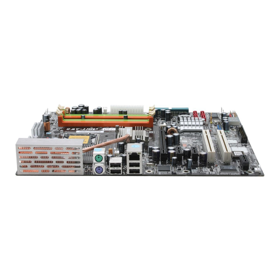
Summary of Contents for Abit AW8
- Page 1 AW8 Series (AW8, AW8-MAX) Intel Pentium 4 System Board Socket 775 User’s Manual 4200-0454-03 Rev. 1.01...
- Page 2 No part of this manual may be reproduced, transmitted or transcribed without the expressed written permission of the manufacturer and authors of this manual. If you do not properly set the motherboard settings, causing the motherboard to malfunction or fail, we cannot guarantee any responsibility. AW8 Series...
-
Page 3: Table Of Contents
Introduction ... 1-1 1-1. Features & Specifications ...1-1 1-2. Layout Diagram ...1-3 Chapter 2. Hardware Setup... 2-1 2-1. Install The Motherboard...2-1 2-2. Install CPU, Heatsink and Fan Assembly ...2-2 2-3. Install System Memory ...2-4 2-4. Connectors, Headers and Switches ...2-6 (1). - Page 4 Appendix C. Install Audio Driver ... C-1 Appendix D. Install BCM LAN Driver ...D-1 Appendix E. Install Sil3132 SATA Driver (AW8-MAX) ... E-1 Appendix F. Install USB 2.0 Driver ... F-1 Appendix G. Install ABIT µGuru Utility ...G-1 Appendix H.
-
Page 5: Chapter 1. Introduction
Delivers up to 8GB/s per direction for 3.5 times more bandwidth than AGP8X 5. ABIT Engineered • ™ ABIT uGuru 2005 Technology (ABIT OC Guru / ABIT EQ / ABIT Flash Menu / ABIT Black Box) • ABIT CPU ThermalGuard •... - Page 6 2x PCI slots • 1x AudioMAX slot • 1x Floppy port • 1x UDMA 100/66/33 connector • 2x SATA connectors (For model AW8-MAX only) • 4x SATA connectors • 2x USB 2.0 headers • 2x IEEE1394b headers (For model AW8-MAX only) •...
-
Page 7: Layout Diagram
Introduction 1-2. Layout Diagram User’s Manual... - Page 8 Chapter 1 AW8 Series...
-
Page 9: Chapter 2. Hardware Setup
2-1. Install The Motherboard Most computer chassis have a base with many mounting holes to allow the motherboard to be securely attached, and at the same time, prevent the system from short circuits. There are two ways to attach the motherboard to the chassis base: 1. -
Page 10: Install Cpu, Heatsink And Fan Assembly
3. Use your right thumb on the bottom-right side of the load plate and lift it up to fully open position. AW8 Series 4. Use your right thumb and forefinger to grasp the CPU package. Be sure to grasp on the edge of the substrate, and face the Pin-1 indicator toward the bottom-left side. - Page 11 9. Place the heatsink and fan assembly onto the socket. Align the four fasteners toward the four mounting holes on the motherboard. It is strongly recommended that you use an air-cooled fan heatsink designed for the LGA775 processor.
-
Page 12: Install System Memory
There are several methods of different DDR2 configurations depending on how the DIMMs are populated on each system memory channel: • [Single Channel]: only one channel is populated. Method DIMM1 512MB 512MB AW8 Series Channel A DIMM2 512MB 512MB Channel B DIMM3 DIMM4... - Page 13 • [Dual Channel Asymmetric]: both channels are populated, but each channel has a different amount of total memory. (Channel A≠Channel B) Method DIMM1 512MB 512MB 256MB 256MB 256MB 256MB 256MB • [Dual Channel Symmetric]: both channels are populated where each channel has the same amount of total memory.
-
Page 14: Connectors, Headers And Switches
WARNING: Always power off the computer and unplug the AC power cord before adding or removing any peripheral or component. Failing to so may cause severe damage to your motherboard and/or peripherals. Plug in the AC power cord only after you have carefully checked everything. -
Page 15: Fan Power Connectors
(2). FAN Power Connectors These connectors each provide power to the cooling fans installed in your system. • CPUFAN1: CPU Fan Power Connector • NBFAN1: Chipset Fan Power Connector • SYSFAN1: System Fan Power Connector • AUXFAN1 ~ 5: Auxiliary Fan Power Connector WARNING: These fan connectors are not jumpers. -
Page 16: Cmos Memory Clearing Header
Pin 1-2 shorted (default): Normal operation. • Pin 2-3 shorted: Clear CMOS memory. WARNING: Turn the power off first (including the +5V standby power) before clearing the CMOS memory. Failing to do so may cause your system to work abnormally or malfunction. AW8 Series... -
Page 17: Wake-Up Header
(4). Wake-up Header These headers use a jumper cap to enable/disable the wake-up function. • USB-PWR1: Pin 1-2 shorted (default): Disable wake-up function support at USB1 port. Pin 2-3 shorted: Enable wake-up function support at USB1 port. • USB-PWR2: Pin 1-2 shorted (default): Disable wake-up function support at USB2 port. Pin 2-3 shorted: Enable wake-up function support at USB2 port User’s Manual... -
Page 18: Back Panel Audio Connection Slot
R.L./R.R. (Rear Left / Rear Right): channel audio system. • S.L./S.R. (Surround Left / Surround Right): right channel in the 7.1 channel audio system. AW8 Series Connects to the rear left and rear right channel in the 7.1 Connects to the surround left and surround... - Page 19 S/PDIF Connection: Along with the motherboard package you can find an fiber cable for S/PDIF connection. • S/PDIF Input Connection: 1. Plug the end with 3.5mm adapter into the [JK1] jack on this daughter-card. (This jack is used for either optical or line input.) 2.
-
Page 20: Front Panel Switches & Indicators Headers
Connects to the Suspend LED cable (if there is one) of chassis front panel. • PWR (Pin 6, 8): Connects to the Power Switch cable of chassis front panel. • PLED (Pin 16, 18, 20): Connects to the Power LED cable of chassis front panel. AW8 Series... -
Page 21: Additional Ieee1394 Port Headers
(7). Additional IEEE1394 Port Headers These headers each provide one additional IEEE1394 port connection through an extension cable and bracket. AW8-MAX: Pin Assignment TPA0 + Ground TPB0 + +12V Pin Assignment TPA0 - Ground TPB0 - +12V Ground User’s Manual... -
Page 22: Additional Usb Port Headers
(8). Additional USB Port Headers These headers each provide 2 additional USB 2.0 ports connection through an USB cable designed for USB 2.0 specifications. AW8 Series Pin Assignment Data0 - Data0 + Ground Pin Assignment Data1 - Data1 + Ground... -
Page 23: Guru Clock Connection Header
Hardware Setup 2-15 (9). GURU Clock Connection Header This header is reserved for connecting ABIT’s exclusive GURU Clock. User’s Manual... -
Page 24: Floppy And Ide Disk Drive Connectors
NOTE: Make sure to configure the “Master” and “Slave” relation before connecting two drives by one single ribbon cable. The red line on the ribbon cable must be aligned with pin-1 on both the IDE port and the hard-drive connector. AW8 Series... -
Page 25: Post Code Display
POST Code in address 80h to find out where the problem lies. This LED device also displays the “POST” Code of AC2005, an “uGuru” chipset developed exclusively by ABIT computer. NOTE: The decimal point lights up when executing the AC2005 POST action. -
Page 26: Serial Ata Connectors
Intel ICH7R chipset. You may configure a disk array by the Intel Matrix Storage Technology RAID Driver option ROM utility. For model “AW8-MAX”, two additional SATA connectors (SATA5 and SATA6 hard drives through the Silicon Image chipset) are provided. You may configure a disk array by the Sil3132 SATA Driver option ROM utility. -
Page 27: Pci Express X16 Slot
Hardware Setup 2-19 (13). PCI Express x16 Slot This slot is used to attach the next generation of graphics architecture. (14). PCI Express x1 Slots These slots are used to attach the next generation of I/O architecture. User’s Manual... -
Page 28: Back Panel Connectors
(15). Back Panel Connectors AW8: AW8-MAX: • IEEE1: Connects to devices of IEEE1394 protocol. (For model AW8-MAX only) • Mouse: Connects to PS/2 mouse. • Keyboard: Connects to PS/2 keyboard. • LAN1: Connects to Local Area Network (For model AW8-MAX only). -
Page 29: Chapter 3. Bios Setup
BIOS Setup Chapter 3. BIOS Setup This motherboard provides a programmable EEPROM that you can update the BIOS utility. The BIOS (Basic Input/Output System) is a program that deals with the basic level of communication between processor and peripherals. Use the BIOS Setup program only when installing motherboard, reconfiguring system, or prompted to “Run Setup”. -
Page 30: Μguru ™ Utility
This item displays the CPU model name installed on this motherboard. Frequency: This item displays the processor speed of the CPU installed on this motherboard. CPU Operating Speed: This item displays the CPU operating speed according to the type and speed of your CPU. You can also select the [User Define] option to enter the manual option. - Page 31 External Clock: This item selects the external clock frequency. Due to the specification limit of the CPU you installed, the speed you set over its standard bus speed is supported, but not guaranteed. Multiplier Factor: This item displays the multiplier factor for the CPU you installed. Estimated New CPU Clock: This item displays an estimated CPU processor speed.
- Page 32 These items display the power cycle statistics for each element. ABIT EQ: Click right-arrow <→> key to switch from OC Guru setup menu to ABIT EQ setup menu: ABIT EQ Beep Control: This item allows you to enable or disable ABIT EQ Beep Control function.
-
Page 33: Temperature Monitoring
Temperature Monitoring: Click <Enter> key to enter its submenu: CPU Temperature/System Temperature/PWM Temperature: These items display the temperature of CPU, System, and Power Module. Shutdown Enable: Use <Space> key to enable system shutdown function. If the CPU/System/PWM’s temperature exceeds the shutdown temperature limit, the system would shutdown automatically. Shutdown Temp.: This items sets the temperature that would shutdown the system automatically in order to prevent system overheats. -
Page 34: Voltage Monitoring
Use <Space> key to enable warning beeps function. If the voltage of corresponding element is higher/lower than the high/low limit, warning beeps will sound. High/Low Limit: These items set the high and low voltage limit. NOTE: The value of high limit must be set above the one of low limit. AW8 Series... -
Page 35: Fan Speed Monitoring
Fan Speed Monitoring: Click <Enter> key to enter its submenu: CPU/NB/SYS/AUX/OTES FAN Speed: These items display the speed of the fans connected to CPU, NB, SYS, AUX1 and AUX2 FAN headers. Shutdown Enable: Use <Space> key to enable system shutdown function. Once the system has detected that the fan speed is lower than the low limit value, system will shutdown automatically. - Page 36 DC Fan Voltage High/Low: These items set the high and low voltage limit that you want to provide the fan with. NOTE: The value of high limit must be set above the one of low limit. AW8 Series FanEQ Group):...
- Page 37 Click <Enter> key to enter its submenu (2 Click <Enter> key to enter its submenu (3 AUX/OTES FanEQ Control: When set to [Enabled], these items control the AUX/OTES fan speed by the following setting combinations. Reference Temperature: This item selects the reference point for taking temperature among the available options of CPU, SYS, and PWM Temperature, but there is only one “CPU Temperature”...
-
Page 38: Standard Cmos Features
NOTE: The items “IDE Channel 3 Master/Slave” and “IDE Channel 4 Master/Slave” appear only when the item “On-Chip SATA” in the “On-Chip IDE Device” menu is set to [Enhanced Mode], or set to [Auto] when SATA ports are connected with devices. AW8 Series... - Page 39 BIOS Setup 3-11 IDE HDD Auto-Detection: This item allows you to detect the parameters of IDE drives by pressing <Enter> key. The parameters will be shown on the screen automatically. IDE Channel 1 Master/Slave, IDE Channel 2 Master/Slave, Extended IDE Drive: When set to [Auto], the BIOS will automatically check what kind of IDE drive you are using.
-
Page 40: Advanced Bios Features
Base Memory: This item displays the amount of base memory installed in the system. The value of the base memory is typically 640K for system with 640K or more memory size installed on the motherboard. Extended Memory: This item displays the amount of extended memory detected during system boot-up. -
Page 41: Cpu Feature
Quick Power On Self Test: When set to [Enabled], this item speeds up the Power On Self Test (POST) after powering on the system. The BIOS shorten or skip some check during the POST. CPU Feature: Click <Enter> key to enter its submenu: Delay Prior to Thermal: This item selects the delay time before thermal activation. - Page 42 CMOS before you can start up the system. But by doing this, you will have to reset all previously set options. MPS Version Ctrl For OS: This item specifies which version of MPS (Multi-Processor Specification) this motherboard will use. Leave this item to its default setting. AW8 Series...
-
Page 43: Advanced Chipset Features
Report No FDD For OS: When set to [Yes], this item allows you to run some older operating system without floppy disk drive. Leave this item to its default setting. Delay IDE Initial (Secs): This item allows the BIOS to support some old or special IDE devices by prolonging this delay time. A larger value will give more delay time to the device for which to initialize and to prepare for activation. - Page 44 PEG Force X1 When set to [Enabled], this item forces the PEG port down to x1 mode. Init Display First: This item selects whether to initiates from “PCI Express Slot” or “PCI Slot” first when system boots up. AW8 Series...
-
Page 45: Integrated Peripherals
BIOS Setup 3-17 3-5. Integrated Peripherals On-Chip IDE Device: Click <Enter> key to enter its submenu: IDE Bus Master: This option enables or disables the IDE bus mastering capability under the DOS environment. On-Chip IDE-1 Controller: This item selects whether to enable or disable the IDE-1 controller. On-Chip SATA Mode: This item determines the mode for on-chip Serial ATA. - Page 46 1 Slave IDE1 IDE1 Primary Master Slave Secondary SATA1 SATA3 NOTE: This option is configurable only when the item [On-Chip SATA] is set to [Combined Mode]. AW8 Series Channel Channel Channel 2 Master 2 Slave 3 Master None None SATA1...
-
Page 47: On-Chip Pci Device
SATA Mode: This item displays the variety modes for SATA Mode. On-Chip PCI Device: Click <Enter> key to enter its submenu: On-Chip USB Controller: This option enables or disables the USB controller. USB 2.0 Controller: This option enables or disables the USB 2.0 controller. USB Keyboard Support: This item allows you to select [BIOS] for using USB keyboard in DOS environment, or [OS] in OS environment. -
Page 48: Onboard Pci Device
This option enables or disables the LAN controller. Invoke Boot Agent: This item allows you to use the boot ROM (instead of a disk drive) to boot-up the system and access the local area network directly. 3-6. Power Management Setup AW8 Series... - Page 49 ACPI Suspend Type: This item selects the type of Suspend mode. [S1(PowerOn-Suspend)]: Enables the Power On Suspend function. [S3(Suspend-To-RAM)]: Enables the Suspend to RAM function. Resume by USB From S3: When set to [Enabled], this item allows you to use a USB device to wake up a system that is in the S3 (STR - Suspend To RAM) state.
- Page 50 If the system’s power is off when AC power failure occurs, it will remain off when power returns. If the system’s power is on when AC power failure occurs, the system will power-on when power returns. AW8 Series...
-
Page 51: Pnp/Pci Configurations
BIOS Setup 3-23 3-7. PnP/PCI Configurations Resources Controlled By: This item configures all of the boot and Plug-and-Play compatible devices. [Auto(ESCD)]: The system will automatically detect the settings. [Manual]: Choose the specific IRQ resources in the “IRQ Resources” menu. IRQ Resources: Click <Enter>... -
Page 52: Load Fail-Safe Defaults
This option protects the BIOS configuration or restricts access to the computer itself. 3-11. Save & Exit Setup This option saves your selections and exits the BIOS setup menu. 3-12. Exit Without Saving This option exits the BIOS setup menu without saving any changes. AW8 Series... -
Page 53: Appendix A. Install Intel Chipset Software Installation Utility
Appendix A. Install Intel Chipset Software Installation Utility NOTE: Please install this Intel Chipset driver first after having installed the Windows operating system. The installation procedures and screen shots in this section are based on Windows XP operating system. For those of other OS, please follow its on-screen instructions. - Page 54 Appendix A AW8 Series...
-
Page 55: Appendix B. Install Intel Matrix Storage Technology Raid Driver
Appendix B. Install Intel Matrix Storage Technology RAID Driver The installation procedures and screen shots in this section are based on Windows XP operating system. For those of other OS, please follow its on-screen instructions. Insert the Driver & Utility CD into CD-ROM drive. - Page 56 Appendix B 5. Click [Next]. 6. Click [Finish] to complete setup. AW8 Series...
-
Page 57: Appendix C. Install Audio Driver
Install Audio Driver Appendix C. Install Audio Driver The installation procedures and screen shots in this section are based on Windows XP operating system. For those of other OS, please follow its on-screen instruction. Insert the Driver & Utility CD into CD-ROM drive, it should execute the installation program automatically. - Page 58 Appendix C AW8 Series...
-
Page 59: Appendix D. Install Bcm Lan Driver
Install BCM LAN Driver Appendix D. Install BCM LAN Driver The installation procedures and screen shots in this section are based on Windows XP operating system. For those of other OS, please follow its on-screen instruction. Insert the Driver & Utility CD into CD-ROM drive, it should execute the installation program automatically. - Page 60 Appendix D AW8 Series...
-
Page 61: Appendix E. Install Sil3132 Sata Driver (Aw8-Max)
Appendix E. Install Sil3132 SATA Driver (AW8-MAX) The installation procedures and screen shots in this section are based on Windows XP operating system. For those of other OS, please follow its on-screen instruction. Insert the Driver & Utility CD into CD-ROM drive, it should execute the installation program automatically. - Page 62 Appendix E 7. Choose [I accept the terms in the license 10. Click [Finish] to complete setup.. agreement], and click [Next]. 8. Click [Next]. 9. Click [Finish]. AW8 Series...
-
Page 63: Appendix F. Install Usb 2.0 Driver
Install USB 2.0 Driver Appendix F. Install USB 2.0 Driver NOTE: The “USB 2.0 Driver” packed in the “Driver & Utility CD” is currently available for Windows 9x and ME only. To install this driver for Windows XP or Windows 2000, you have to download their latest service pack first from Microsoft’s web site. - Page 64 Appendix F AW8 Series...
-
Page 65: Appendix G. Install Abit Μguru Utility
If not, double-click the execution file at the main directory of this CD to enter the installation menu. After entering the installation menu, move your curser to [ABIT Utility] tab. Click [ABIT Guru]. The following screen appears. 1. Click [Next]. 2. Click [Next]. - Page 66 Appendix G AW8 Series...
-
Page 67: Appendix H. Post Code Definition
Appendix H. POST Code Definition AWARD POST Code Definitions POST Description (hex) Test CMOS R/W functionality Early chipset initialization: -Disable shadow RAM -Disable L2 cache (socket 7 or below) -Program basic chipset registers Detect memory -Auto-detection of DRAM size, type and ECC -Auto-detection of L2 cache (socket 7 or below) Expand compressed BIOS code to DRAM Call chipset hook to copy BIOS back to E000 &... - Page 68 4. On MP platform, adjust the cacheable range to smaller one in case the cacheable ranges between each CPU are not identical Initialize USB Test all memory (clear all extended memory to 0) Clear password according to H/W jumper (Optional) AW8 Series...
- Page 69 Display number of processors (multi-processor platform) Display PnP logo Early ISA PnP initialization -Assign CSN to every ISA PnP device Initialize the combined Trend Anti-Virus code (Optional Feature) Show message for entering AWDFLASH.EXE from FDD (optional) 1. Initialize Init_Onboard_Super_IO 2. Initialize Init_Onbaord_AUDIO Okay to enter Setup utility;...
- Page 70 Update keyboard LED & typematic rate 1. Build MP table 2. Build & update ESCD 3. Set CMOS century to 20h or 19h 4. Load CMOS time into DOS timer tick 5. Build MSIRQ routing table Boot attempt (INT 19h) AW8 Series...
- Page 71 AC2005 POST Code Definition: POST Description (hex) 8.1. Start power on sequence 8.2. Enable ATX power supply 8.3. ATX power supply ready 8.4. DDR voltage ready 8.5. Setup PWM for CPU core voltage 8.6. Assert PWM for CPU core voltage 8.7.
- Page 72 Appendix H Appendix H AW8 Series AW8 Series...
-
Page 73: Appendix I. Troubleshooting (Need Assistance?)
Appendix I. Troubleshooting (Need Assistance?) Q & A: Q: Do I need to clear the CMOS before I use a new motherboard to assemble my new computer system? A: Yes, we highly recommend that you clear the CMOS before installing a new motherboard. Please move the CMOS jumper from its default 1-2 position to 2-3 for a few seconds, and then back. - Page 74 If you still cannot boot up: Try installing another brand/model VGA card and see if the system will start. If it still does not start, note the VGA card model, motherboard model, Bios identification number, and CPU on the technical support form (refer to main instructions), and describe the problem in the space provided.
- Page 75 To fill in this “Technical Support Form”, refer to the step-by-step instructions given below: . MODEL: Note the model number given in your user’s manual. Example: AW8 Series . Motherboard model number (REV): Note the motherboard model number labeled on the motherboard as “REV:*.**”. Example: REV: 1.00 .
-
Page 76: Technical Support Form
" Contact Person: ) E-mail Address: Model Motherboard Model No. OS/Application Hardware Name IDE1 IDE2 IDE1 CD-ROM-Drive IDE2 System Memory ADD-ON CARD Problem Description: AW8 Series ( Phone Number: # Fax Number: BIOS ID # DRIVER REV Brand Specifications Appendix I... -
Page 77: Appendix J. How To Get Technical Support
Also please make sure you have the latest drivers from your peripheral card makers! 3. Check the ABIT Technical Terms Guide and FAQ on our website. We are trying to expand and make the FAQs more helpful and information rich. Let us know if you have any suggestions. - Page 78 They should have reasonable return or refund policies. How they serve you is also a good reference for your next purchase. 6. Contacting ABIT. If you feel that you need to contact ABIT directly you can send email to the ABIT technical support department. First, please contact the support team for the branch office closest to you.
- Page 79 ABIT Computer (U.K.) Corporation Ltd. Unit 3, 24-26 Boulton Road, Stevenage, Herts SG1 4QX, UK Tel: 44-1438-228888 Fax: 44-1438-226333 E-mail: sales@abitcomputer.co.uk AMOR Computer B.V. (ABIT's European Office) Jan van Riebeeckweg 15, 5928LG, Venlo, The Netherlands Tel: 31-77-3204428 Fax: 31-77-3204420 Sales: sales@abit.nl Web Site: http://www.abit.nl...
- Page 80 Please contact the reseller from whom you bought the product. You should be able to get RMA service there. 9. Reporting Compatibility Problems to ABIT. Because of tremendous number of email messages we receive every day, we are forced to give greater weight to certain types of messages than to others.
Need help?
Do you have a question about the AW8 and is the answer not in the manual?
Questions and answers