Table of Contents
Advertisement
Available languages
Available languages
Quick Links
Advertisement
Chapters
Table of Contents

Subscribe to Our Youtube Channel
Related Manuals for Marmitek IR Control 10 XTRA


Summary of Contents for Marmitek IR Control 10 XTRA
- Page 1 R Control 10 XTRA IR Control 10 XTRA ™ USER MANUAL GEBRAUCHSANLEITUNG GUIDE UTILISATEUR MODO DE EMPLEO 33?? MANUALE D’ISTRUZIONI 43?? GEBRUIKSAANWIJZING 53?? 20562/ 20121126 • IR CONTROL 10 XTRA ™ ALL RIGHTS RESERVED MARMITEK ©...
-
Page 3: Table Of Contents
In case of improper usage or if you have altered and repaired the product yourself, all guarantees expire. Marmitek does not accept responsibility in the case of improper usage of the product or when the product is used for purposes other than specified. -
Page 4: Introduction
1. INTRODUCTION Congratulations on your purchase of the IR Control 10 XTRA™. With it you can extend the IR (infrared) signals of remote controls. The IR Control 10 XTRA™ makes it possible to operate A/V devices while these are in a closed cupboard or when your A/V equipment is out of sight. -
Page 5: Connections
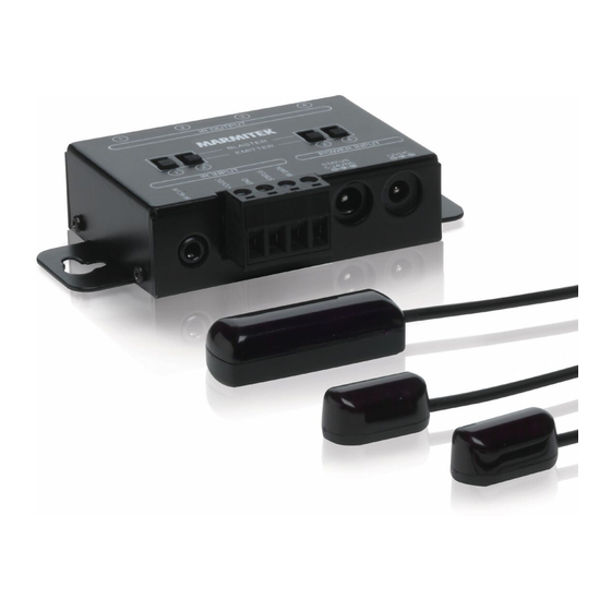
The IR Control 10 XTRA™ is made up of three main components; (1) IR Receiver The IR Receiver receives infrared commands from your remote control and sends these onto the IR Module. (2) IR Module The IR Module receives infrared commands from the IR Receiver, processes them and sends them onto all connected IR Extender Cables. -
Page 6: Power Input
Note! The sticky strip may lead to discolouration or leave glue residues on certain surfaces. 5.2 Placing the IR extension cable with one blaster LED Marmitek recommends the use of IR blaster LEDs because they can operate multiple A/V devices at the same time and they are very easy to install. Use... -
Page 7: Installation Of The Ir Extension Cable With Emitter Leds
the supplied IR extension cable with emitter LEDs only as solution if one or more devices cannot be operated (see chapter 5.3). Place the IR blaster LED in the cabinet of the A/V devices you want to operate. With a correct placement one blaster LED can operate all A/V devices placed in the same compartment. -
Page 8: Locating The Ir Module
You can now operate your A/V equipment via the IR Control 10 XTRA™ through the closed cabinet doors! If the IR Control 10 XTRA is not reacting in a correct way, try experimenting with the placement of the IR receiver and/or IR extension cables (emitter or... -
Page 9: Advanced Installation
Note; check the technical documentation of your equipment to decide whether the IR module of the IR control 10 XTRA can be connected directly. Most IR cables use a 3.5mm mono jack connector where the tip is used for... -
Page 10: Frequently Asked Questions
Relocate the IR LED so that less infrared light is received via the IR window. Do you have other questions that have not been resolved by the above information? Please go to www.marmitek.com... -
Page 11: Technical Data
8. TECHNICAL DATA IR receiver Frequency range: 30-60 KHz IR reception range: ± 10 meters IR reception angle: 90º (+45º/-45º from centre) Cable length: 3 meters, extendable up to 300 meters IR reception indication: YES, purple indication LED Status indication: YES, green indication LED Receiver dimensions: 40 x 13 x 11mm... -
Page 12: Optional
The LEDs of the IR extension cables with 2 emitter LEDs have to be stuck to the A/V device(s) you want to operate. See datasheets of the IR emitter LEDs on www.marmitek.com. Environmental Information for Customers in the European Union... - Page 13 übernimmt bei einer falschen Verwendung des Produkts oder bei einer anderen Verwendung des Produktes als für den vorgesehenen Zweck keinerlei Produkthaftung. Marmitek übernimmt für Folgeschäden keine andere Haftung als die gesetzliche Produkthaftung. Dieses Produkt ist kein Spielzeug. Außer Reichweite von Kindern halten.
-
Page 14: Einführung
Herzlichen Glückwunsch zum Erwerb des IR Control 10 XTRA™. Mit diesem Set können Sie IR (Infrarot-) Signale von Fernbedienungen verlängern. Das IR Control 10 XTRA™ ermöglicht es A/V Geräte zu bedienen, während diese sich in einem geschlossenen Schrank oder außer Sichtweite befinden. -
Page 15: Anschlüsse
Das IR Control 10 XTRA™ besteht aus drei Hauptbestandteilen; (1) IR Empfänger Der IR Empfänger fängt Infrarot-Befehle Ihrer eigenen Fernbedienung auf und sendet diese an das IR Modul weiter. (2) IR Modul Das IR Modul empfängt die Infrarot-Befehle vom IR Empfänger, verarbeitet diese und gibt sie an alle angeschlossene IR- Verlängerungskabel weiter. -
Page 16: Power Input
4.2 POWER Input 12VDC: Speisungsadapter für das IR Modul (enthalten) 5VDC/200mA STATUS: Speisungsadapter für Statussignal (nicht enthalten) 5-24VDC of 5-12VAC 4.3 IR Output 1 – 4: Vier Mini Buchsenanschlüsse für den Anschluss der IR Verlängerungskabel EMITTER / BLASTER: Jeder Ausgang kann einzeln geschaltet werden, um Blaster oder Emitter LED’s anzuschließen. -
Page 17: Anbringung Des Ir Verlängerungskabels Mit Einem Blaster Led
5.2 Anbringung des IR Verlängerungskabels mit einem Blaster LED Marmitek empfiehlt die Verwendung von IR Blaster LEDs weil diese mehrere AV Geräte zugleich bedienen können und Installation kinderleicht ist. Verwenden Sie das enthaltene IR Verlängerungskabel mit Emitter LEDs nur als Problemlösung, wenn ein oder mehr Geräte nicht bedient werden können (sehen Sie Kapitel 5.3). -
Page 18: Installation Des Ir Moduls
mit einer Taschenlampe auf die Frontseite scheinen und das Fenster des IR Sensors suchen. Alle IR LEDs haben eine selbstklebende Folie, womit sie auf die IR Fenster Ihrer A/V Geräte befestigt werden. Testen Sie zunächst die Position und die Betriebsfähigkeit der IR LED, bevor Sie diese definitiv an das IR Fenster Ihres A/V Geräts kleben. -
Page 19: Verfeinerte Installation
A/V Geräte unmittelbar von der Fernbedienung ein Infrarot- Kommando empfangen können. Das könnte nämlich zu Bedienungsfehlern führen. Sie können nunmehr Ihre A/V Geräte über die IR Control 10 XTRA durch geschlossene Schranktüren hindurch bedienen! Experimentieren Sie mit der Anbringung des IR Empfängers oder IR Verlängerungskabels (Emitter oder Blaster), wenn die IR Control 10... -
Page 20: Avr Verbindungskabel Anschließen
Blaster LED) ist dann überflüssig. Achtung; Schauen Sie in der technischen Dokumentation Ihrer Geräte nach, ob das IR Modul des IR Control 10 XTRA direkt angeschlossen werden kann. Die meisten IR Kabel verwenden einen 3.5 mm Mono Buchsenanschluss, wobei der Ausgang für die "IR Daten“ und der Mantel für "GND“... -
Page 21: Technische Daten
8. TECHNISCHE DATEN IR Empfänger Frequenzbereich: 30-60 KHz IR Empfänger Reichweite: ± 10 Meter IR Empfang Winkel: 90º (+45º/-45º ab Mitte) Kabellänge: 3 Meter, bis auf 300 Meter zu verlängern IR Empfänger Anzeige: Ja, lila Anzeige LED Statusanzeige: Ja, grüne Anzeige LED Maße Empfängerkubus: 40 x 13 x 11mm IR Modul... -
Page 22: Zusätzlich Erhältlich
Geräte bedienen kann. Aufstellung des IR Blaster kann bezüglich der IR LED’s weitaus ungenauer geschehen. Sehen Sie die Datenblätter des IR Empfängers unter www.marmitek.com. IR Verlängerungskabel mit 2 Emitter LED’s (Art.-Nr. 08145) Die IR Verlängerungskabel mit 1 Emitter LEDs müssen an das A/V Gerät, das Sie bedienen möchten, geklebt werden. - Page 23 Marmitek se dégage de toute responsabilité dans le cas d’une utilisation impropre du produit ou d’une utilisation autre que celle pour laquelle le produit est destiné. Marmitek se dégage de toute responsabilité en cas de dommage conséquent, autre que la responsabilité...
-
Page 24: Introduction
1. INTRODUCTION Merci d’avoir acheté le IR Control 10 XTRA™. Il vous permet de prolonger les signaux IR (infrarouge) des télécommandes. Le IR Control 10 XTRA™ permet de commander des appareils A/V lorsqu'ils sont dans un meuble fermé ou lorsque vos appareils A/V sont hors de vue. -
Page 25: Connexions
Le IR Control 10 XTRA™ se compose de trois parties principales ; (1) Le Récepteur IR Le Récepteur IR reçoit des ordres infrarouges de votre télécommande et les transmet vers le IR Module. (2) Le Module IR Le Module IR reçoit les ordres infrarouges du récepteur IR, les traite et les transmet vers tous les câbles d'extension IR connectés. -
Page 26: Entrée D'alimentation
4.2 Entrée d'ALIMENTATION 12VDC: Adaptateur secteur pour le Module IR (fourni), 5VDC/200mA STATUT : Adaptateur secteur pour le signal de STATUT (non fourni), 5- 24VDC ou 5-12VAC 4.3 Sortie IR 1 – 4 : quatre mini sorties jack pour la connexion de câbles d'extension IR. EMETTEUR / BLASTER: chaque sortie est individuellement commutable pour connecter des LEDs blaster ou des LEDs émetteur. -
Page 27: Installation Du Câble D'extension Ir Avec Une Led Blaster
5.2 Installation du câble d'extension IR avec une LED blaster Marmitek conseille l'utilisation de LEDs blaster IR, parce qu'ils permettent de commander simultanément plusieurs appareils A/V et en plus ils sont faciles à installer. N'utilisez le câble d'extension IR avec LEDs émetteur fourni que pour résoudre un problème si un ou plusieurs appareils ne peuvent pas être... -
Page 28: Installation Du Module Ir
électrique. 5.6 Testez le fonctionnement du produit Si le IR Control 10 XTRA™ est correctement connecté, le voyant sur le Récepteur IR clignote lorsque vous appuyez sur une touche de la télécommande (infrarouge) et que vous la dirigez vers le Récepteur IR. -
Page 29: Installation Avancée
Vous pouvez maintenant commander vos appareils A/V par le biais du IR Control 10 XTRA™ à travers les portes fermées d'un meuble ! Si le IR Control 10 XTRA ne réagit pas correctement, expérimentez alors avec la position du Récepteur IR et/ou des Câble d'extension IR (émetteur ou blaster). -
Page 30: Foire Aux Questions
IR (avec LED émetteur ou blaster) est alors superflue. Attention : Consultez la documentation technique de vos appareils A/V afin de déterminer si le Module IR du IR Control 10 XTRA peut être connecté directement. La plupart des câbles IR utilisent une prise jack mono 3,5mm dont l'extrémité... -
Page 31: Caractéristiques Techniques
8. CARACTÉRISTIQUES TECHNIQUES Récepteur IR Plage de fréquence 30-60 KHz Portée de réception IR : ± 10 mètres Angle de réception IR : 90º (+45º/-45º depuis le centre) Longueur du câble : 3 mètres, peut être rallongé jusqu'à 300 mètres Indicateur de réception IR : OUI, voyant LED violet Indicateur de statut :... -
Page 32: Disponible En Option
Les câbles d'extension IR avec 2 LEDs émetteur doivent être collés sur l'appareil A/V que vous souhaitez commander. Voir les fiches de données de la LED émetteur IR sur le site internet www.marmitek.com. Informations environnementales pour les clients de l’Union européenne La directive européenne 2002/96/CE exige que l’équipement sur lequel est apposé... -
Page 33: Avisos De Seguridad
En caso de uso indebido o modificaciones y reparaciones montados por su mismo, la garantía se caducará. En caso de uso indebido o impropio, Marmitek no asume ninguna responsabilidad para el producto. Marmitek no asume ninguna responsabilidad para daños que resultan del uso impropio, excepto según la... -
Page 34: Introducción
1. INTRODUCCIÓN Felicitaciones por la compra del IR Control 10 XTRA™. Con este podrá prolongar las señales IR (infrarrojas) de su mando a distancia. Con el IR IR Control 10 XTRA™ se pueden controlar aparatos A/V, aunque se encuentren dentro de un armario cerrado o fuera del alcance de la vista. -
Page 35: Conexiones
El IR Control 10 XTRA™ se compone de tres partes principales: (1) El Receptor IR El Receptor IR recibe los comandos infrarrojos de su propio mando a distancia y los transmite al IR Module. (2) El IR Module El IR Module recibe los comandos infrarrojos del Receptor IR, los elabora y los transmite a todos los Cables de Extension IR conectados. -
Page 36: Entrada Alimentación
5.2 Colocación del cable de extensión IR con un blaster LED Marmitek aconseja el uso del Led del blaster IR porque este puede accionar varios dispositivos A/V al mismo tiempo y gracias a ello la instalación es muy... -
Page 37: Instalación Del Cable De Extensión Ir Con Emisores Led
sencilla. Usa el cable de extensión IR suministrado con emisores LED solamente como solución para problemas si uno o más dispositivos no pueden ser accionados (véase capítulo 5.3). Coloca el LED del blaster IR en el armario del dispositivo A/V que quieras accionar. -
Page 38: Colocación Del Módulo Ir
Ahora puedas accionar tu dispositivo A/V mediante el IR Control 10 XTRA™, ¡a través de las puertas cerradas del armario! Si el IR Control 10 XTRA no reacciona de una manera adecuada, pruebe entonces con la colocación del Receptor IR y/ o el cable de extensión IR... -
Page 39: Instalación Avanzada
Atención; Comprueba la documentación técnica de tu dispositivo para determinar si el Módulo IR del IR Control 10 XTRA puede conectarse directamente. La mayoría de los cables IR usa una conexión mono jack de 3.5mm que se usa para los “Datos IR” y la manga para “GND”. -
Page 40: Preguntas Frecuentes
Algunas ventanillas IR de set-top boxes o de boxes de satélite son muy sensibles. Estos dispositivos pueden recibir demasiada radiación infrarroja, lo que influye en el funcionamiento. Cambia el lugar del LED IR de manera que entra menos luz infrarroja en la ventanilla IR. ¿Tiene más preguntas? Vistia www.marmitek.com... -
Page 41: Datos Tecnicos
8. DATOS TECNICOS Receptor IR Rango alcance: 30-60 KHz Recepción IR alcance: ± 10 Metros Ángulo de recepción IR: 90º (+45º/-45º desde el centro) Longitud de cable: 3 metros, prolongable hasta llegar a 300 metros Indicación recepción IR: SÍ, LED indicación morada Indicación estado: SÍ, LED indicación verde Dimensiones del receptor: 40 x 13 x 11mm... -
Page 42: También A La Venta
Los cables de extensión IR con 2 emisores LED deben conectarse a un dispositivo A/V que quieras accionar. Véanse las hojas de datos de los LED del emisor IR en www.marmitek.com. Información medioambiental para clientes de la Unión Europea La Directiva 2002/96/CE de la UE exige que los equipos que lleven este símbolo en el propio aparato y/o en su embalaje no deben eliminarse junto con otros residuos urbanos no seleccionados. - Page 43 Marmitek declina ogni responsabilità per i danni derivanti da un utilizzo non appropriato del prodotto o da utilizzo diverso da quello per cui il prodotto è stato creato. Marmitek declina ogni responsabilità per danni consequenziali ad eccezione della responsabilità civile sui prodotti.
-
Page 44: Introduzione
1. INTRODUZIONE Congratulazioni con il vostro acquisto dell’ IR Control 10 XTRA™. Con Marmitek IR Control 10 XTRA™ potete ampliare i segnali infrarossi (IR) dei vostri telecomandi e controllare apparecchi audio/video anche se collocati in un mobile chiuso o fuori vista. -
Page 45: Collegamenti
(1) Ricevitore IR Il ricevitore IR riceve i comandi a infrarossi dal vostro telecomando e li trasmette all’IR Module. (2) IR Module L’IR Module riceve i comandi a infrarossi dal ricevitore IR, li elabora e li trasmette a tutti i cavi di prolunga IR collegati. (3) Prolunga IR con due LED emittenti o un LED blaster La prolunga IR riceve i commandi a infrarossi del modulo IR e li converte a segnali a infrarossi tramite i LED IR o blaster IR. -
Page 46: Ingresso Power
4.2 Ingresso POWER 12VDC: adattatore di alimentazione per il modulo IR (fornito), 5VDC/200mA STATUS: adattatore di alimentazione per il segnale di Stato (non fornito), 5-24VDC o 5-12VAC 4.3 Uscita IR 1 – 4: quattro uscite mini-jack per il collegamento dei cavi di prolunga IR. EMITTER/BLASTER: ogni uscita può... -
Page 47: Collocamento Della Prolunga Ir Tramite Un Led Blaster
5.2 Collocamento della prolunga IR tramite un LED blaster Marmitek raccomanda l’uso dei LED blaster visto che questo tipo di LED è in grado di comandare contemporaneamente più apparecchi A/V e perché è di facile installazione. Solo usare la prolunga IR con i LED emittenti in caso di problemi con il comando di uno o più... -
Page 48: Collocamento Del Modulo Ir
5.6 Collaudare il funzionamento del prodotto Se il IR Control 10 XTRA™ è stato collegato correttamente, la spia sul ricevitore IR lampeggerà quando si preme un tasto del telecomando (a infrarossi) mentre è puntato verso il ricevitore IR. -
Page 49: Installazione Avanzata
Nel caso che l’IR Control 10 XTRA non reagisca in modo giusto, si deve sperimentare il posizionamento del ricevitore IR e/o dei cavi di prolunga IR (emittente o blaster). Un altro posizionamento può dare risultati migliori. 6. INSTALLAZIONE AVANZATA 6.1 Collegare più ricevitori IR Quando si desidera comandare le apparecchiature A/V da più... -
Page 50: Domande Frequenti
Attenzione: controllare la documentazione tecnica delle apparecchiature per determinare se il modulo IR dell’IR Control 10 XTRA può essere collegato direttamente. La maggioranza dei cavi IR è corredata di connettori da 3.5mm jack mono e si usa l’estremità per i dati IR (“IR Data”) ed il rivestimento per “GND”... -
Page 51: Caratteristiche Tecniche
8. CARATTERISTICHE TECNICHE Ricevitore IR Portata di frequenza: 30-60 KHz Portata di ricezione IR: ± 10 metri Angolo di ricezione IR: 90º (+45º/-45º dal centro) Lunghezza del cavo: 3 metri, aumentabile fino ai 300 metri Indicazione di ricezione IR: si, LED di segnalazione viola Indicazione di stato: si, LED di segnalazione verde Dimensioni blocco ricevitore:... -
Page 52: Opzioni Disponibili
Il LED blaster richiede un posizionamento meno preciso rispetto ai LED IR. Vedere i fogli dati del LED blaster sul sito www.marmitek.com. Prolunga IR con due LED emittenti (No. articolo 08145) I cavi di prolunga IR con 2 LED emittenti vanno attaccati sull’apparecchio A/V da comandare. - Page 53 Bij oneigenlijk gebruik, zelf aangebrachte veranderingen of reparaties, komen alle garantiebepalingen te vervallen. Marmitek aanvaardt geen productaansprakelijkheid bij onjuist gebruik van het product of door gebruik anders dan waarvoor het product is bestemd. Marmitek aanvaardt geen aansprakelijkheid voor volgschade anders dan de wettelijke productaansprakelijkheid.
-
Page 54: Introductie
1. INTRODUCTIE Gefeliciteerd met uw aankoop van de IR Control 10 XTRA™. Hiermee kunt u de IR (infrarood) signalen van afstandsbedieningen verlengen. De IR Control 10 XTRA™maakt het mogelijk om A/V apparaten te bedienen terwijl deze in een gesloten kast staan of wanneer uw A/V apparaten uit het zicht staan. -
Page 55: Aansluitingen
(1) IR ontvanger De IR ontvanger vangt infrarood commando’s op van uw eigen afstandsbediening en stuurt deze door naar de IR Module. (2) IR Module De IR Module ontvangt de infrarood commando’s van de IR ontvanger, verwerkt deze en stuurt ze door naar alle aangesloten IR verlengkabels. (3) IR verlengkabel met twee emitter LED’s of één blaster LED De IR verlengkabel ontvangt de infrarood commando’s van de IR Module en zet deze via de IR LED’s of IR blasters om naar infrarood signalen. -
Page 56: Power Input
4.2 POWER input 12VDC: Voedingsadapter voor de IR Module (meegeleverd), 5VDC/200mA STATUS: Voedingsadapter voor het Status signaal (niet meegeleverd), 5- 24VDC of 5-12VAC 4.3 IR output 1 – 4: vier mini jack uitgangen voor het aansluiten van IR verlengkabels. EMITTER / BLASTER: iedere uitgang is apart schakelbaar om blaster of emitter LED’s aan te sluiten. -
Page 57: Plaatsing Van De Ir Verlengkabel Met Één Blaster Led
5.2 Plaatsing van de IR verlengkabel met één blaster LED Marmitek adviseert het gebruik van IR blaster LED’s omdat deze meerdere A/V apparaten gelijkertijd kan bedienen en de installatie hiervan zeer eenvoudig is. Gebruik de meegeleverde IR verlengkabel met emitter LED’s enkel als probleem oplosser indien één of meerdere apparaten niet bediend... -
Page 58: Plaatsing Van De Ir Module
Sluit de deurtjes van uw kastje en voorkom dat de A/V apparatuur ook direct van de afstandsbediening een infrarood commando kunnen ontvangen, dit kan namelijk tot bedieningsproblemen leiden. U kunt nu uw A/V apparatuur bedienen via de IR Control 10 XTRA™ door gesloten kast deurtjes heen! -
Page 59: Geavanceerde Installatie
Indien de IR Control 10 XTRA niet op juiste manier reageert experimenteer dan met de plaatsing van de IR Ontvanger en/ of IR Verlengkabels (emitter of blaster). Een andere plaatsing kan een beter eindresultaat opleveren. 6. GEAVANCEERDE INSTALLATIE 6.1 Meerdere IR Ontvangers aansluiten Wilt u de A/V apparatuur vanuit meerdere ruimtes kunnen bedienen kunt u tot maximaal 6 IR Ontvangers in parallel aansluiten op de IR Module. -
Page 60: Veel Gestelde Vragen
Let op; Controleer de technische documentatie van uw apparatuur om te bepalen of de IR Module van de IR Control 10 XTRA direct aangesloten kan worden. De meeste IR kabels gebruiken een 3.5mm mono jack aansluiting waarbij het uiteinde wordt gebruikt voor de “IR Data” en de mantel voor “GND”. -
Page 61: Technische Gegevens
8. TECHNISCHE GEGEVENS IR ontvanger Frequentie bereik: 30-60 KHz IR ontvangst bereik: ± 10 Meter IR ontvangst hoek: 90º (+45º/-45º vanaf center) Kabellengte: 3 meter, verlengbaar tot 300 meter IR ontvangst indicatie: JA, paarse indicatie LED Status indicatie: JA, groene indicatie LED Afmeting ontvanger blokje: 40 x 13 x 11mm IR Module... -
Page 62: Optioneel Verkrijgbaar
Plaatsing van de IR blaster is ten opzichte van de IR LED’s veel minder nauwkeurig. Zie datasheets van de IR Blaster LED op www.marmitek.com. IR verlengkabel met twee emitter LED’s (Artnr. 08145) De IR verlengkabels met 2 emitter LED’s moeten op het A/V apparaat geplakt worden dat u wilt bedienen. - Page 63 Direttiva 2002/95/CE del Parlamento europeo e del Consiglio del 27 gennaio 2003 sulla restrizione dell'uso di determinate sostanze pericolose nelle apparecchiature elettriche ed elettroniche Bij deze verklaart Marmitek BV, dat deze IR CONTROL 10 XTRA™ voldoet aan de essentiële eisen en aan de overige relevante bepalingen van Richtlijnen:...
Need help?
Do you have a question about the IR Control 10 XTRA and is the answer not in the manual?
Questions and answers