Table of Contents
Advertisement
Motherboard
AMD Socket AM2
User's Manual
For more information:
www.abit.com.tw
AMD Socket AM2
ATX Motherboard
NB: NVIDIA C51XE
SB: NVIDIA MCP55PXE
2GHz HT
Dual DDR2 800 DIMM Slots
NVIDIA SLI Technology
Dual PCI-E X16 Slots
Dual GbE LAN
IEEE 1394a
6x SATA 3Gb/s with
RAID 0/1/0+1/5/JBOD
Fatal1ty Guru™ Technology
ABIT OTES GT™ Technology
7.1 Channel HD Audio
Advertisement
Table of Contents

Related Manuals for Abit FATAL1TY AN9 32X


Summary of Contents for Abit FATAL1TY AN9 32X
-
Page 1: Amd Socket Am2
2GHz HT Dual DDR2 800 DIMM Slots NVIDIA SLI Technology Dual PCI-E X16 Slots Dual GbE LAN IEEE 1394a 6x SATA 3Gb/s with RAID 0/1/0+1/5/JBOD For more information: Fatal1ty Guru™ Technology www.abit.com.tw ABIT OTES GT™ Technology 7.1 Channel HD Audio... - Page 2 The Fatal1ty name, Fatal1ty logos and the Fatal1ty likeness are trademarks of Fatal1ty, Inc. All rights reserved. Built to Kill is a trademark of PWX, LLC. Ltd. © 2006 Universal ABIT Co., All other trademarks are the property of their respective owners.
-
Page 3: Table Of Contents
2.6.7 GURU Panel Connection Header ......... 2-23 2.7 Onboard Status Display .............. 2-24 2.7.1 POST Code Displayer............2-24 2.7.2 Power Source Indicators ............ 2-25 2.8 Connecting I/O Devices.............. 2-26 3. BIOS Setup............... 3-1 ™ 3.1 µGuru Utility................3-2 3.1.1 OC Guru ................3-2 3.1.2 ABIT EQ ................3-4... - Page 4 5. Appendix ................5-1 5.1 POST Code Definitions ..............5-1 5.1.1 AWARD POST Code Definitions..........5-1 5.1.2 AC2005 POST Code Definitions..........5-4 5.2 Troubleshooting (How to Get Technical Support?) ......5-5 5.2.1 Q & A .................5-5 5.2.2 Technical Support Form ............5-8 5.2.3 Universal ABIT Contact Information ........5-9...
-
Page 5: Introduction
1. Introduction 1.1 Fatal1ty FATAL1TY STORY Who knew that at age 19, I would be a World Champion PC gamer. When actually played competitive billiards in professional tournaments and won four or five games off guys who played at the highest level. - Page 6 LIVIN’ LARGE Since my first big tournament wins, I have been a “Professional Cyberathlete”, traveling the world and livin’ large with lots of International media coverage on outlets such as MTV, ESPN and G4TV to name only a few. It's unreal - it's crazy. I’m living a dream by playing video games for a living.
-
Page 7: Features & Specifications
Gigabit Ethernet IEEE 1394 • Supports 2 Ports IEEE 1394a at 400Mb/s transfer rate Audio • ABIT AudioMAX HD 7.1 CH • Supports auto jack sensing and optical S/PDIF In/Out Expansion Slots • 2x PCI Express x16 slots • 2x PCI Express x1 slots •... - Page 8 • 2x RJ-45 Gigabit LAN ports • 4x USB 2.0 ports RoHS Compliancy • 100% Lead-free process and RoHS compliancy Miscellaneous • ATX form factor (305mm x 245mm) Specifications and information contained herein are subject to change without notice. For more information: www.abit.com.tw...
-
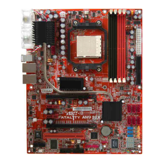
Page 9: Motherboard Layout
1.3 Motherboard Layout... - Page 10 For more information: www.abit.com.tw...
-
Page 11: Hardware Setup
2. Hardware Setup In this chapter we will elaborate all the information you need upon installing this motherboard to your computer system. ※ Always power off the computer and unplug the AC power cord before adding or removing any peripheral or component. Failing to so may cause severe damage to your motherboard and/or peripherals. -
Page 12: Checking Jumper Settings
To install this motherboard: 1. Locate all the screw holes on motherboard chassis base. 2. Place all the studs or spacers needed on the chassis base and have them tightened. 3. Face the motherboard’s I/O ports toward the chassis’s rear panel. -
Page 13: Cmos Memory Clearing Header And Backup Battery
2.3.1 CMOS Memory Clearing Header and Backup Battery The time to clear the CMOS memory occurs when (a) the CMOS data becomes corrupted, (b) you forgot the supervisor or user password preset in the BIOS menu, (c) you are unable to boot-up the system because the CPU ratio/clock was incorrectly set in the BIOS menu, or (d) whenever there is modification on the CPU or memory modules. - Page 14 CMOS Backup Battery: An onboard battery saves the CMOS memory to keep the BIOS information stays on even after disconnected your system with power source. Nevertheless, this backup battery exhausts after some five years. Once the error message like “CMOS BATTERY HAS FAILED” or “CMOS checksum error”...
-
Page 15: Wake-Up Headers
2.3.2 Wake-up Headers These headers use a jumper cap to enable/disable the wake-up function. • PS2-PWR1: Pin 1-2 shorted (Default): Disable wake-up function support at Keyboard/Mouse port. Pin 2-3 shorted: Enable wake-up function support at Keyboard/Mouse port. • USB-PWR1: Pin 1-2 shorted (Default): Disable wake-up function support at USB1 port. Pin 2-3 shorted: Enable wake-up function support at USB1 port. -
Page 16: Connecting Chassis Components
2.4 Connecting Chassis Components 2.4.1 ATX Power Connectors These connectors provide the connection from an ATX power supply. As the plugs from the power supply fit in only one orientation, find the correct one and push firmly down into these connectors. -
Page 17: Front Panel Switches & Indicators Headers
2.4.2 Front Panel Switches & Indicators Headers This header is used for connecting switches and LED indicators on the chassis front panel. Watch the power LED pin position and orientation. The mark “+” align to the pin in the figure below stands for positive polarity for the LED connection. -
Page 18: Fan Power Connectors
2.4.3 FAN Power Connectors These connectors each provide power to the cooling fans installed in your system. • CPUFAN1: CPU Fan Power Connector • SYSFAN1: System Fan Power Connector • AUXFAN1~4: Auxiliary Fan Power Connector ※ These fan connectors are not jumpers. DO NOT place jumper caps on these connectors. -
Page 19: Installing Hardware
2.5 Installing Hardware ※ DO NOT scratch the motherboard when installing hardware. An accidentally scratch of a tiny surface-mount component may seriously damage the motherboard. 2.5.1 CPU Socket AM2 ※ DO NOT touch or bend the delicate pins on the CPU whenever you are holding it. The installation procedures vary with different types of CPU fan-and-heatsink assembly. - Page 20 4. Place the heatsink and fan assembly onto the retention frame. Match the heatsink clip with socket mounting-lug. Hook the spring clip to the mounting-lug. 5. On the other side, push the retention clip straight down to lock into the plastic lug on the retention frame.
-
Page 21: Ddr2 Memory Slots
2.5.2 DDR2 Memory Slots This motherboard provides four 240-pin DIMM slots for Dual Channel DDR2 800 memory modules with memory expansion size up to 8GB. To reach the performance of Dual Channel DDR2, the following rules must be obeyed: • For a 2-DIMM dual-channel installation: Populate DIMM modules of the same type and size on slots [DIMM1]+[DIMM2], or slots [DIMM3]+[DIMM4]. - Page 22 To install system memory: 1. Power off the computer and unplug the AC power cord before installing or removing memory modules. 2. Locate the DIMM slot on the board. 3. Hold two edges of the DIMM module carefully, keep away of touching its connectors.
-
Page 23: Pci Express X16 Add-On Slots (Install Graphics Card)
2.5.3 PCI Express X16 Add-on Slots (Install Graphics Card) These slots support the connections of graphics cards that comply with PCI Express specifications. This motherboard provides dual PCI-Express X16 slots for one or two graphics cards installation: One PCIE graphics card installation (Normal Mode): Insert your PCIE graphics card into [PCIEXP1] slot. - Page 24 I/O bracket to the first and last screw holes. Leave the three screw holes in between unscrewed. 2. Place Abit’s exclusive SLI FAN assembly “SLIpstream” atop the two graphics cards. installing supporting bracket, you may secure the fan assembly now with the three screws removed from the I/O bracket.
- Page 25 SLI supporting bracket. 6. Connect the power plug from the SLI FAN assembly either to the three-leaded fan-power connector your motherboard, or directly to the ATX12V power supply. For more information: www.abit.com.tw 2-15...
-
Page 26: Audiomax Connection Slot
2.5.4 AudioMAX Connection Slot This slot provides the audio input/output connection over the rear I/O part through an add-on daughter-card. Find your “AudioMAX” daughter-card and its driver in the motherboard package. • S/PDIF Out: This connector provides an S/PDIF-Out connection through optical fiber to digital multimedia devices. - Page 27 • FP-AUDIO1: This header provides the connection to audio connector at front panel. This header provides the front panel connection for HD (High Definition) Audio, yet for AC’97 Audio CODEC connection, you must carefully check the pin assignment before connecting from the front panel module. An incorrect connection may cause malfunction or even damage the motherboard.
- Page 28 3. Click “Disabled front panel jack detection”, and then click “OK” to confirm. S/PDIF Connection: In the motherboard package you can find one audio daughter-card and one optical-fiber cable. • S/PDIF Input Connection: 1. Remove the rubber protection-cap. Attach one end of the optical cable with the 3.5mm Optical-to-Stereo adapter, and have it plugged into the [Line-In] jack on this daughter-card.
-
Page 29: Connecting Peripheral Devices
2.6 Connecting Peripheral Devices 2.6.1 Floppy and IDE Disk Drive Connectors The FDC1 connector connects up to two floppy drives with a 34-wire, 2-connector floppy cable. Connect the single end at the longer length of ribbon cable to the FDC1 on the board, the two connectors on the other end to the floppy disk drives connector. -
Page 30: Serial Ata Connectors
2.6.2 Serial ATA Connectors Each SATA connector serves as one single channel to connect one SATA device by a thin SATA cable. The RAID 0/1/0+1/5/JBOD configuration is also possible through the combination of disk arrays through these SATA connectors: To connect SATA device: 1. -
Page 31: Additional Usb 2.0 Port Headers
2.6.3 Additional USB 2.0 Port Headers Besides the 4x USB 2.0 ports located at rear I/O part, this motherboard also features 3x more USB 2.0 headers onboard. Each header supports 2x additional USB 2.0 ports by connecting bracket or cable to the rear I/O panel or the front-mounted USB ports of your chassis. Pin Assignment Pin Assignment Data0 -... -
Page 32: Pci Express X1 Add-On Slots
2.6.5 PCI Express X1 Add-on Slots These slots provide the connection of add-on cards that comply with PCI Express specifications. 2.6.6 PCI Add-on Slots This slot provides the connection of add-on cards that comply with PCI specifications. 2-22... -
Page 33: Guru Panel Connection Header
2.6.7 GURU Panel Connection Header This header is reserved for connecting ABIT’s exclusive GURU Panel. For more information, please refer to the included GURU Panel Installation Guide. 2-23... -
Page 34: Onboard Status Display
POST Code in address 80h to find out where the problem lies. This LED device also displays the “POST” Code of AC2005, an “uGuru” chipset developed exclusively by Universal ABIT. ※ The decimal point lights up during the AC2005 POST action. -
Page 35: Power Source Indicators
2.7.2 Power Source Indicators These indicators work as a reminding device to display the power status of this motherboard with power source connected. • 5VSB: Lights On: Your ATX power supplier is connected with power source, and its power switch is on. -
Page 36: Connecting I/O Devices
Mouse: Connects to PS/2 mouse. • Keyboard: Connects to PS/2 keyboard. • LAN1/LAN2: Connects to Local Area Network. • USB1/USB2: Connects to USB devices such as scanner, digital speakers, monitor, mouse, keyboard, hub, digital camera, joystick etc. For more information: www.abit.com.tw 2-26... -
Page 37: Bios Setup
3. BIOS Setup This motherboard provides a programmable EEPROM so that you can update the BIOS utility. The BIOS (Basic Input/Output System) is a program that deals with the basic level of communication between processor and peripherals. Use the BIOS Setup program only when installing motherboard, reconfiguring system, or prompted to “Run Setup”. -
Page 38: Μguru Utility
™ 3.1 µGuru Utility There are two setup menus in this µGuru utility. You may switch between these two by clicking the left or right arrow key on keyboard: 3.1.1 OC Guru µGuru Utility V1.00C OC Guru AMD Athlon(tm) 64 X2 Dual Core Processor 3800+ Item Help ►... - Page 39 User Define: ※ The wrong settings of the multiplier and external clock in certain circumstances may cause CPU damage. Setting the working frequency higher than the PCI chipset or processor specs, may cause abnormal memory module functioning, system hangs, hard disk drive data lose, abnormal functioning of the VGA card, or abnormal functioning with other add-on cards.
-
Page 40: Abit Eq
F10:Save ESC:Exit These items display the power cycle statistics for each element. 3.1.2 ABIT EQ Click right-arrow <→> key to switch from OC Guru setup menu to ABIT EQ setup menu: µGuru Utility V1.00C ABIT EQ ABIT EQ Beep Control Enabled Item Help ►... -
Page 41: Temperature Monitoring
Temperature Monitoring Click <Enter> key to enter its submenu: µGuru Utility V1.00C ABIT EQ Temperature Monitoring Reading Shutdown Shutdown Beep Beep Enable Temp. Enable Temp. (*)CPU Temperature 34°C/93°F (*) 85°/185°F 75°C/167°F ° (*)System Temperature 29°C/84°F ( ) 65° C/149°F (*) 55°C/131°F... - Page 42 Voltage Monitoring Click <Enter> key to enter its submenu: µGuru Utility V1.00C ABIT EQ Voltage Monitoring Reading Shutdown Beep High Enable Enable Limit Limit (*)CPU Core Voltage 1.40 V (*) 1.60 V (*)DDR2 Voltage 1.80 V ( ) 2.20 V 1.50 V...
-
Page 43: Fan Speed Monitoring
Fan Speed Monitoring Click <Enter> key to enter its submenu: µGuru Utility V1.00C ABIT EQ Fan Speed Monitoring Reading Shutdown Beep Enable Enable Limit (*)CPU FAN Speed 7440 RPM 300 RPM ( )SYS FAN Speed 300 RPM ( )AUX1 FAN Speed... - Page 44 FanEQ Control µGuru Utility V1.00C ABIT EQ FanEQ Control ► CPU FanEQ Control Press Enter Item Help ►► ► SYS FanEQ Control Press Enter ► AUX1 FanEQ Control Press Enter ► AUX2 FanEQ Control Press Enter ► AUX3 FanEQ Control Press Enter ►...
- Page 45 ※ The value of high limit must be set above the one of low limit. Click <ESC> key to exit this menu and move back to the main menu of “ABIT EQ”. Move the down-arrow key to the next item (SYS FanEQ Control), and then click <Enter> key to enter its submenu: µGuru Utility V1.00C...
- Page 46 Click <ESC> key to exit this menu and move back to the main menu of “ABIT EQ”. Move the down-arrow key to the next item (AUX1 FanEQ Control ~ AUX4 FanEQ Control), and then click <Enter> key to enter its submenu: µGuru Utility V1.00C...
-
Page 47: Standard Cmos Features
3.2 Standard CMOS Features Phoenix – Award BIOS CMOS Setup Utility Standard CMOS Features Date (mm:dd:yy) Mon. Jul 03 2006 Item Help Time (hh:mm:ss) 12 : 34 : 56 ► IDE Channel 1 Master None ► IDE Channel 1 Slave None ►... - Page 48 IDE Channel 1 Master/Slave, IDE Channel 3~8 Master: Click <Enter> key to enter its submenu: Phoenix – Award BIOS CMOS Setup Utility IDE Channel 1 Master IDE HDD Auto-Detection Press Enter Item Help IDE Channel 1 Master Auto Access Mode Auto Capacity 0 MB...
- Page 49 Head This item configures the number of read/write heads. Precomp This item displays the number of cylinders at which to change the write timing. Landing Zone This item displays the number of cylinders specified as the landing zone for the read/write heads.
-
Page 50: Advanced Bios Features
3.3 Advanced BIOS Features Phoenix – Award BIOS CMOS Setup Utility Advanced BIOS Features Quick Power on Self Test Enabled Item Help ► Hard Disk Boot Priority Press Enter First Boot Device Floppy Second Boot Device Hard Disk Third Boot Device CDROM Boot Other Device Enabled... - Page 51 Boot Up NumLock Status This item determines the default state of the numeric keypad at system booting up. [On]: The numeric keypad functions as number keys. [Off]: The numeric keypad functions as arrow keys. Security Option This item determines when the system will prompt for password - every time the system boots or only when it enters the BIOS setup.
-
Page 52: Advanced Chipset Features
3.4 Advanced Chipset Features Phoenix – Award BIOS CMOS Setup Utility Advanced Chipset Features K8<->NB HT Speed Auto Item Help K8<->NB HT Width Auto NB-->SB HT Speed Auto NB<->SB HT Width Auto PCI Express bus(SB) Hyperclk GPU NB<->SB Reference clock Auto PCI Express bus(NB) Hyperclk GPU... - Page 53 DRAM Configuration: Click <Enter> key to enter its submenu. You may manually set the DRAM timing parameters through the following sub-items, or leave them at their default settings according to the SPD (Serial Presence Detect) data stored in the DRAM. Phoenix –...
-
Page 54: Integrated Peripherals
3.5 Integrated Peripherals Phoenix – Award BIOS CMOS Setup Utility Integrated Peripherals ► OnChip IDE/RAID Function Press Enter Item Help Init Display First PCIEXP1 OnChip USB V1.1+V2.0 - USB Keyboard Support - USB Mouse Support OnChip Audio Controller Auto OnChip LAN1 Controller Auto OnChip LAN2 Controller Auto... -
Page 55: Ide Function Setup
IDE Function Setup: Click <Enter> key to enter its submenu: Phoenix – Award BIOS CMOS Setup Utility IDE Function Setup IDE 1 Controller Enabled Item Help IDE DMA transfer access Enabled IDE HDD Block Mode Enabled Serial-ATA Controller All Enabled ↓↑→←:Move Enter:Select +/-/PU/PD:Value F10:Save ESC:Exit F1:General Help F5: Previous Values F6: Fail-Safe Defaults... -
Page 56: Raid Configuration
RAID Configuration: Click <Enter> key to enter its submenu: Phoenix – Award BIOS CMOS Setup Utility RAID Configuration RAID Function Disabled Item Help X - Serial-ATA 1 RAID Disabled X - Serial-ATA 2 RAID Disabled X - Serial-ATA 3 RAID Disabled X - Serial-ATA 4 RAID Disabled... - Page 57 USB Keyboard Support Select [BIOS] for the legacy operating system (such as DOS) that does not support USB keyboard. USB Mouse Support Select [BIOS] for the legacy operating system (such as DOS) that does not support USB mouse. OnChip Audio Controller This option enables or disables the audio controller.
-
Page 58: Power Management Setup
3.6 Power Management Setup Phoenix – Award BIOS CMOS Setup Utility Power Management Setup ACPI Suspend Type S3(Suspend-To-RAM) Item Help - USB Resume from S3 Disabled Power Button Function Instant-Off Wakeup by PME# of PCI Enabled Wakeup by OnChip LAN Enabled Wakeup by Alarm Disabled... - Page 59 Wakeup by OnChip LAN When set to [Enabled], you can remotely wake up a PC in Soft-Off condition via a LAN card that support the wake up function. Wakeup by Alarm When set to [Enabled], you can set the date and time you would like the Soft-Off PC to power-on in the “Date (of Month) Alarm”...
-
Page 60: Pnp/Pci Configurations
※ Do not forget your password, or you will have to clear the CMOS and reset all parameters in order to utilize this function again. Hot Key Power ON This item powers on the system by pressing <Ctrl> key plus one of each function key (<F1> ~ <F12>) simultaneously. - Page 61 IRQ Resources Click <Enter> key to enter its submenu: This item sets each system interrupt to either [PCI Device] or [Reserved]. Phoenix – Award BIOS CMOS Setup Utility - IRQ Resources IRQ-4 assigned to Reserved Item Help IRQ-5 assigned to PCI Device IRQ-7 assigned to PCI Device...
-
Page 62: Load Fail-Safe Defaults
This option protects the BIOS configuration or restricts access to the computer itself. 3.11 Save & Exit Setup This option saves your selections and exits the BIOS setup menu. 3.12 Exit Without Saving This option exits the BIOS setup menu without saving any changes. For more information: www.abit.com.tw 3-26... -
Page 63: Driver & Utility Cd
• [Utility]: Click to enter the utilities installation menu. • [ABIT Utility]: Click on this tab to enter the menu for installing utilities exclusively developed by ABIT. • Browse CD]: Click to browse the contents of this “Driver & Utility CD”. -
Page 64: Nvidia Nforce Chipset Driver
4.1 nVidia nForce Chipset Driver To install this driver: Click on the [Drivers] tab in the installation menu screen. Click the [nVidia nForce Chipset Driver]. The following screen appears: Follow the prompts on the screen to complete installation. Restart the system for the driver to take effect. ※... -
Page 65: Realtek Hd Audio Driver
4.2 Realtek HD Audio Driver To install this driver: Click on the [Drivers] tab in the installation menu screen. Click the [Realtek HD Audio Driver] item. The following screen appears: Follow the prompts on the screen to complete installation. Restart the system for the driver to take effect. ※... -
Page 66: Silicon Image 3132 Raid Driver
4.3 Silicon Image 3132 RAID Driver To install this driver: Click on the [Drivers] tab in the installation menu screen. Click the [Silicon Image 3132 RAID Driver] item. The following screen appears: Follow the prompts on the screen to complete installation. Restart the system for the driver to take effect. -
Page 67: Cool'n'quiet Driver
4.4 Cool’n’Quiet Driver To install this driver: Click on the [Drivers] tab in the installation menu screen. Click the [Cool’n’Quiet Driver] item. The following screen appears: Follow the prompts on the screen to complete installation. Restart the system for the driver to take effect. - Page 68 After the system restarted, open the “Power Options” from the control panel and choose the power scheme “Minimal Power Management” to enable Cool ‘n’ Quiet. ※ For Windows 2000 or ME system, an AMD Cool ‘n’ Quiet tab will appear under “Power Options”...
-
Page 69: Usb 2.0 Driver
To install this utility: Click on the [ABIT Utility] tab in the installation menu screen. Click the [ABIT Guru] item. The following screen appears: Follow the prompts on the screen to complete installation. -
Page 70: Nvraid Floppy Disk
Floppy Disk to create another one. To install this utility: Click on the [ABIT Utility] tab in the installation menu screen. Click the [Generate NVRaid Floppy Disk[32bit]]. The following screen appears: Insert one blank floppy disk to the selected floppy drive and click [Build]. -
Page 71: Appendix
5. Appendix 5.1 POST Code Definitions 5.1.1 AWARD POST Code Definitions POST Description (hex) Test CMOS R/W functionality Early chipset initialization: -Disable shadow RAM -Disable L2 cache (socket 7 or below) -Program basic chipset registers Detect memory -Auto-detection of DRAM size, type and ECC -Auto-detection of L2 cache (socket 7 or below) Expand compressed BIOS code to DRAM Call chipset hook to copy BIOS back to E000 &... - Page 72 Early PCI Initialization: -Enumerate PCI bus number. -Assign memory & I/O resource -Search for a valid VGA device & VGA BIOS, and put it into C000:0 1. If Early_Init_Onboard_Generator is not defined Onboard clock generator initialization. Disable respective clock resource to empty PCI & DIMM slots. 2.
- Page 73 Program chipset registers according to items described in Setup & Auto-configuration table 1. Assign resources to all ISA PnP devices 2. Auto assign ports to onboard COM ports if the corresponding item in Setup is set to “AUTO” 1. Initialize floppy controller 2.
-
Page 74: Ac2005 Post Code Definitions
5.1.2 AC2005 POST Code Definitions POST Description (hex) Power On Sequence 8.1. Start power on sequence 8.2. Enable ATX power supply 8.3. ATX power supply ready 8.4. DDR voltage ready 8.5. Setup PWM for CPU core voltage 8.6. Assert PWM for CPU core voltage 8.7. -
Page 75: Troubleshooting (How To Get Technical Support?)
5.2 Troubleshooting (How to Get Technical Support?) 5.2.1 Q & A Q: Do I need to clear the CMOS before I use a new motherboard to assemble my new computer system? A: Yes, we highly recommend that you clear the CMOS before installing a new motherboard. Please move the CMOS jumper from its default 1-2 position to 2-3 for a few seconds, and then back. - Page 76 Q: How to get a quick response for my request on technical support? A: Please carry out a simple troubleshooting before sending “Technical Support Form”: System boot-up fails after the system had been assembled: Check the motherboard’s supporting specifications first to see if all the key components attached in your system can meet.
- Page 77 See the next page for a blank Technical Support Form, or visit our website to fill in the form on line (http://www.abit.com.tw/page/en/contact/technical.php). Q. Is the motherboard dead? Do I need to return it to where I bought from or go...
-
Page 78: Technical Support Form
5.2.2 Technical Support Form Region: E-mail: First name: Last Name: Subject: Motherboard: BIOS Version: CPU: Memory brand: Memory size: Memory configuration: Graphics card: Graphics driver version: Power supply maker: Power supply wattage: Storage devices: Optical devices: Other devices: Operating system: Problem description:... -
Page 79: Universal Abit Contact Information
5.2.3 Universal ABIT Contact Information Taiwan Head Office Austria, Czech, Romania, Bulgaria, Slovakia, Croatia, Bosnia, Serbia, Universal ABIT Co., Ltd. Macedonia, Slovenia No. 323, Yang Guang St., Neihu, Universal ABIT Austria Computer Taipei, 114, Taiwan GmbH Tel: 886-2-8751-3380 Schmalbachstrasse 5, A-2201 Gerasdorf /... - Page 80 Johnathan “Fatal1ty” Wendel P/N: 4310-0000-25 Rev. 2.00...
Need help?
Do you have a question about the FATAL1TY AN9 32X and is the answer not in the manual?
Questions and answers