
Related Manuals for Abit Fatal1ty AA8XE


Summary of Contents for Abit Fatal1ty AA8XE
- Page 1 Intel Pentium 4 System Board Socket 775 User’s Manual For more information: www.abit.com.tw 4200-0433-01 Rev. 1.00...
- Page 2 If you do not properly set the motherboard settings, causing the motherboard to malfunction or fail, we cannot guarantee any responsibility. The Fatal1ty name, Fatal1ty logos and the Fatal1ty likeness are trademarks of Fatal1ty, Inc.
-
Page 3: Table Of Contents
Fatal1ty...1-1 1-2. Features & Specifications ...1-3 1-3. Layout Diagram ...1-5 Chapter 2. Hardware Setup... 2-1 2-1. Install The Motherboard...2-1 2-2. Install CPU, Heatsink and Fan Assembly...2-3 2-3. Install System Memory ...2-5 2-4. Connectors, Headers and Switches ...2-7 (1). ATX Power Input Connectors...2-7 (2). - Page 4 Install Audio Driver ... C-1 Appendix D. Install LAN Driver ...D-1 Appendix E. Install USB 2.0 Driver ... E-1 Appendix F. Install ABIT µGuru Utility ... F-1 Appendix G. POST Code Definition ...G-1 Appendix H. Troubleshooting (Need Assistance?)...H-1 Appendix I.
-
Page 5: Chapter 1. Introduction
Introduction Chapter 1. Introduction 1-1. Fatal1ty FATAL1TY STORY Who knew that at age 19, I would be a World Champion PC gamer. When I was 13, I actually played competitive billiards in professional tournaments and won four or five games off guys who played at the highest level. - Page 6 I can win with them – and making them available to fellow gamers. Gaming is my life, and many fellow gamers around the world are also some of my best friends, so giving back to the gaming community is really important to me. Johnathan “Fatal1ty” Wendel Fatal1ty AA8XE...
-
Page 7: Features & Specifications
Supports Dual channel DDR2-533/400 non-ECC un-buffered memory • Supports maximum memory capacity up to 4GB 4. ABIT Engineered ™ • ABIT uGuru Technology (ABIT OC Guru/ABIT EQ/ABIT Flash Menu/ABIT Black Box) • ABIT ThermalGuard • ABIT TweakGuard ™ • ABIT OTES cooling Technology (Enhanced Version) •... - Page 8 • 4x SATA 150 connectors • 2x USB 2.0 headers • 2x IEEE1394 headers 10. Back Panel I/O • ABIT Dual OTES • 1x PS/2 keyboard, 1 x PS/2 mouse • 1x IEEE1394 • 4x USB 2.0 • 1x RJ-45 LAN (Gigabit), 1 x RJ-45 LAN (10/100) 11.
-
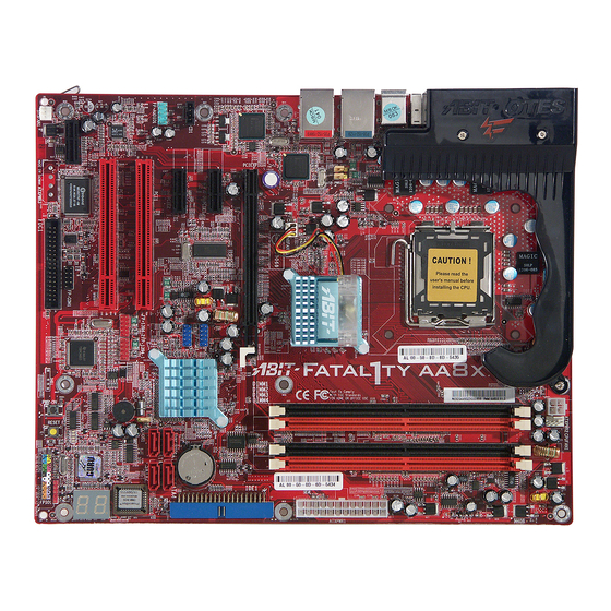
Page 9: Layout Diagram
Introduction 1-3. Layout Diagram User’s Manual... - Page 10 Chapter 1 For more information: www.abit.com.tw Fatal1ty AA8XE...
-
Page 11: Chapter 2. Hardware Setup
2-1. Install The Motherboard Most computer chassis have a base with many mounting holes to allow the motherboard to be securely attached, and at the same time, prevent the system from short circuits. There are two ways to attach the motherboard to the chassis base: 1. - Page 12 3. Place all the studs or spacers needed on the chassis base, and then have them tightened. 4. Line up all the screw holes on the motherboard with those studs or spacers on the chassis. 5. Tighten all the screws.
-
Page 13: Install Cpu, Heatsink And Fan Assembly
Hardware Setup 2-2. Install CPU, Heatsink and Fan Assembly In order to protect the contact pins, please pay attention to these notices: 1. A maximum 20 cycles of CPU installation is recommended. 2. Never touch the contact pins with fingers or any object. - Page 14 9. Place the heatsink and fan assembly onto the socket. Align the four fasteners toward the four mounting holes on the motherboard. Fatal1ty AA8XE For detailed information on how to install your heatsink and fan assembly, please refer to the instruction manual came packed with the heatsink and fan assembly you bought.
-
Page 15: Install System Memory
Hardware Setup 2-3. Install System Memory The Intel 925XE Express Chipset MCH memory interface is designed with Flex Memory Technology supporting single-channel or dual-channel DDR2 memory configurations. • To reach the optimum performance in dual-channel configurations, install identical DDR2 DIMM pairs for each channel. - Page 16 DIMM module. ATTENTION: Static electricity can damage the electronic components of the computer or optional boards. Before starting these procedures, ensure that you are discharged of static electricity by touching a grounded metal object briefly. Fatal1ty AA8XE Channel A DIMM2 256MB...
-
Page 17: Connectors, Headers And Switches
WARNING: Always power off the computer and unplug the AC power cord before adding or removing any peripheral or component. Failing to so may cause severe damage to your motherboard and/or peripherals. Plug in the AC power cord only after you have carefully checked everything. -
Page 18: Fan Power Connectors
CPUFAN1: CPU Fan Power Connector • NBFAN1: Chipset Fan Power Connector • SYSFAN1: System Fan Power Connector • OTESFAN1, OTESFAN2: OTES Fan Power Connector WARNING: These fan connectors are not jumpers. DO NOT place jumper caps on these connectors. Fatal1ty AA8XE Chapter 2... -
Page 19: Cmos Memory Clearing Header
Hardware Setup (3). CMOS Memory Clearing Header This header uses a jumper cap to clear the CMOS memory. • Pin 1-2 shorted (default): Normal operation. • Pin 2-3 shorted: Clear CMOS memory. WARNING: Turn the power off first (including the +5V standby power) before clearing the CMOS memory. -
Page 20: Wake-Up Header
Pin 1-2 shorted (default): Disable wake-up function support at USB1 port. Pin 2-3 shorted: Enable wake-up function support at USB1 port. • USB-PWR2: Pin 1-2 shorted (default): Disable wake-up function support at USB2 port. Pin 2-3 shorted: Enable wake-up function support at USB2 port Fatal1ty AA8XE Chapter 2... -
Page 21: Front Panel Audio Connection Header
Hardware Setup (5). Front Panel Audio Connection Header This header provides the connection to audio connector at front panel. Pin Assignment MIC2 L (Microphone 2 Left) MIC2 R (Microphone 2 Right) FRO-R (Front Right) F_IO_SEN (Front I/O Sensor) FRO-L (Front Left) Pin Assignment AGND (Analog Ground) AVCC (Analog VCC Power) -
Page 22: Back Panel Audio Connection Slot
S.L./S.R. (Surround Left / Surround Right): right channel in the 7.1 channel audio system. Fatal1ty AA8XE Connects to the center and subwoofer channel in the 7.1 channel audio Connects to the rear left and rear right channel in the 7.1... - Page 23 Hardware Setup S/PDIF Connection: Along with the motherboard package you can find an fiber cable for S/PDIF connection. • S/PDIF Input Connection: 1. Plug the end with 3.5mm adapter into the [JK1] jack on this daughter-card. (This jack is used for either optical or line input.)
-
Page 24: Front Panel Com1 Connection Header
2-14 (7). Front Panel COM1 Connection Header This header provides one additional COM1 port connection through an extension cable and bracket. Fatal1ty AA8XE Pin Assignment DCD (Data Carrier Detect) TXD (Transfer-Data) RTS (Request-to-Send) RI (Ring-Indicator) Chapter 2 Pin Assignment RXD (Receive-Data) -
Page 25: Front Panel Switches & Indicators Headers
Hardware Setup (8). Front Panel Switches & Indicators Headers This header is used for connecting switches and LED indicators on the chassis front panel. Watch the power LED pin position and orientation. The mark “+” align to the pin in the figure below stands for positive polarity for the LED connection. -
Page 26: Additional Ieee1394 Port Headers
2-16 (9). Additional IEEE1394 Port Headers These headers each provide one additional IEEE1394 port connection through an extension cable and bracket. Fatal1ty AA8XE Pin Assignment TPA0 + Ground TPB0 + +12V Chapter 2 Pin Assignment TPA0 - Ground TPB0 -... -
Page 27: Additional Usb Port Headers
Hardware Setup (10). Additional USB Port Headers These headers each provide 2 additional USB 2.0 ports connection through an USB cable designed for USB 2.0 specifications. Pin Assignment Data0 - Data0 + Ground 2-17 Pin Assignment Data1 - Data1 + Ground User’s Manual... -
Page 28: Guru Clock Connection Header
2-18 Chapter 2 (11). GURU Clock Connection Header This header is reserved for connecting ABIT’s exclusive GURU Clock. (12). Internal Audio Connectors These connectors connect to the audio output of internal CD-ROM drive or add-on card. Fatal1ty AA8XE... -
Page 29: Floppy And Ide Disk Drive Connectors
Hardware Setup 2-19 (13). Floppy and IDE Disk Drive Connectors The FDC1 connector connects up to two floppy drives with a 34-wire, 2-connector floppy cable. Connect the single end at the longer length of ribbon cable to the FDC1 on the board, the two connectors on the other end to the floppy disk drives connector. -
Page 30: Post Code Display
POST Code in address 80h to find out where the problem lies. This LED device also displays the “POST” Code of AC2003, an “uGuru” chipset developed exclusively by ABIT computer. NOTE: The decimal point lights up when executing the AC2003 POST action. -
Page 31: Serial Ata Connectors
These connectors are provided to attach one Serial ATA device at each channel via Serial ATA cable. This motherboard provides RAID 0 and RAID 1 configuration for Serial ATA hard drives through the Intel ICH6R chipset. You may configure a disk array by the Intel Application Accelerator RAID option ROM utility. -
Page 32: Pci Express X16 Slot
2-22 Chapter 2 (16). PCI Express x16 Slot This slot is used to attach the next generation of graphics architecture. (17). PCI Express x1 Slots These slots are used to attach the next generation of I/O architecture. Fatal1ty AA8XE... -
Page 33: Onboard Switches
Hardware Setup (18). Onboard Switches • PWR-ON: Press this button to power on the system. • RESET: Press this button to reset the system. 2-23 User’s Manual... -
Page 34: Status Indicator
SUS: This LED lights up when the system is in suspend mode. • HD: This LED lights up when the hard drive is activating. • VCC: This LED lights up when the system power is on. Fatal1ty AA8XE Chapter 2... -
Page 35: Back Panel Connectors
Hardware Setup (20). Back Panel Connectors • IEEE1: Connects to devices of IEEE1394 protocol. • Mouse: Connects to PS/2 mouse. • Keyboard: Connects to PS/2 keyboard. • LAN1: Connects to Gigabit Local Area Network. • LAN2: Connects to 10/100Mbps Local Area Network. •... - Page 36 2-26 Chapter 2 For more information: www.abit.com.tw Fatal1ty AA8XE...
-
Page 37: Chapter 3. Bios Setup
BIOS Setup Chapter 3. BIOS Setup This motherboard provides a programmable EEPROM that you can update the BIOS utility. The BIOS (Basic Input/Output System) is a program that deals with the basic level of communication between processor and peripherals. Use the BIOS Setup program only when installing motherboard, reconfiguring system, or prompted to “Run Setup”. -
Page 38: Μguru Utility
This item displays the CPU model name installed on this motherboard. Frequency: This item displays the processor speed of the CPU installed on this motherboard. CPU Operating Speed: This item displays the CPU operating speed according to the type and speed of your CPU. You can also select the [User Define] option to enter the manual option. - Page 39 BIOS Setup External Clock: This item selects the external clock frequency. Due to the specification limit of the CPU you installed, the speed you set over its standard bus speed is supported, but not guaranteed. Multiplier Factor: This item displays the multiplier factor for the CPU you installed. NOTE: Some processors might have this multiplier factor locked, so there is no way to choose a higher multiplier factor.
- Page 40 These items display the power cycle statistics for each element. ABIT EQ: Click right-arrow <→> key to switch from OC Guru setup menu to ABIT EQ setup menu: ABIT EQ Beep Control: This item allows you to enable or disable ABIT EQ Beep Control function.
-
Page 41: Temperature Monitoring
BIOS Setup Temperature Monitoring: Click <Enter> key to enter its submenu: CPU Temperature/System Temperature/PWM Temperature: These items display the temperature of CPU, System, and Power Module. Shutdown Enable: Use <Space> key to enable system shutdown function. If the CPU/System/PWM’s temperature exceeds the shutdown temperature limit, the system would shutdown automatically. -
Page 42: Voltage Monitoring
Use <Space> key to enable warning beeps function. If the voltage of corresponding element is higher/lower than the high/low limit, warning beeps will sound. High/Low Limit: These items set the high and low voltage limit. NOTE: The value of high limit must be set above the one of low limit. Fatal1ty AA8XE Chapter 3... -
Page 43: Fan Speed Monitoring
BIOS Setup Fan Speed Monitoring: Click <Enter> key to enter its submenu: CPU/NB/SYS/AUX1/AUX2 FAN Speed: These items display the speed of the fans connected to CPU, NB, SYS, AUX1 and AUX2 FAN headers. Shutdown Enable: Use <Space> key to enable system shutdown function. Once the system has detected that the fan speed is lower than the low limit value, system will shutdown automatically. - Page 44 DC Fan Voltage High/Low: These items set the high and low voltage limit that you want to provide the fan with. NOTE: The value of high limit must be set above the one of low limit. Fatal1ty AA8XE Chapter 3...
-
Page 45: Standard Cmos Features
BIOS Setup 3-2. Standard CMOS Features This section contains the basic configuration parameters of the BIOS. These parameters include date, hour, VGA card, FDD, and HDD settings. Date (mm:dd:yy): This item sets the date you specify (usually the current date) in the format of [Month], [Date], and [Year]. Time (hh:mm:ss): This item sets the time you specify (usually the current time) in the format of [Hour], [Minute], and [Second]. - Page 46 B, or both. Leave this item to its default [Disabled] setting if you are not using this Japanese standard floppy drive. Halt On: This item determines whether the system stops if an error is detected during system boot-up. Fatal1ty AA8XE...
- Page 47 Base Memory: This item displays the amount of base memory installed in the system. The value of the base memory is typically 640K for system with 640K or more memory size installed on the motherboard. Extended Memory: This item displays the amount of extended memory detected during system boot-up.
-
Page 48: Advanced Bios Features
When set to [Enabled], this item limits the CPUID maximum value to 3, which is usually required for older OS like Windows NT4.0. Leave this item to its default [Disabled] settings for OS like Windows XP. NX BIOS Control When set to [Disabled], this NX features flag will be forced to return to 0. Fatal1ty AA8XE... - Page 49 BIOS Setup 3-13 Back to Advanced BIOS Features Setup Menu: Hyper-Threading Technology This item is used to enable the functionality of the processor with Hyper-Threading Technology and will appear only when using such processor. The Hyper-Threading Technology helps your PC work more efficiently by maximizing processor resources and enabling a single processor to run two separate threads of software simultaneously, bringing forth greater performance and system responsiveness when running multiple applications at once.
- Page 50 3-14 Chapter 3 MPS Version Ctrl For OS: This item specifies which version of MPS (Multi-Processor Specification) this motherboard will use. Leave this item to its default setting. Report No FDD For OS: When set to [Yes], this item allows you to run some older operating system without floppy disk drive.
-
Page 51: Advanced Chipset Features
BIOS Setup 3-4. Advanced Chipset Features DRAM Timing Selectable: This item sets the optimal timings for the following four items, depending on the memory module you are using. The default setting “By SPD” configures these four items by reading the contents in the SPD (Serial Presence Detect) device. -
Page 52: Pci Express Root Port Func
Back to Advanced Chipset Features Setup Menu: Init Display First: This item selects whether to initiates from “PCI Express Slot” or “PCI Slot” first when system boots up. Game Accelerator: This item enables or disables the Game Accelerator. Fatal1ty AA8XE Chapter 3... -
Page 53: Integrated Peripherals
BIOS Setup 3-17 3-5. Integrated Peripherals OnChip IDE Device: Click <Enter> key to enter its submenu: IDE Bus Master: This option enables or disables the IDE bus mastering capability under the DOS environment. On-Chip IDE-1 Controller: This item selects whether to enable or disable the IDE-1 controller. SATA Mode: This item determines the mode for on-chip Serial ATA. - Page 54 SATA1 SATA3 NOTE: This option is configurable only when the item [On-Chip Serial ATA] is set to [Combined Mode]. SATA Port: This item displays the variety modes for SATA Ports. Fatal1ty AA8XE Channel Channel Channel 1 Master 1 Slave 2 Master...
-
Page 55: Onchip Pci Device
BIOS Setup OnChip PCI Device: Click <Enter> key to enter its submenu: OnChip USB Controller: This option enables or disables the USB controller. USB 2.0 Controller: This option enables or disables the USB 2.0 controller. USB Keyboard Support Via: This item allows you to select [BIOS] for using USB keyboard in DOS environment, or [OS] in OS environment. -
Page 56: Superio Device
This item determines which I/O addresses the onboard Serial Port controller will access. [Auto]: The system automatically selects an I/O address for the onboard Serial Port. [3F8/IRQ4, 2F8/IRQ3, 3E8/IRQ4, 2E8/IRQ3]: Allows you to manually select an I/O address for the onboard Serial Port. [Disabled]: Disables the onboard Serial Port. Fatal1ty AA8XE... -
Page 57: Onboard Pci Device
BIOS Setup 3-21 Onboard PCI Device: Click <Enter> key to enter its submenu: IEEE 1394 Controller: This option enables or disables the IEEE 1394 controller. Onboard LAN Controller: This option enables or disables the LAN controller. LAN Boot ROM: This item allows you to use the boot ROM (instead of a disk drive) to boot-up the system and access the local area network directly. -
Page 58: Power Management Setup
The PCI card must support the wake up function. WakeUp by Onboard LAN: When set to [Enabled], you can remotely wake up a PC in Soft-Off condition via a LAN card that support the wake up function. Fatal1ty AA8XE... - Page 59 BIOS Setup WakeUp by Alarm: When set to [Enabled], you can set the date and time you would like the Soft-Off PC to power-on in the “Date (of Month) Alarm” and “Time (hh:mm:ss) Alarm” items. However, if the system is being accessed by incoming calls or the network (Resume On Ring/LAN) prior to the date and time set in these items, the system will give priority to the incoming calls or network instead.
- Page 60 If the system’s power is off when AC power failure occurs, it will remain off when power returns. If the system’s power is on when AC power failure occurs, the system will power-on when power returns. Fatal1ty AA8XE...
-
Page 61: Pnp/Pci Configurations
BIOS Setup 3-25 3-7. PnP/PCI Configurations Resources Controlled By: This item configures all of the boot and Plug-and-Play compatible devices. [Auto(ESCD)]: The system will automatically detect the settings. [Manual]: Choose the specific IRQ resources in the “IRQ Resources” menu. IRQ Resources: Click <Enter>... -
Page 62: Load Fail-Safe Defaults
This option protects the BIOS configuration or restricts access to the computer itself. 3-11. Save & Exit Setup This option saves your selections and exits the BIOS setup menu. 3-12. Exit Without Saving This option exits the BIOS setup menu without saving any changes. Fatal1ty AA8XE... -
Page 63: Appendix A. Install Intel Chipset Software Utility
Install Intel Chipset Software Utility Appendix A. Install Intel Chipset Software Utility NOTE: Please install this Intel Chipset driver first after installing the Windows operating system. The installation procedures and screen shots in this section are based on the Windows XP operating system. - Page 64 Appendix A For more information: www.abit.com.tw Fatal1ty AA8XE...
-
Page 65: Appendix B. Install Intel Application Accelerator
Install Intel Application Accelerator RAID Appendix B. Install Intel Application Accelerator RAID The installation procedures and screen shots in this section are based on the Windows XP operating system. For other operating systems, please follow the on-screen instructions. Insert the Driver & Utility CD into the CD-ROM drive should... - Page 66 5. Click [Next]. 6. Click [Finish] to complete setup. 7. To run the “Intel Storage Utility”, click [Start] [All Programs] Application Accelerator] Accelerator]. Fatal1ty AA8XE 8. This configuration menu. Click the “Help” menu for more information. [Intel(R) [Intel Application Appendix B “Intel Storage Utility”...
-
Page 67: Appendix C. Install Audio Driver
Install Audio Driver Appendix C. Install Audio Driver The installation procedures and screen shots in this section are based on the Windows XP operating system. For other operating systems, please follow the on-screen instructions. Insert the Driver & Utility CD into the CD-ROM drive. - Page 68 Appendix C For more information: www.abit.com.tw Fatal1ty AA8XE...
-
Page 69: Appendix D. Install Lan Driver
Install LAN Driver Appendix D. Install LAN Driver The installation procedures and screen shots in this section are based on the Windows XP operating system. For other operating systems, please follow the on-screen instructions. Insert the Driver & Utility CD into the CD-ROM drive. - Page 70 Appendix D For more information: www.abit.com.tw Fatal1ty AA8XE...
-
Page 71: Appendix E. Install Usb 2.0 Driver
Install USB 2.0 Driver Appendix E. Install USB 2.0 Driver NOTE: The installation of USB 2.0 driver for Windows XP or Windows 2000 is currently available by updating the latest Service Pack from Microsoft’s web site. User’s Manual... - Page 72 Appendix E For more information: www.abit.com.tw Fatal1ty AA8XE...
-
Page 73: Appendix F. Install Abit Μguru Utility
CD to enter the installation menu. After entering the installation menu, move your cursor to the [ABIT Utility] tab. Click [ABIT µGuru]. The following screen appears. Click [Finish] to complete setup. 1. Click [Next]. - Page 74 Appendix F For more information: www.abit.com.tw Fatal1ty AA8XE...
-
Page 75: Appendix G. Post Code Definition
POST Code Definition Appendix G. POST Code Definition AWARD POST Code Definitions POST Description (hex) Test CMOS R/W functionality Early chipset initialization: -Disable shadow RAM -Disable L2 cache (socket 7 or below) -Program basic chipset registers Detect memory -Auto-detection of DRAM size, type and ECC -Auto-detection of L2 cache (socket 7 or below) Expand compressed BIOS code to DRAM Call chipset hook to copy BIOS back to E000 &... - Page 76 4. On MP platform, adjust the cacheable range to smaller one in case the cacheable ranges between each CPU are not identical Initialize USB Test all memory (clear all extended memory to 0) Clear password according to H/W jumper (Optional) Fatal1ty AA8XE Appendix G...
- Page 77 POST Code Definition Display number of processors (multi-processor platform) Display PnP logo Early ISA PnP initialization -Assign CSN to every ISA PnP device Initialize the combined Trend Anti-Virus code (Optional Feature) Show message for entering AWDFLASH.EXE from FDD (optional) 1. Initialize Init_Onboard_Super_IO 2.
- Page 78 Update keyboard LED & typematic rate 1. Build MP table 2. Build & update ESCD 3. Set CMOS century to 20h or 19h 4. Load CMOS time into DOS timer tick 5. Build MSIRQ routing table Boot attempt (INT 19h) Fatal1ty AA8XE Appendix G...
- Page 79 POST Code Definition AC2003 POST Code Definition: POST Description (hex) 8.1. Start power on sequence 8.2. Enable ATX power supply 8.3. ATX power supply ready 8.4. DDR voltage ready 8.5. Setup PWM for CPU core voltage 8.6. Assert PWM for CPU core voltage 8.7.
- Page 80 Appendix G For more information: www.abit.com.tw Fatal1ty AA8XE...
-
Page 81: Appendix H. Troubleshooting (Need Assistance?)
Appendix H. Troubleshooting (Need Assistance?) Q & A: Q: Do I need to clear the CMOS before I use a new motherboard to assemble my new computer system? A: Yes, we highly recommend that you clear the CMOS before installing a new motherboard. Please move the CMOS jumper from its default 1-2 position to 2-3 for a few seconds, and then back. - Page 82 If you still cannot boot up: Try installing another brand/model VGA card and see if the system will start. If it still does not start, note the VGA card model, motherboard model, Bios identification number, and CPU on the technical support form (refer to main instructions), and describe the problem in the space provided.
- Page 83 To fill in this “Technical Support Form”, refer to the step-by-step instructions given below: . MODEL: Note the model number given in your user’s manual. Example: Fatal1ty AA8XE . Motherboard model number (REV): Note the motherboard model number labeled on the motherboard as “REV:*.**”. Example: REV: 1.00 .
-
Page 84: Technical Support Form
Contact Person: E-mail Address: Model Motherboard Model No. OS/Application Hardware Name IDE1 IDE2 IDE1 CD-ROM-Drive IDE2 System Memory ADD-ON CARD Problem Description: Fatal1ty AA8XE Technical Support Form Phone Number: Fax Number: BIOS ID # DRIVER REV Brand Specifications Appendix H... -
Page 85: Appendix I. How To Get Technical Support
Also please make sure you have the latest drivers from your peripheral card makers! 3. Check the ABIT Technical Terms Guide and FAQ on our website. We are trying to expand and make the FAQs more helpful and information rich. Let us know if you have any suggestions. - Page 86 They should have reasonable return or refund policies. How they serve you is also a good reference for your next purchase. 8. Contacting ABIT. If you feel that you need to contact ABIT directly you can send email to the ABIT technical support department. First, please contact the support team for the branch office closest to you.
- Page 87 ABIT Computer (U.K.) Corporation Ltd. Unit 3, 24-26 Boulton Road, Stevenage, Herts SG1 4QX, UK Tel: 44-1438-228888 Fax: 44-1438-226333 E-mail: sales@abitcomputer.co.uk AMOR Computer B.V. (ABIT's European Office) Jan van Riebeeckweg 15, 5928LG, Venlo, The Netherlands Tel: 31-77-3204428 Fax: 31-77-3204420 Sales: sales@abit.nl Web Site: http://www.abit.nl...
- Page 88 Please contact the reseller from whom you bought the product. You should be able to get RMA service there. 10. Reporting Compatibility Problems to ABIT. Because of tremendous number of email messages we receive every day, we are forced to give greater weight to certain types of messages than to others.
Need help?
Do you have a question about the Fatal1ty AA8XE and is the answer not in the manual?
Questions and answers