Table of Contents
Advertisement
Quick Links
Advertisement
Table of Contents
Troubleshooting

Related Manuals for Sola HD S4K2UC


Summary of Contents for Sola HD S4K2UC
- Page 1 S4K2UC Industrial On-line UPS 120 V, 700 VA–3000 VA User Manual...
- Page 2 While every precaution has been taken to ensure accuracy and completeness in this manual, EGS Electrical Group, LLC. assumes no responsibility, and disclaims all liability for damages resulting from use of this information or for any errors or omissions. The SolaHD and Emerson logos are registered in the U.S. Patent and Trademark Office. All other product or service names are the property of their registered owners.
-
Page 3: Table Of Contents
S4K2UC SEriES USEr MAnUAl | iii Contents Important Safety Precautions Save these Instructions ........6 Battery Safety Notes . - Page 4 4.5 Shut Down the S4K2UC ........
- Page 5 S4K2UC SEriES USEr MAnUAl | v 5.0 Communication 5.1 IntelliSlot Communication Cards ....... 31 5.1.1 MultiLink .
-
Page 6: Important Safety Precautions
When the UPS is connected to an IT power distribution system, a short-circuit protection device must be installed on the neutral line. Install and use the S4K2UC in the following environments: Temperature: 0°C – 40°C (32°F – 104°F); Relative humidity: 0% – 95%, non-condensing ♦... -
Page 7: Battery Safety Notes
Electromagnetic Compatibility The S4K2UC complies with the limits for a CLASS A DIGITAL DEVICE, PURSUANT TO Part 15 of FCC rules. Operation is subject to the following two conditions: (1) This device may not cause harmful interference and (2) This device must accept any interference received, including interference that may cause undesired operation. -
Page 8: Glossary Of Symbols
8 | important Safety instructions Glossary of Symbols Risk of electrical shock Indicates caution followed by important instructions Ac input Ac output Requests the user to consult the manual Indicates the unit contains a valve-regulated lead acid battery PbH2SO4 Recycle Dc voltage Equipment grounding conductor Bonded to ground... -
Page 9: Product Description
Upon generation, ac power is clean and stable. However, during transmission and distribution it is subject to voltage sags, spikes and complete failure that may interrupt computer operations, cause data loss and damage equipment. The S4K2UC protects equipment from these disturbances. The S4K2UC continuously charges its batteries from utility power, enabling it to supply power to connected loads even when utility power fails. -
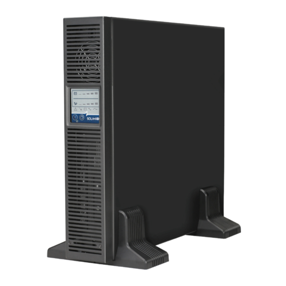
Page 10: Appearance & Components
1.3 Appearance & Components 1.3.1 Front Panel & Controls The SolaHD S4K2UC rack/tower models, in various power ratings, have the same general appearance, controls and features (see Figure 1). The various rack/tower models differ largely in the type of receptacles each has. - Page 11 3000 VA Model Input Power Plug and Cable, L5-30P Input Circuit USB Port Breaker IntelliSlot Port Output Circuit Breakers External Output Receptacles, Terminal Block Battery Cooling 5-15/20R Communication Connector Output Receptacle, L5-30R Figure 2: S4K2UC 120 V rack/tower models—rear panel components...
-
Page 12: Major Components
UPS is near ideal. Extracting this sine wave input current achieves two objectives: Efficient power use by the UPS ♦ Reduced reflected harmonics ♦ This results in cleaner power being available to other devices in the building not protected by the S4K2UC. -
Page 13: Inverter
1.4.7 Dynamic Bypass The S4K2UC provides an alternate path for utility power to the connected loads in the unlikely event of a UPS malfunc- tion. Should the S4K2UC have an overload, overtemperature or UPS failure condition, the UPS automatically transfers the connected loads to bypass. -
Page 14: Battery Mode
CAUTION Turning off the S4K2UC while in Battery Mode will result in loss of output power. If the UPS is turned off manually, it must be manually restarted after utility power returns. If the UPS is turned off by a communication signal or because the batteries are depleted, it will operate as selected in the configuration program for Auto-Restart (refer to “5.2.1 Configuration... -
Page 15: Installation
♦ Warnings, Safety Instructions booklet and WEEE recycling sheet (ISO 14001 compliance) ♦ NOTE: The S4K2UC external battery cabinet shipping package includes one battery cabinet, two spacers for tower configu- ration and one dc power cable. 2.3 Preparation for Installation 2.3.1 Installation Environment... -
Page 16: Mechanical Installation
16 | 2.0 installation 2.4 Mechanical Installation The S4K2UC may be installed as a tower or in a rack, depending on space and use considerations. The S4K2UC may be used alone, as a single UPS, or with up to four battery cabinets. - Page 17 Figure 6: Rotate the operation and display panel c. Replace the front metal bezel cover on the S4K2UC. At this point, the UPS operation and display panel and logo have been rotated 90 degrees clockwise, which provides upright viewing for users.
-
Page 18: Rack Installation
2.4.2 Rack Installation NOTES: When the S4K2UC is installed in a rack, it must be supported by a shelf, fixed rails or slide rails on each side. The ♦ factory-supplied rack mount handles cannot support the weight of the UPS. They are used to move the UPS into and out of the rack and to attach the UPS to the rack. - Page 19 S4K2UC SEriES USEr MAnUAl | 19 5. Extend the slide rail assembly by sliding the front member forward until it touches the rack’s front vertical rails (adjust- able length: 18–32 inches/457–813 mm). Use two M5 screws to fix each front member onto the front vertical rails through the installation holes.
- Page 20 20 | 2.0 installation 7. Fasten inner members (pulled from the slide rail assemblies in Step 2) to both sides of the UPS with eight M4 screws provided in this kit. Make sure that the retaining latch is near the rear of the UPS as shown in Figure 12. Inner member Retaining latch M4 screw (8 pcs)
-
Page 21: Cable Connection
11. If optional external battery cabinets are connected to the UPS, they can be placed all on one side of the UPS or stacked beneath the UPS. The installation procedures are the same as those of the UPS. NOTE: Up to four external battery cabinets can be connected to the S4K2UC. Each cabinet will increase the battery recharge time. 2.5 Cable Connection The S4K2UC rear panel has an input cable and plug, output receptacles and output cable(s). -
Page 22: Ac Input/Output Hardwire Installation
22 | 2.0 installation 1. Plug all loads into the output receptacles on the rear panel of the S4K2UC. Distribute loads evenly across all receptacles to prevent overloading individual receptacles. 2. Insert the input plug of the S4K2UC into the input power connection. - Page 23 S4K2UC SEriES USEr MAnUAl | 23 Installation procedures are as follows: 1. Remove the receptacle board on the UPS rear panel, as shown in Figure 15. Retain the six rear panel mounting screws for securing the box assembly to the UPS.
- Page 24 24 | 2.0 installation 4. Connect the input power source line, neutral and ground cables to the input line (L), neutral (N) and ground (PE) termi- nals on the UPS I/O terminal block and tighten the fixing screws (see Figures 18 and 19). 5.
-
Page 25: Connecting Battery Cables
1. Take the USB communication cables out of the accessories box. 2. Insert one end of the USB communication cable into the USB port on the rear panel of the S4K2UC (see Figure 2). 3. Insert the other end of the USB communication cable into the USB port of the computer. -
Page 26: Control & Indicators
26 | 3.0 Control & indicators 3.0 Control & indicators The operation and display panel, shown in Figure 23, is on the front panel of the S4K2UC. Battery Level indicators Load Level indicators Fault indicator Bypass indicator Ac Input indicator... -
Page 27: Standby/Manual Bypass Button
The Battery Level indicator is composed of five sets of LED bars that illuminate and flash to indicate the battery capacity level. The S4K2UC battery capacity level is shown in 20% increments (± 5%). The battery level indicators will illuminate as shown in Figure 24. -
Page 28: Load Level Indicators
28 | 3.0 Control & indicators 3.2.2 Load Level Indicators The Load Level indicator is composed of five LED bars that illuminate to indicate the relative load on the UPS output in 25% increments (± 5%). The load level indicator will illuminate as shown in Figure 25. 0 - 25% 26 - 50% 51 - 75%... -
Page 29: Operation
UPS and disconnecting the utility power from the UPS. NOTE: The S4K2UC’s battery is fully charged before delivery, but some charge will be lost during storage and shipping. To ensure that the battery has adequate reserve power to protect the connected load, charge the battery for 3 hours before putting the UPS into service. -
Page 30: Manual Bypass
4.6 Disconnecting Input Power from the S4K2UC 1. Once the UPS has been shut down as detailed in “4.5 Shut Down the S4K2UC”, disconnect the input cable plug. 2. Wait 30 seconds and verify that all indicators have turned off and the fan has stopped; this indicates that the power-off is complete. -
Page 31: Communication
S4K2UC SEriES USEr MAnUAl | 31 5.0 Communication This section describes UPS communication over the three types of communication connections on the rear of the S4K2UC: IntelliSlot port ♦ USB port (standard B-type) ♦ Terminal block communication ♦ CAUTION To maintain safety (SELV) barriers and for electromagnetic compatibility, signal cables should be segregated and run separately from all other power cables. -
Page 32: Configuration Program
5.2.1 Configuration Program Accessing the Configuration Program via USB is a new feature of the S4K2UC. For most users, the factory default settings will be adequate. This section illustrates the features available for modification, as well as the factory default settings. -
Page 33: Terminal Block Communication
WARNING When the Auto-Enable output option is selected and the UPS output is disabled using Pin 1 and Pin 2, the S4K2UC’s output can turn on automatically and without warning if the Pin 1 and Pin 2 connection is changed. -
Page 34: On Battery
♦ cannot be stopped once triggered. If utility power returns during this countdown, the S4K2UC will still shut down and must remain shut down for 10 seconds. Whether the UPS turns back on when the power is restored depends on the auto-restart setting. -
Page 35: Battery Cabinet
6.0 Battery Cabinet Optional battery cabinets are available for the S4K2UC. The battery connectors and input breaker are on the battery cabinet’s rear panel, as shown in Figure 27. For battery cabinet specifications, refer to Table 12. For battery run times, refer to Table 14. -
Page 36: Maintenance
7.1 Replacing the Internal Battery Pack The S4K2UC is designed to allow properly trained and qualified service personnel to replace the internal battery pack safely. Read the safety cautions before proceeding. Contact your SolaHD representative to obtain the part number and pricing of the appropriate replacement battery pack. -
Page 37: Battery Charging
If the S4K2UC will be stored for a long time period of time, SolaHD recommends connecting the UPS to input power for at least 24 hours every four to six months to ensure full recharge of the batteries. -
Page 38: Precautions
♦ 7.3 Precautions Although the S4K2UC has been designed and manufactured to ensure personal safety, improper use can result in electrical shock or fire. To ensure safety, observe the following precautions: Turn off and unplug the S4K2UC before cleaning it ♦... -
Page 39: Troubleshooting
Use the following information to determine whether external factors caused the problem and how to remedy the situation. 8.1 UPS Symptoms The following symptoms indicate the S4K2UC is malfunctioning: The relative indicators will illuminate, indicating the UPS detected a problem ♦... -
Page 40: Audible Alarm
40 | 8.0 troubleshooting 8.1.2 Audible Alarm An audible alarm will sound in conjunction with the visual indicators to indicate a change in UPS operating status. The audible alarm will sound as described in Table 9. Table 9: Audible Alarm Descriptions Condition Alarm Battery discharge... - Page 41 S4K2UC SEriES USEr MAnUAl | 41 Table 10: Troubleshooting Problem Cause Solution Ensure the UpS is not overloaded, ventila- tion holes are not blocked, or room ambient temperature is not excessive. Wait 30 minutes Fault and Bypass indicators and Diagnostic A UpS shutdown due to overtemperature condition to allow the UpS to cool, then restart the UpS.
-
Page 42: Specifications
42 | 9.0 Specifications 9.0 Specifications Table 11: UPS Specifications Model Parameters S4K2U700C S4K2U1000C S4K2U1500C S4K2U2000C S4K2U3000C DIMENSIONS, D x W x H, in. [mm] 23.7 x 16.9 x 3.4 Unit 19.7 x 16.9 x 3.4 [497 x 430 x 85] [602 x 430 x 85] 29.4 x 23.4 x 10.6 Shipping... - Page 43 S4K2UC SEriES USEr MAnUAl | 43 Table 11: UPS Specifications Model Parameters S4K2U700C S4K2U1000C S4K2U1500C S4K2U2000C S4K2U3000C Operating elevation Up to 10,000 ft. [3,000 m] at +40°C [+104°f] without derating Storage elevation 50,000 ft. [15,000 m] max. <43 dBA max. @ <45 dBA max.
- Page 44 44 | 9.0 Specifications Table 13: Operating Temperature Parameters Ambient temperature +25°C to +30°C [+77°f to +86°f] +30°C to +35°C [+86°f to +95°f] +35°C to +40°C [+95°f to +104°f] Maximum output power factor derating at 100% to 93% 93% to 86% 86% to 79% maximum load Table 14: Battery Backup Times...
-
Page 45: Registration & Warranty
S4K2UC SEriES USEr MAnUAl | 45 10.0 registration & Warranty 10.1 Product Registration To register your product for updates and information on service and support, visit our Web site at: http://www.solahd.com/support/registration.htm 10.2 Warranty Information Please see the enclosed “Terms & Conditions of Sale”. - Page 46 SolaHD • U.S. (800) 377-4384 • international (847) 268-6000 • www.solahd.com p/n: A272-212 rev. 1 01/29/10...
Need help?
Do you have a question about the S4K2UC and is the answer not in the manual?
Questions and answers