Table of Contents
Advertisement
Advertisement
Table of Contents

Related Manuals for Asus P8H61-MX USB3


Summary of Contents for Asus P8H61-MX USB3
- Page 1 P8H61-MX Series • P8H61-MX R2.0 • P8H61-MX USB3...
- Page 2 Product warranty or service will not be extended if: (1) the product is repaired, modified or altered, unless such repair, modification of alteration is authorized in writing by ASUS; or (2) the serial number of the product is defaced or missing.
-
Page 3: Table Of Contents
Contents Safety information ..................vi About this guide ..................vii P8H61-MX Series specifications summary ..........ix Chapter 1 Product introduction Before you proceed ..............1-1 Motherboard overview ..............1-2 1.2.1 Placement direction ............1-2 1.2.2 Screw holes ..............1-2 1.2.3 Motherboard layout ............ - Page 4 Chapter 2 BIOS information Managing and updating your BIOS ..........2-1 2.1.1 ASUS Update utility ............2-1 2.1.2 ASUS EZ Flash 2 ............2-2 2.1.3 ASUS BIOS Updater ............2-3 BIOS setup program ..............2-5 Main menu ..................2-9 2.3.1 System Language [English] ..........
- Page 5 PCI ROM Priority [Legacy ROM] ........2-26 2.7.9 Boot Option Priorities ............ 2-26 2.7.10 Boot Override ..............2-26 Tools menu ................. 2-27 2.8.1 ASUS EZ Flash Utility ........... 2-27 2.8.2 ASUS SPD Information ..........2-27 2.8.3 ASUS O.C. Profile ............2-27 Exit menu ..................2-28 Appendices Notices .......................A-1...
-
Page 6: Safety Information
Safety information Electrical safety • To prevent electric shock hazard, disconnect the power cable from the electric outlet before relocating the system. • When adding or removing devices to or from the system, ensure that the power cables for the devices are unplugged before the signal cables are connected. If possible, disconnect all power cables from the existing system before you add a device. -
Page 7: About This Guide
About this guide This user guide contains the information you need when installing and configuring the motherboard. How this guide is organized This guide contains the following parts: • Chapter 1: Product introduction This chapter describes the supported features of the motherboard. •... - Page 8 Refer to the following sources for additional information and for product and software updates. ASUS websites The ASUS website provides updated information on ASUS hardware and software products. Refer to the ASUS contact information. Optional documentation Your product package may include optional documentation, such as warranty flyers, that may have been added by your dealer.
-
Page 9: P8H61-Mx Series Specifications Summary
**DDR3 1600 MHz and higher memory frequency is supported by Intel 3rd generation processors. ® ***Refer to www.asus.com for the latest Memory QVL (Qualified Vendor List). Graphics Multi-VGA Output Support: DVI-D and D-SUB Ports DVI with Max. Resolution: 1920 x 1200 @60Hz D-SUB with Max. - Page 10 1 x 24-pin ATX power connector 1 x 4-pin ATX 12V power connector BIOS features 64 Mb Flash ROM, UEFI BIOS, PnP, DMI v2.0, WfM 2.0, ASUS EZ Flash 2, ASUS CrashFree BIOS 3, SMBIOS v2.6, ACPI v2.0a, Multi-language BIOS...
-
Page 11: Chapter 1 Product Introduction
Refer to page x for the list of included accessories. • If any of the items is damaged or missing, contact your retailer. • ASUS P8H61-MX Series motherboards include P8H61-MX R2.0 and P8H61-MX USB3 models. The layout varies between the two models. The layout illustrations in this user manual are for P8H61-MX R2.0 only. -
Page 12: Motherboard Overview
Place six screws into the holes indicated by circles to secure the motherboard to the chassis. Do not overtighten the screws! Doing so can damage the motherboard. Place this side towards the rear of the chassis P8H61-MX R2.0 ASUS P8H61-MX Series... -
Page 13: Motherboard Layout
1.2.3 Motherboard layout 18.3cm(7.2in) KB_USB56 CPU_FAN ATX12V USB34 LAN_USB12 P8H61-MX R2.0 AUDIO CHA_FAN PCIEX16 8111F Lithium Cell CMOS Power Intel ® Super 64Mb BIOS PCIEX1_1 SATA3G_3 SATA3G_1 PCIEX1_2 VT1708S SB_PWR SPEAKER USB910 USB78 SATA3G_4 SATA3G_2 AAFP F_PANEL Chapter 1: Product introduction... -
Page 14: Layout Contents
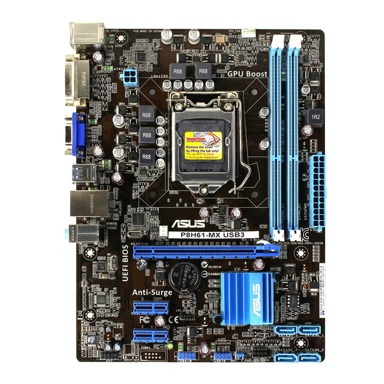
18.3cm(7.2in) KB_USB56 CPU_FAN ATX12V USB3_12 LAN_USB12 1042 P8H61-MX USB3 AUDIO CHA_FAN PCIEX16 8111F Lithium Cell CMOS Power Intel ® Super 64Mb BIOS PCIEX1_1 SATA3G_3 SATA3G_1 PCIEX1_2 VT1708S SB_PWR SPEAKER USB910 USB78 SATA3G_4 SATA3G_2 AAFP F_PANEL 1.2.4 Layout contents Connectors/Jumpers/Slots/LED Page... -
Page 15: Central Processing Unit (Cpu)
Contact your retailer immediately if the PnP cap is missing, or if you see any damage to the PnP cap/socket contacts/motherboard components. ASUS will shoulder the cost of repair only if the damage is shipment/transit-related. • Keep the cap after installing the motherboard. ASUS will process Return Merchandise Authorization (RMA) requests only if the motherboard comes with the cap on the LGA1155 socket. - Page 16 CPU notches. The CPU fits in only one correct orientation. DO NOT force the CPU into the socket to prevent bending Gold the connectors on the socket and triangle damaging the CPU! mark Alignment keys ASUS P8H61-MX Series...
- Page 17 Apply some Thermal Interface Material to the exposed area of the CPU that the heatsink will be in contact with, ensuring that it is spread in an even thin layer. Some heatsinks come with pre- applied thermal paste. If so, skip this step.
-
Page 18: Installing The Cpu Heatsink And Fan
The type of CPU heatsink and fan assembly may differ, but the installation steps and functions should remain the same. The illustration above is for reference only. ASUS P8H61-MX Series... -
Page 19: Uninstalling The Cpu Heatsink And Fan
Connect the CPU fan cable to the connector on the motherboard labeled CPU_FAN. CPU_FAN P8H61-MX R2.0 P8H61-MX Series CPU fan connector Do not forget to connect the CPU fan connector! Hardware monitoring errors can occur if you fail to plug this connector. 1.3.3 Uninstalling the CPU heatsink and fan To uninstall the CPU heatsink and fan:... -
Page 20: System Memory
DDR2 DIMM socket. DDR3 modules are developed for better performance with less power consumption. The figure illustrates the location of the DDR3 DIMM sockets: Channel Sockets Channel A DIMM_A1 Channel B DIMM_B1 P8H61-MX R2.0 P8H61-MX Series 240-pin DDR3 DIMM sockets 1-10 ASUS P8H61-MX Series... -
Page 21: Memory Configurations
• The maximum 16GB memory capacity can be supported with 8GB or above DIMMs. ASUS will update the memory QVL once the DIMMs are available in the market. • The default memory operation frequency is dependent on its Serial Presence Detect (SPD), which is the standard way of accessing information from a memory module. - Page 22 XMP 1.25V • • KINGSTON KVR1333D3N9/4G(low profile) ELPIDA J2108BCSE-DJ-F 1.5V • • KINGSTON KVR1333D3N9/4G(low profile) ELPIDA J2108BCSE-DJ-F 1.5V • • KINGSTON KVR1333D3N9/4G D2568JENCNGD9U 1.5V • • KINGSTON KVR1333D3N9/4G Hynix H5TQ2G83AFR • • (continued on the next page) 1-12 ASUS P8H61-MX Series...
- Page 23 DDR3-1333 MHz capability DIMM socket Chip support (Optional) Vendors Part No. Size Chip NO. Timing Voltage Brand KINGSTON KVR1333D3N9/4G-SP(low KINGSTON D2568JENCPGD9U 1.5V • • profile) Micron MT4JTF12864AZ-1G4D1 Micron OJD12D9LGQ • • Micron MT8JTF12864AZ-1G4F1 Micron 9FF22D9KPT • • Micron MT8JTF25664AZ-1G4D1 Micron OJD12D9LGK •...
- Page 24 · · PATRIOT PGS34G1600LLKA 4GB(2 x 2GB) DS 7-7-7-20 1.7V · · SanMax SMD-4G68HP-16KZ HYNIX H5TQ2G83BFR PBC · Silicon SP002GBLTU160V02(XMP) S-POWER 20YT5NG-1201 · Power Silicon SP004GBLTU160V02(XMP) S-POWER 20YT5NG-1201 · · Power (continued on the next page) 1-14 ASUS P8H61-MX Series...
- Page 25 DDR3-1866 MHz capability DIMM socket SS/DS Chip Chip support (optional) Vendors Part No. Size Timing Voltage Brand 1DIMM 2DIMM AX3U1866PB2G8-DP2(XMP) 8-8-8-24 1.55V-1.75V A-DATA CORSAIR CMT4GX3M2A1866C9(XMP) 4GB(2 x 2GB) 9-9-9-24 1.65V · · CORSAIR CMT6GX3MA1866C9(XMP) 6GB(3 x 2GB) 9-9-9-24 1.65V · ·...
- Page 26 • A*: Supports one module inserted into either slot as single-channel memory configuration. • B*: Supports one pair of modules inserted into both the blue slots as one pair of dual- channel memory configuration. Visit the ASUS website at www.asus.com for the latest QVL. 1-16 ASUS P8H61-MX Series...
-
Page 27: Installing A Dimm
1.4.3 Installing a DIMM Unplug the power supply before adding or removing DIMMs or other system components. Failure to do so can cause severe damage to both the motherboard and the components. Press the retaining clips outward to DIMM notch unlock a DIMM socket. -
Page 28: Expansion Slots
PCI Express x16 slot This motherboard has a PCI Express 3.0/2.0 x16 slot that supports PCI Express x16 3.0/2.0 graphic cards complying with the PCI Express specifications. PCIe 3.0 speed is supported by Intel 3rd generation processors. ® 1-18 ASUS P8H61-MX Series... -
Page 29: Jumpers
Jumpers Clear RTC RAM (3-pin CLRTC) This jumper allows you to clear the Real Time Clock (RTC) RAM in CMOS. You can clear the CMOS memory of date, time, and system setup parameters by erasing the CMOS RTC RAM data. The onboard button cell battery powers the RAM data in CMOS, which include system setup information such as system passwords. -
Page 30: Connectors
Mic In Bass/Center Bass/Center Lime (Front panel) – – – Side Speaker Out To configure an 8-channel audio output: Use a chassis with an HD audio module in the front panel to support 8-channel audio output. 1-20 ASUS P8H61-MX Series... -
Page 31: Internal Connectors
USB 2.0 ports 3 and 4 (P8H61-MX R2.0 only). These two 4-pin Universal Serial Bus (USB) ports are for USB 2.0 devices. USB 3.0 ports 1 and 2 (P8H61-MX USB3 only). These two 9-pin Universal Serial Bus (USB) ports are for USB 3.0 devices. - Page 32 The system may become unstable or may not boot up if the power is inadequate. • If you are uncertain about the minimum power supply requirement for your system, refer to the Recommended Power Supply Wattage Calculator at http://support.asus. com/PowerSupplyCalculator/PSCalculator.aspx?SLanguage=en-us for details. 1-22...
- Page 33 CPU and chassis fan connectors (4-pin CPU_FAN, 3-pin CHA_FAN) Connect the fan cables to the fan connectors on the motherboard, ensuring that the black wire of each cable matches the ground pin of the connector. CPU_FAN CHA_FAN P8H61-MX R2.0 Rotation +12V P8H61-MX Series Fan connectors Do not forget to connect the fan cables to the fan connectors.
- Page 34 Configuration > SATA Mode Selection. 7, set the SATA Mode • When using hot-plug and NCQ on Windows Vista / Windows ® ® Selection item in the BIOS to [AHCI]. See section 2.5.3 SATA Configuration for details. 1-24 ASUS P8H61-MX Series...
-
Page 35: Speaker Connector
Speaker connector (4-pin SPEAKER) The 4-pin connector is for the chassis-mounted system warning speaker. The speaker allows you to hear system beeps and warnings. SPEAKER P8H61-MX R2.0 PIN 1 P8H61-MX Series Speaker Out Connector System panel connector (10-1 pin PANEL) This connector supports several chassis-mounted functions. -
Page 36: Software Support
The contents of the Support DVD are subject to change at any time without notice. Visit the ASUS website at www.asus.com for updates. To run the Support DVD Place the Support DVD into the optical drive. -
Page 37: Chapter 2 Bios Information
BIOS in the future. Copy the original motherboard BIOS using the ASUS Update utility. 2.1.1 ASUS Update utility The ASUS Update is a utility that allows you to manage, save, and update the motherboard BIOS in a Windows environment. ®... -
Page 38: Asus Ez Flash 2
Follow the onscreen instructions to complete the update process. 2.1.2 ASUS EZ Flash 2 The ASUS EZ Flash 2 feature allows you to update the BIOS without using an OS-based utility. Before you start using this utility, download the latest BIOS file from the ASUS website at www.asus.com. -
Page 39: Asus Bios Updater
2.1.3 ASUS BIOS Updater The ASUS BIOS Updater allows you to update the BIOS in a DOS environment. This utility also allows you to copy the current BIOS file for use as a backup when the BIOS fails or gets corrupted during the updating process. -
Page 40: Updating The Bios File
Press <Tab> to switch between screen fields and use the <Up/Down/Home/End> keys to select the BIOS file and press <Enter>. BIOS Updater checks the selected BIOS file and prompts you to confirm BIOS update. Are you sure to update BIOS? ASUS P8H61-MX Series... -
Page 41: Bios Setup Program
• The BIOS setup screens shown in this section are for reference purposes only, and may not exactly match what you see on your screen. • Visit the ASUS website at www.asus.com to download the latest BIOS file for this motherboard. -
Page 42: Bios Menu Screen
• The boot device options vary depending on the devices you installed to the system. • The Boot Menu(F8) button is available only when the boot device is installed to the system. ASUS P8H61-MX Series... -
Page 43: Advanced Mode
The Advanced Mode provides advanced options for experienced end-users to configure the BIOS settings. The figure below shows an example of the Advanced Mode. Refer to the following sections for the detailed configurations. To access the EZ Mode, click Exit, then select ASUS EZ Mode. Back button Menu items... -
Page 44: Menu Items
You cannot select an item that is not user-configurable. A configurable field is highlighted when selected. To change the value of a field, select it and press <Enter> to display a list of options. ASUS P8H61-MX Series... -
Page 45: Main Menu
Main menu The Main menu screen appears when you enter the Advanced Mode of the BIOS Setup program. The Main menu provides you an overview of the basic system information, and allows you to set the system date, time, language, and security settings. 2.3.1 System Language [English] Allows you to choose the BIOS language version from the options. -
Page 46: Administrator Password
To clear the user password, follow the same steps as in changing a user password, but press <Enter> when prompted to create/confirm the password. After you clear the password, the User Password item on top of the screen shows Not Installed. 2-10 ASUS P8H61-MX Series... -
Page 47: Ai Tweaker Menu
Ai Tweaker menu The Ai Tweaker menu items allow you to configure overclocking-related items. Be cautious when changing the settings of the Ai Tweaker menu items. Incorrect field values can cause the system to malfunction. • The configuration options for this section vary depending on the CPU and DIMM model you installed on the motherboard. -
Page 48: Asus Multicore Enhancement [Enabled]
2.4.2 ASUS MultiCore Enhancement [Enabled] Allows you to set the memory frequency mode under XMP/Manual/User for maximum performance. Configuration options: [Enabled] [Disabled] 2.4.3 Memory Frequency [Auto] Allows you to set the memory operating frequency. Configuration options: [Auto] [DDR3- 800MHz] [DDR3-1066MHz] [DDR3-1333MHz] [DDR3-1600MHz] [DDR3-1866MHz] [DDR3- 2133MHz] [DDR3-2400MHz] Memory frequency options depend on installed CPU. -
Page 49: Cpu Power Management
2.4.7 CPU Power Management The sub-items in this menu allow you to set the CPU ratio and features. CPU Ratio [Auto] Allows you to manually adjust the maximum non-turbo CPU ratio. Use <+> and <-> keys or the numeric keypad to adjust the ratio. The valid value ranges vary according to your CPU model. -
Page 50: Advanced Menu
The Advanced menu items allow you to change the settings for the CPU and other system devices. Be cautious when changing the settings of the Advanced menu items. Incorrect field values can cause the system to malfunction. 2-14 ASUS P8H61-MX Series... -
Page 51: Cpu Configuration
2.5.1 CPU Configuration The items in this menu show the CPU-related information that the BIOS automatically detects. The items shown in submenu may be different due to the CPU you installed. Scroll down to display the following items: Intel Adaptive Thermal Monitor [Enabled] [Enabled] Enables the overheated CPU to throttle its clock speed to cool down. -
Page 52: Cpu Power Management Configuration
[Disabled] Disables this function. CPU C3 Report [Auto] Allows you to disable or enable the CPU C3 report to OS. CPU C6 Report [Auto] Allows you to disable or enable the CPU C6 report to OS. 2-16 ASUS P8H61-MX Series... -
Page 53: Pch Configuration
2.5.2 PCH Configuration High Precision Timer [Enabled] Allows you to enable or disable the High Precision Event Timer. Configuration options: [Enabled] [Disabled] Intel(R) Rapid Start Technology Intel(R) Rapid Start Technology [Disabled] Allows you to enable or disable the Intel(R) Rapid Start Technology.Configuration options: [Enabled] [Disabled] The following three items appear only when you set the Intel(R) Rapid Start Technology to [Enabled]. -
Page 54: Sata Configuration
SATA port. Configuration options: [Enabled] [Disabled] 2.5.4 System Agent Configuration Memory Remap Feature [Enabled] [Enabled] Allow you to enable remapping the memory above 4GB. [Disabled] Disables this function. 2-18 ASUS P8H61-MX Series... -
Page 55: Usb Configuration
Allows the system to detect the presence of USB devices at startup. If detected, the USB controller legacy mode is enabled. If no USB device is detected, the legacy USB support is disabled. Legacy USB3.0 Support [Enabled] (P8H61-MX USB3 only) [Enabled] Enables the support for USB 3.0 devices on legacy operating systems (OS). -
Page 56: Onboard Devices Configuration
[Enabled] Enables the onboard USB 3.0 controller. [Disabled] Disables the controller. Asmedia USB 3.0 Battery Charging Support [Disabled] (P8H61-MX USB3 only) This item appears only when the Asmedia USB 3.0 Controller item is set to [Enabled]. [Enabled] Enables the Asmedia USB 3.0 battery charging function. -
Page 57: Network Stack
Power On By PS/2 Keyboard [Disabled] [Disabled] Disables the Power On by a PS/2 keyboard. [Space Bar] Sets the Space Bar on the PS/2 keyboard to turn on the system. [Ctrl-Esc] Sets the Ctrl+Esc key on the PS/2 keyboard to turn on the system. [Power Key] Sets Power key on the PS/2 keyboard to turn on the system. -
Page 58: Monitor Menu
Monitor menu The Monitor menu displays the system temperature/power status, and allows you to change the fan settings. Scroll down to display the following items: 2-22 ASUS P8H61-MX Series... -
Page 59: Cpu Temperature / Mb Temperature [Xxxºc/Xxxºf]
2.6.1 CPU Temperature / MB Temperature [xxxºC/xxxºF] The onboard hardware monitor automatically detects and displays the CPU and motherboard temperatures. Select Ignore if you do not wish to display the detected temperatures. 2.6.2 CPU / Chassis Fan Speed [xxxx RPM] or [Ignore] / [N/A] The onboard hardware monitor automatically detects and displays the CPU and chassis fan speeds in rotations per minute (RPM). -
Page 60: Chassis Q-Fan Control [Enabled]
60% to 100%. When the chassis temperature is under 40ºC, the chassis fan will operate at the minimum duty cycle. 2.6.6 Anti Surge Support [Enabled] This item allows you to enable or disable the Anti Surge function. Configuration options: [Disabled] [Enabled] 2-24 ASUS P8H61-MX Series... -
Page 61: Boot Menu
[Disabled] Disables the full screen logo display feature. Set this item to [Enabled] to use the ASUS MyLogo 2™ feature. Post Report [5 sec] This item appears only when the Full Screen Logo item is set to [Disabled] and allows you to set the waiting time for the system to display the post report. -
Page 62: Option Rom Messages [Force Bios]
• To select the boot device during system startup, press <F8> when ASUS Logo appears. • To access Windows OS in Safe Mode, press <F8> after POST. -
Page 63: Tools Menu
<Enter> to display the submenu. 2.8.1 ASUS EZ Flash Utility Allows you to run ASUS EZ Flash 2. Press [Enter] to launch the ASUS EZ Flash 2 screen. For more details, see section 2.1.2 ASUS EZ Flash 2. 2.8.2... -
Page 64: Exit Menu
This option allows you to exit the Setup program without saving your changes. When you select this option or if you press <Esc>, a confirmation window appears. Select Yes to discard changes and exit. ASUS EZ Mode This option allows you to enter the EZ Mode screen. Launch EFI Shell from filesystem device This option allows you to attempt to launch the EFI Shell application (shellx64.efi) from one of... -
Page 65: Appendices
Appendices Notices Federal Communications Commission Statement This device complies with Part 15 of the FCC Rules. Operation is subject to the following two conditions: • This device may not cause harmful interference. • This device must accept any interference received including interference that may cause undesired operation. -
Page 66: Canadian Department Of Communications Statement
ASUS Recycling/Takeback Services ASUS recycling and takeback programs come from our commitment to the highest standards for protecting our environment. We believe in providing solutions for you to be able to responsibly recycle our products, batteries, other components as well as the packaging materials. Please go to http://csr.asus.com/english/Takeback.htm for the detailed recycling information in different... -
Page 67: Asus Contact Information
+1-510-739-3777 +1-510-608-4555 Web site usa.asus.com Technical Support Telephone +1-812-282-2787 Support fax +1-812-284-0883 Online support support.asus.com ASUS COMPUTER GmbH (Germany and Austria) Address Harkort Str. 21-23, D-40880 Ratingen, Germany +49-2102-959911 Web site www.asus.de Online contact www.asus.de/sales Technical Support Telephone +49-1805-010923* Support Fax... - Page 68 ASUS P8H61-MX Series...
Need help?
Do you have a question about the P8H61-MX USB3 and is the answer not in the manual?
Questions and answers