Clarke Woodworker CPT600 Operating & Maintenance Manual
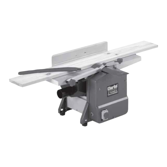
Planer/thicknesser
Hide thumbs
Also See for Woodworker CPT600:
- Operating & maintenance instructions (24 pages) ,
- Operating & maintenance instructions (18 pages) ,
- Operation & maintenance instructions manual (21 pages)

Related Manuals for Clarke Woodworker CPT600


Summary of Contents for Clarke Woodworker CPT600
- Page 1 PLANER/THICKNESSER PLANER/THICKNESSER Part No. 6460200 MODEL Nos. CPT600 and CPT800 Part No. 6462130 and 64621135 OPERATING & MAINTENANCE INSTRUCTIONS 0706...
-
Page 2: Specifications
Dimensions ............693x437x357mm ..770x449x405mm Please note that the details and specifications contained herein are correct at the time of going to print. However CLARKE International reserve the right to change specifications at any time without prior notice. Always consult the machines data bracket... -
Page 3: Table Of Contents
Please read these instructions carefully before operating the tool Thank you for purchasing this CLARKE Planer/Thicknesser designed for DIY use. Before using the device, please read this manual thoroughly and carefully follow all instructions given. This is for your own safety and that of others around you, and is also to help you achieve a long and trouble free service from your new tool. -
Page 4: Safety Precautions
General Safety Precautions WARNING: As with all machinery, there are certain hazards involved with their operation and use. Exercising respect and caution will considerably lessen the risk of personal injury. However, if normal safety precautions are overlooked or ignored, personal injury to the operator or damage to property, may result. ALWAYS Learn the machines’... -
Page 5: Additional Precautions For Planer/Thicknessers
14. ALWAYS wear proper apparel. Loose clothing or jewellery may get caught in moving parts. Wear protective hair covering to contain long hair. 15. ALWAYS use recommended accessories, the use of improper accessories could be hazardous. 16. ALWAYS remove plug from electrical outlet when adjusting, changing parts, or working on the machine. -
Page 6: Electrical Connections
ELECTRICAL CONNECTIONS Connect the mains lead to a domestic, 230 volt (50Hz) electrical supply through a fused good quality 13 amp BS 1363 plug, or a suitable fused isolator switch. WARNING: THIS APPLIANCE MUST BE EARTHED IMPORTANT: The wires in the mains lead are coloured in accordance with the following code: Green &... -
Page 7: Assembly
UNPACKING and PARTS IDENTIFICATION Carefully unpack the components and lay them out, checking against the following list. Should any part be missing or damaged in transit, please contact your Clarke dealer immediately. Fig. 1 NOTE: Dust extraction devices available from... - Page 8 Fig. 3 1. Attaching the Angle Fence The peg - ‘A’ locates in the slotted hole - ‘B’. It may be necessary to screw the peg down a little in order for the peg to locate properly. The Hex. socket head screw with washers (in the bag of loose parts), is used to secure the fence to the table, through slot ‘C’, into threaded hole ‘D’.
-
Page 9: Operation
OPERATION A. Planing ENSURE the timber is completely free of nails, screws and staples etc., before use. 1. Set the depth of cut, using the Depth of Cut Setting Knob - see Fig.1. Turn anticlockwise to increase the cutting depth, clockwise to decrease, using the scale, indicated in Fig. -
Page 10: Maintenance
Cutter blades will require sharpening or replacing. Care should be taken at all times when handling them, they are very sharp, even when appearing to be dull. Blades must always be fitted as a pair, and must be of the same type, only fit blades recommended by the Clarke International. - Page 11 First, ensure the machine is switched OFF and isolated from the mains supply. 1. Turn the cutter height adjuster so that it registers zero. i.e turn the knob clockwise so that the depth of cut, registered on the scale, is zero. 1.
-
Page 12: Parts Diagrams
SPARE PARTS DIAGRAM - CPT600... -
Page 13: Parts List
PARTS LIST No. Description Qty Part No. No. Description Qty Part No. Cable Clamp NXCPT6042 Bolt NXCPT6001 Cord Stowage Bkt NXCPT6002 Rubber Buffer NXCPT6043 Side Cover NXCPT6003 Flat Belt NXCPT6044 Bolt NXCPT6004 Washer NXCPT6045 Locking Washer NXCPT6005 Locking Washer NXCPT6046 Rubber Foot NXCPT6006 Bolt... - Page 14 No. Description Qty Part No. No. Description Qty Part No. Bolt NXCPT6078 Stud Bolt NXCPT6125 Locking Washer NXCPT6079 Cover NXCPT6126 Washer NXCPT6080 Square Tube NXCPT6127 Chain Wheel NXCPT608/1 127A Cover NXCPT6127A Chain NXCPT6082 Washer NXCPT6128 Belt Disk NXCPT6083 128A Locking Ring NXCPT6128A Bolt NXCPT6084...
- Page 15 SPARE PARTS DIAGRAM - CPT800...
- Page 16 PARTS LIST - CPT800 No. Description Qty Part No. No. Description Qty Part No. Bolt NXCPT8001 Cable Clamp NXCPT8042 Cord Stowage Bkt NXCPT8002 Rubber Buffer NXCPT8043 Side Plate Top NXCPT8003 Flat Belt NXCPT8044 Bolt NXCPT8004 Washer NXCPT8045 Locking Washer NXCPT8005 Locking Washer NXCPT8046 Rubber Buffer...
- Page 17 No. Description Qty Part No. No. Description Qty Part No. Locking Washer NXCPT8079 Cover NXCPT8126 Washer NXCPT8080 Square Tube NXCPT8127 Chain Wheel NXCPT8081 127A Cover NXCPT8127A Chain NXCPT8082 Washer NXCPT8128 128A Locking Ring NXCPT8128A Belt Disk NXCPT8083 128B Locking Ring NXCPT8128B Bolt NXCPT8084...
-
Page 18: Parts And Service Contacts
IMPORTANT: The use of parts other than CLARKE replacement parts may result in safety hazards, decreased tool performance and may invalidate your warranty. PARTS & SERVICE CONTACTS For Spare Parts and Service, please contact your nearest dealer, or CLARKE International, on one of the following numbers.
Need help?
Do you have a question about the Woodworker CPT600 and is the answer not in the manual?
Questions and answers