
Related Manuals for Clarke CEP720B


Summary of Contents for Clarke CEP720B
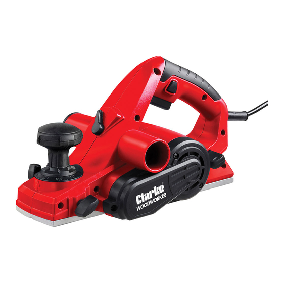
- Page 1 82MM ELECTRIC PLANER MODEL NO: CEP720B PART NO: 6462019 OPERATION & MAINTENANCE INSTRUCTIONS DL0621 - ISS 1 ORIGINAL INSTRUCTIONS...
-
Page 2: Environmental Recycling Policy
INTRODUCTION Thank you for selecting this Clarke 82mm Electric Planer. The electric planer is intended for removing surface material with a rotating blade that is parallel to the base plate. Before using the device, please read this manual thoroughly and carefully follow all instructions given. -
Page 3: General Power Tool Safety Warnings
GENERAL POWER TOOL SAFETY WARNINGS WARNING: READ ALL SAFETY WARNINGS AND ALL INSTRUCTIONS. FAILURE TO FOLLOW THE WARNINGS AND INSTRUCTIONS CAN RESULT IN ELECTRIC SHOCK, FIRE AND/OR INJURY. Save all warnings and instructions for future reference. The term “power tool” in the warnings refers to your mains-operated electric planer. -
Page 4: Personal Safety
PERSONAL SAFETY 1. Stay alert, watch what you are doing and use common sense when operating a power tool. DO NOT use a power tool while you are tired or under the influence of drugs, alcohol or medication. A moment of inattention while operating power tools can result in personal injury. -
Page 5: Planer Safety Warnings
operation. If damaged, have the power tool repaired before use. Many accidents are caused by poorly maintained power tools. 6. Use the power tool, accessories and tool bits etc. in accordance with these instructions, taking into account the working conditions and the work to be performed. -
Page 6: Safety Symbols
10. DO NOT put your fingers or any objects into the shavings exhaust port or clean out shavings while the tool is running. Contact with blade will cause injury. 11. Remove the plug from the power source if it becomes necessary to remove woodchips. -
Page 7: Electrical Connections
ELECTRICAL CONNECTIONS WARNING: READ THESE ELECTRICAL SAFETY INSTRUCTIONS FULLY BEFORE CONNECTING THE TOOL TO THE MAINS SUPPLY. This tool is provided with a standard 13 amp, 230 volt (50Hz), BS 1363 plug, for connection to a standard, domestic electrical supply. If the plug need changing, make sure that a plug of identical specification is used. - Page 8 OVERVIEW Parts & Service: 020 8988 7400 / E-mail: Parts@clarkeinternational.com or Service@clarkeinternational.com...
-
Page 9: Operation
OPERATION USING THE SAFETY KICKSTAND The safety kickstand on the rear of the planer swings down to help keep the blade from touching the workbench when the planer is not being used. The kickstand is designed to swing up and out of the way when the back of the planer crosses the leading edge of the workpiece. -
Page 10: Switching On/Off
SWITCHING ON/OFF The planer has a trigger lock to prevent accidental start-ups. 1. To turn the planer on, push the trigger lock and then squeeze the trigger switch. 2. To switch off, release the trigger switch. CAUTION: ALWAYS ENSURE THAT THE NUMBER ON THE DEPTH GAUGE IS AT THE “0”... -
Page 11: Grain Direction
GRAIN DIRECTION WARNING: DO NOT PLANE ACROSS THE GRAIN OF THE WOOD. DO NOT PLANE END GRAIN AS THE WOOD WILL SPLINTER. The planer must always cut in the same direction as the grain of the wood. There are six sides to every board: two face grains, two side/edge grains, and two end grains. -
Page 12: Using The Planer
USING THE PLANER WARNING: WEAR SAFETY GOGGLES AT ALL TIMES. USE EAR PROTECTION SUCH AS PLUGS OR EAR DEFENDERS DURING EXTENDED PERIODS OF OPERATION. WEAR A DUST MASK. 1. Secure the workpiece to a stable platform. 2. Hold the planer firmly with both hands. -
Page 13: Making A Chamfer
MAKING A CHAMFER The V-groove in the front shoe allows you to create a sloping edge along the corner of your workpiece. 1. Make sure that the workpiece is secured to a stable platform. 2. Align the V-groove in the front shoe of the planer with the corner edge of the workpiece. -
Page 14: Using The Parallel Guide Fence
USING THE PARALLEL GUIDE FENCE The parallel guide fence ensures that the planer travels parallel to the edge of the wood, providing a straight cut at your desired cutting width. This feature is helpful for planing door edges, wood trim and boards. To attach the parallel guide fence: 1. -
Page 15: Using The Rabbeting Depth Guide
USING THE RABBETING DEPTH GUIDE The rabbeting depth guide can be adjusted anywhere from 0 to 18mm above the base of the planer. To attach the rabbeting depth guide: 1. Disconnect the planer from the power source. 2. Attach the rabbeting depth gauge to the right-hand side of the planer using the lock knob. -
Page 16: Removing Or Installing Planer Blades
REMOVING OR INSTALLING PLANER BLADES WARNING: PLANER BLADES ARE SHARP AND FRAGILE. WEAR PROTECTIVE GLOVES TO PROTECT YOUR HANDS. HANDLE THE BLADES CAREFULLY TO AVOID PERSONAL INJURY OR DAMAGE TO THE BLADES. WARNING: DO NOT ATTEMPT TO SHARPEN OR USE RESHARPENED BLADES. The condition of the blades will affect the precision of the cuts. - Page 17 4. Hold the blade drum in place and carefully slide out the blade. • You can also use a wooden block to push the blade out of the blade drum. 5. Clean out all foreign matter adhering to the blade drum and the blade using a brush or compressed air, making sure eye protection is worn.
-
Page 18: Maintenance And Servicing
WARNING: MAKE SURE THAT THE PLANER IS TURNED OFF AND UNPLUGGED FROM THE POWER SOURCE BEFORE CLEANING AND MAINTENANCE OPERATIONS. WARNING: REFER TO YOUR CLARKE DEALER IF INTERNAL MAINTENANCE IS NECESSARY. CLEANING • Keep the planer clean of any wood chips, dust, dirt or debris. -
Page 19: Carbon Brushes
CARBON BRUSHES To maintain maximum efficiency of the motor, we recommend changing the carbon brushes every 60 hours of operation. To inspect or replace the carbon brushes: 1. Unscrew and remove the motor cover on the right. 2. Carefully take out the two carbon brushes using pliers and replace with new brushes. -
Page 20: Drive Belt
1. Unscrew and remove the belt cover on the left. 2. Replace with an identical replacement belt and replace the drive belt cover. SPECIFICATIONS Model CEP720B Voltage 230V~ 50Hz Rated Input Power 720W Maximum Depth of Cut 3 mm Planing Width (Width of Cut) -
Page 21: Other Tools In The Current Clarke Range
OTHER TOOLS IN THE CURRENT CLARKE RANGE Replacement Blades- Palm Sander - CPS125 Power File - CPF13 CEP720RB •Length: 80mm •Powerful 125W motor •400w, 230v motor •Depth: 5.5mm •No load speed: •Variable speed: 300 - 13500rpm 1700 m/min •Thickness: 1.2mm •Part No. - Page 22 DECLARATION OF CONFORMITY - UKCA Parts & Service: 020 8988 7400 / E-mail: Parts@clarkeinternational.com or Service@clarkeinternational.com...
-
Page 23: Declaration Of Conformity (Ce)
DECLARATION OF CONFORMITY - CE Parts & Service: 020 8988 7400 / E-mail: Parts@clarkeinternational.com or Service@clarkeinternational.com...
Need help?
Do you have a question about the CEP720B and is the answer not in the manual?
Questions and answers