Clarke CPT600 Operation & Maintenance Instructions Manual
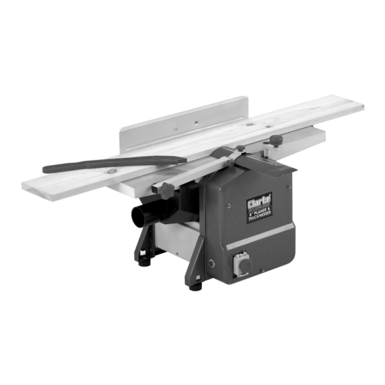
Planer/thicknesser
Hide thumbs
Also See for CPT600:
- Operating & maintenance manual (18 pages) ,
- Operating & maintenance instructions (24 pages) ,
- Operating & maintenance instructions (18 pages)

Related Manuals for Clarke CPT600


Summary of Contents for Clarke CPT600
- Page 1 PLANER/THICKNESSER MODEL NO: CPT600 PART NO: 6462130 OPERATION & MAINTENANCE INSTRUCTIONS GC0321 rev 1 ORIGINAL INSTRUCTIONS...
-
Page 2: Specifications
INTRODUCTION Thank you for purchasing this CLARKE Planer/Thicknesser designed for DIY use. Before using the machine, please read this manual thoroughly and carefully follow all instructions given. This is for your own safety and that of others around you and is also to help you achieve a long and trouble free service from your new machine. -
Page 3: Safety Warnings
SAFETY WARNINGS WARNING: READ ALL SAFETY WARNINGS AND ALL INSTRUCTIONS. FAILURE TO FOLLOW THE WARNINGS AND INSTRUCTIONS CAN RESULT IN ELECTRIC SHOCK, FIRE AND/OR INJURY. Save all warnings and instructions for future reference. The term “power tool” in the warnings refers to your mains-operated electric planer. -
Page 4: Personal Safety
PERSONAL SAFETY 1. Stay alert, watch what you are doing and use common sense when operating a power tool. Do not use a power tool while you are tired or under the influence of drugs, alcohol or medication. A moment of inattention while operating power tools can result in personal injury. -
Page 5: Planer Safety Warnings
6. Keep cutting tools sharp and clean. Sharp cutting edges are less likely to bind and are easier to control. 7. Use the power tool, accessories and tool bits etc. in accordance with these instructions, taking into account the working conditions and the work to be performed. -
Page 6: Electrical Connections
ELECTRICAL CONNECTIONS WARNING: READ THESE ELECTRICAL SAFETY INSTRUCTIONS FULLY BEFORE CONNECTING THE TOOL TO THE MAINS SUPPLY. This product is provided with a standard 13 amp, 230 volt (50Hz), BS 1363 plug, for connection to a standard, domestic electrical supply. If the plug needs changing, make sure that a plug of identical specification is used. -
Page 7: Unpacking And Parts Identification
UNPACKING AND PARTS IDENTIFICATION Carefully unpack the components and lay them out, checking against the following list. Should any part be missing or damaged in transit, please contact your Clarke dealer immediately. CONTENTS • 1 x Planer/Thicknesser • 1 x Side Fence •... -
Page 8: Assembly And Installation
ASSEMBLY AND INSTALLATION Ensure the planer is located where there is adequate light and a suitable power supply. If cable a extension is used, ensure it does not trail along the workshop floor as this could be extremely hazardous. There must be sufficient room for the workpiece to move through its entire length. - Page 9 ATTACHING THE TABLE ADJUSTMENT HANDLE Slide the table adjustment handle (16) onto the shaft (see Fig. 4). To raise or lower the table. Adjust the thicknesser table by turning the table adjustment handle: Lower the table - Turn anticlockwise. Raise the table - Turn clockwise. ATTACH THE DUST/CHIP EXTRACTION CHUTE IMPORTANT: Please note that the Dust Chute MUST ALWAYS be in place;...
-
Page 10: Operation
B. FOR THICKNESSING B.1 Remove the Angle Fence. B.2 Push the Cutter Guard out of its holder so that the Chute may be attached to the table, as shown in Fig.7. Ensure both locking keys are pushed firmly into the slots in the table, shown in Fig.6. - Page 11 6. Applying firm downwards pressure and keeping the workpiece against the fence, proceed to feed the work over the cutter. Do not feed too quickly. IMPORTANT: When coming to the end of a piece, ALWAYS use the push stick to finish - see Fig.8. This is an important safety point. 7.
-
Page 12: Reset Button
Blades must always be fitted as a pair and must be of the same type. Only fit blades recommended by the Clarke International. Parts & Service: 020 8988 7400 / E-mail: Parts@clarkeinternational.com or Service@clarkeinternational.com... - Page 13 First, ensure the machine is switched OFF and isolated from the mains supply. 1. Turn the cutter height adjuster so that it registers zero. i.e. turn the knob clockwise so that the depth of cut, registered on the scale, is zero. 2.
-
Page 14: Drive Belt Replacement
DRIVE BELT REPLACEMENT 1. Remove the front cover - 3 nuts. 2. Remove the worn or broken drive belt. 3. Place the replacement drive belt over the small belt wheel. 4. Position part of the drive belt over the large belt wheel as shown in fig 13. -
Page 15: Declaration Of Conformity
DECLARATION OF CONFORMITY Parts & Service: 020 8988 7400 / E-mail: Parts@clarkeinternational.com or Service@clarkeinternational.com... - Page 16 CPT600 COMPONENT PARTS Parts & Service: 020 8988 7400 / E-mail: Parts@clarkeinternational.com or Service@clarkeinternational.com...
- Page 17 CPT600 COMPONENT PARTS Description Description Bolt Sleeve Cable stowage bracket Bolt Side cover Side plate (left) Bolt Cutting depth scale Locking washer Bolt Rubber foot Locking washer Washer Motor cover Washer Bolt Locking washer Locking washer Bolt Washer Rod (long)
- Page 18 Description Description Thermo-protector Bearing cover Bolt Locking washer Bolt Bolt Terminal Washer Switch Bolt Outfeed roller Locking ring Infeed roller Washer Retracting spring Chain wheel Bearing bush Square sleeve Gear wheel Washer Locking ring Ratchet Belt wheel Bolt Lantern ring Clamping device Needle bearing Cutting blade...
- Page 19 Description Description Stud bolt Cover Bolt Square tube 127A Cover Bolt Washer Hand knob 128A Locking ring Angle piece 128B Locking ring Stalk-long Hand Knob Guide fence Bolt Clamp plate Limit Switch Washer Switch cover Locking washer 132A Washer Bolt 132B Bolt Dust collector...
Need help?
Do you have a question about the CPT600 and is the answer not in the manual?
Questions and answers