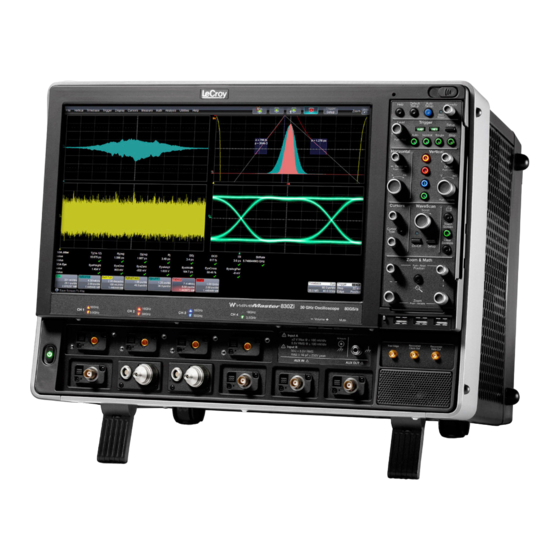
Getting Started M anual WaveM aster 8Zi and Zi-A Oscilloscopes...
Page 2
WaveMaster 8 Zi and Zi-A Oscilloscopes October, 2010...
Page 3
LeCroy shall not be responsible for any defect, damage, or failure caused by any of the following: a) attempted repairs or installations by personnel other than LeCroy representatives or b) improper connection to incompatible equipment, or c) for any damage or malfunction caused by the use of non-LeCroy supplies.
Getting Started Manual TABLE OF CONTENTS Welcome ..............12 Contact LeCroy for Support ........12 Thank You ..............13 Safety Requirements ..........13 Safety Symbols ............13 Operating Environment ..........15 Safety Certification ........... 16 Cooling ..............17 AC Power Source............17 Power Consumption ..........
Page 5
WaveMaster 8 Zi – Zi-A Oscilloscopes Vertical Front Panel Controls ........34 Cursors Front Panel Controls ........35 WaveScan Front Panel Controls ....... 36 General Controls Front Panel Controls ....36 Zoom and Math Front Panel Controls ...... 37 Connecting ..............38 Probe Interfaces ............
Page 7
WaveMaster 8 Zi – Zi-A Oscilloscopes Using Find Scale ............79 Variable Gain ............79 Enabling Variable Gain ..........79 Channel Deskew ............80 Channel Deskew Setup ..........80 Response Optimization Modes ........ 80 Trigger ............... 82 Trigger Overview ............82 Trigger Types ............
Page 8
Getting Started Manual Display Setup ............98 Moving Traces from Grid to Grid ......100 XY Display ..............101 Display Grids ............101 Zooming Waveforms ..........102 Zooming a Single Channel ........103 Touch-and-Drag Zooming ........105 Quickly Zooming Multiple Waveforms ....106 Persistence ..............
Page 9
WaveMaster 8 Zi – Zi-A Oscilloscopes Parameter Analysis ..........134 Pass/Fail Testing ............. 136 Customization ............143 Customization Overview ........143 Documenting Your Work Using LabNotebook .... 145 Introduction to LabNotebook ........ 145 Creating a Notebook Entry ........146 Saving and Recalling Setups ........151 Saving Oscilloscope Setup(s) ........
Page 10
Getting Started Manual Clipboard ..............165 File ................167 E-mail ..............168 Auxiliary Output Signals .......... 170 Auxiliary Output Setup..........170 Date and Time ............171 Setting the Date and Time Manually ...... 171 Setting the Date and Time from the Internet ..171 Setting the Date and Time from Windows .....
Page 11
WaveMaster 8 Zi and Zi-A Specifications ....179 CERTIFICATIONS ............. 179 CE Declaration of Conformity ......... 179 EMC Directive ............179 Low-Voltage Directive ..........180 UL and cUL .............. 181 Contact LeCroy for Support ........181 ® Windows License Agreement ....... 194 Index ................ 195 918893 RevA...
When your WaveMaster 8 Zi and Zi-A Series Oscilloscope is delivered, verify that all items on the packing list or invoice copy have been shipped to you. Contact your nearest LeCroy customer service center or national distributor if anything is missing or damaged. If you do not contact us immediately, we cannot be responsible for replacement.
WaveMaster 8 Zi – Zi-A Oscilloscopes Thank You We truly hope these materials provide increased comprehension when using LeCroy's fine products. Sincerely, David C. Graef LeCroy Corporation Vice President and Chief Technology Officer Safety Requirements This section contains information and warnings that must be observed to keep the instrument operating in a correct and safe condition.
Page 14
Getting Started Manual This symbol is used to denote the measurement ground connection. This symbol is used to denote a safety ground connection. On (Supply). This is the AC mains connect/disconnect switch at the back of the instrument. Off (Supply). This is the AC mains connect/disconnect switch at the back of the instrument.
WaveMaster 8 Zi – Zi-A Oscilloscopes CAUTION The CAUTION sign indicates a potential hazard. It calls attention to a procedure, practice or condition which, if not followed, could possibly cause damage to equipment. If a CAUTION is indicated, do not proceed until its conditions are fully understood and met.
Getting Started Manual WARNING The oscilloscope must not be operated in explosive, dusty, or wet atmospheres. CAUTION Protect the oscilloscope’s display touch screen from excessive impacts with foreign objects. CAUTION Do not exceed the maximum specified front panel terminal (CH1, CH2, CH3, CH4, AUX IN, and AUX OUT) voltage levels.
WaveMaster 8 Zi – Zi-A Oscilloscopes Pollution Degree 2 refers to an operating environment where normally only dry non-conductive pollution occurs. Conductivity caused by temporary condensation should be expected. Protection Class 1 refers to grounded equipment, in which protection against electric shock is achieved by Basic Insulation and by means of a connection to the protective ground conductor in the building wiring.
Getting Started Manual No manual voltage selection is required because the instrument automatically adapts to line voltage. Power Consumption </= 975 watts (975 VA) for 4 - 16 GHz 8 Zi series models and for 4 – 20 GHz 8 Zi-A series models. </= 1025 watts (1025 VA) for 20 - 30 GHz 8 Zi series models and 25 –...
Page 19
WaveMaster 8 Zi – Zi-A Oscilloscopes Standby (Power) Switch and Oscilloscope Operational States The front Standby (Power) switch controls the operational state of the oscilloscope. This toggle switch is activated by momentarily pressing and releasing it. The color of the LED below the switch indicates the status of the oscilloscope as follows: ...
Getting Started Manual The oscilloscope can always be placed in the Standby state (LED Off) – Power Off (except for some housekeeping circuits) by pressing and holding in the Standby toggle switch for approximately 5 seconds. CAUTION Hibernate mode is not supported by the Power button. Therefore, Windows®...
Page 21
WaveMaster 8 Zi – Zi-A Oscilloscopes Proper use of the instrument depends on careful reading of all instructions and labels. WARNING Any use of the oscilloscope in a manner not specified by the manufacturer may impair the instrument’s safety protection. 918893 RevA...
Getting Started Manual Hardware Front Panel Numbered labels on this image correspond with descriptions on the following table. Number and Description 1. Power 5. Volume Control 9. USB Ports Button and Mute Button 10. Detachable Front 2. Channel Row 6. Ground Panel-Remote LED Indicator Connector...
WaveMaster 8 Zi – Zi-A Oscilloscopes Detaching and Attaching the Front Panel Detach the front panel from the oscilloscope by sliding the detachment lever to the left and pulling at the right. Attach the front panel by inserting the lower part first, sliding the detachment lever to the left, and then pushing the top in place.
Page 24
USB - A to USB - Mini B cable provided. Note: While a standard front panel comes with your Zi oscilloscope, LeCroy offers additional standard front panels or a 4 channel version (as follows) to better suit the way you work. Contact your local Contact LeCroy for Support for more details on front panels (additional standard and 4 channel versions).
WaveMaster 8 Zi – Zi-A Oscilloscopes I/O Panel The I/O Panel is located on the rear of the instrument as follows: 918893 RevA...
Page 26
Numbered labels on this image of the I/O Panel correspond with descriptions on the following table. The exact location does vary on WavePro 7 Zi, WaveMaster 8 Zi and Zi-A instruments. Number and Description 1. LBUS (LeCroy 5. External VGA 10. PCI Expansion Slots Bus)
WaveMaster 8 Zi – Zi-A Oscilloscopes Back Panel Numbered labels on this image correspond with descriptions on the following table. Number and Description 1. External Clock 2. External Clock 4. DVD-CD + R Input (Grounded Output Drive EMI Shield 3. Removable Hard 5.
Page 28
Getting Started Manual 1. Plug your external display (ZI-EXTDISP-15 option) power cord into an AC socket and the DVI plug into the PCI slot. Connect your USB plug (where applicable) to an available port. Note: A standard VGA monitor can be used by connecting it directly to the VGA Port.
Page 29
WaveMaster 8 Zi – Zi-A Oscilloscopes The following picture shows a WavePro 7 Zi with the LeCroy external display attached (optional ZI-EXTDISP-15). 918893 RevA...
Getting Started Manual Basic Controls Hardware and Software Controls The following Basic Control topics cover the general usage of the hardware buttons located on the oscilloscope's front panel and the screen control interface elements of the software. Front Panel Controls Note: Many front panel controls directly correspond with screen layout controls.
Miscellaneous Setup Controls Help - Press to open the LeCroy Online Assistant where you can click to open the oscilloscope online help table of contents, index, or search for a topic using a keyword. If the second monitor is installed, the online help opens on the second monitor.
Getting Started Manual If Auto Setup is run when no channels are turned on, all channels are affected. When more than one channel is turned on, the first channel with a signal applied to it is automatically set up for edge triggering.
WaveMaster 8 Zi – Zi-A Oscilloscopes Single - Press to turn on Single Trigger mode, which arms the oscilloscope to trigger once (single-shot acquisition) when the input signal meets the trigger conditions set for the type of trigger selected. If the scope is already armed, it will force a trigger. ...
Getting Started Manual Vertical Front Panel Controls Note: Vertical front panel controls correspond with screen menu selection: Vertical → Channel Setup. Channels - The channel buttons control both channel ON/OFF and which channel is active for the Vertical Offset and Volts/Div knobs controls.
WaveMaster 8 Zi – Zi-A Oscilloscopes Cursors Front Panel Controls Note: Cursors front panel controls correspond with screen menu selection: Cursors → Cursors Setup. Absolute Cursor - Press to set the cursor position to the default 25% position, either horizontal or vertical (depending on which cursor type you are using).
Getting Started Manual WaveScan Front Panel Controls Note: WaveScan front panel controls correspond with screen menu selection: Analysis → WaveScan. Scroll - If WaveScan is ON, turn to scroll through the table of WaveScan-filtered events. If WaveScan is OFF, turn to adjust the selected data entry field.
WaveMaster 8 Zi – Zi-A Oscilloscopes Press the Save Screen to Clipboard button on the flyout menu to save the current screen image to the clipboard. Press the Send Screen to Email button to send the current screen image using the email settings on the Utilities → Utilities Setup → Hardcopy dialog.
Connecting Probe Interfaces LeCroy Zi Series oscilloscopes contain probe interfaces that provide a complete measurement solution from probe tip to oscilloscope display. All probe interfaces permit automatic recognition of connected probes. For active single-ended and differential voltage probes and current probes,...
Page 39
WaveMaster 8 Zi – Zi-A Oscilloscopes The LeCroy 8 Zi series oscilloscopes with bandwidths of 4 to 16 GHz and 8 Zi-A series with bandwidths of 4 to 20 GHz include both ProBus and ProLink probe interfaces. Figure 4-1. A LeCroy Zi series oscilloscope showing the four sets of ProBus/ProLink probe interfaces.
Page 40
Getting Started Manual rings for detecting passive probes. This is a feature unique to LeCroy in the 4 - 45 GHz bandwidth range. WaveMaster 8 Zi uses 2.92 mm inputs for the 20 - 30 GHz signal inputs and WaveMaster 8 Zi-A uses 2.92 mm inputs for the 25 - 30 GHz signal inputs.
Page 41
Note: Input A (Upper) and B (Lower) refer to the two rows of input channels specifically available on LeCroy 8 Zi series 4 - 16 GHz oscilloscopes and LeCroy 8 Zi-A series 4 - 20 GHz oscilloscopes. The setup for the ProBus interface is shown in the following figure. This interface also allows the selection of input impedance, 50 Ω/1 MΩ.
Page 42
Getting Started Manual Another universal probe interface advantage is the ability to switch between two probe setups. This function is remotely programmable allowing the interface to operate like a switch. The ability to select four out of eight inputs provides unheard of connection flexibility and eliminates the need for costly, easy-to-lose adapters.
WaveMaster 8 Zi – Zi-A Oscilloscopes ProLink Interface Adapters For some instruments, LeCroy's ProLink Adapters (LPA) provides the ability to connect your signal in the following ways: Using a BMA connector. SMA, using the BMA-to-SMA adapter (4 are sent standard on 4 - 8 GHz units).
Getting Started Manual Connecting the Adapters The mating end of the ProLink adapter has four fastening clips (shown right). When installing an adapter on the instrument's connector panel, align the male 6-pin connector with the female connector and push the adapter straight in. There will be some resistance and you'll hear clicks as the four clips slide into place.
WaveMaster 8 Zi – Zi-A Oscilloscopes DC Level - This is a reference level. Trigger Enabled - This function can be used as a gating function to trigger another instrument when the oscilloscope is ready. Pass/Fail - Allows you to set a pulse duration from 1 µs to 131 ms; generates a pulse when pass/fail testing is active and conditions are met.
Getting Started Manual Probes LeCroy offers a variety of passive and active probes for use with your X- Stream oscilloscope. Visit www.lecroy.com for specifications and ordering information. Current Probes - Current Probes measure the current passing through a wire; current probes do not use the traditional probing style of placing a tip onto a test point.
WaveMaster 8 Zi – Zi-A Oscilloscopes Passive Probe Compensation Passive probes must be compensated to flatten overshoot. This is accomplished by means of a trimmer at the connector end of the probe. 1. Attach the connector end of your passive probe to any channel. 2.
Getting Started Manual Display Dashboard Screen Layout, Groupings, and Controls The instrument's screen is divided into five main sections: Menu Bar Signal Display Grid Descriptor Labels Dialog(s) The Message Bar Note: Many front panel controls directly correspond with screen layout controls.
WaveMaster 8 Zi – Zi-A Oscilloscopes Specific Menu Bar functions are referenced using arrow-separated path descriptions. For example, the Save Setup function is referenced as File → Save Setup. PLEASE NOTE THE FOLLOWING: For common oscilloscope operations, you don’t need to use the top menu bar (since you can access most dialogs from the Front Panel or from the Descriptor Labels).
Getting Started Manual An Undo button is often available to the right of the Quick Access Toolbar on the Menu Bar. The Signal Display Grid The grid area is divided into 8 vertical divisions and 10 horizontal divisions just like any other oscilloscope. Set up the signal display area by touching Display →...
Page 51
WaveMaster 8 Zi – Zi-A Oscilloscopes All trigger delay values (including post-trigger delay, shown here) are displayed in the Timebase Descriptor Label. Zero delay is the horizontal center of the oscilloscope display. The default setting (Time) is for delay readout (in seconds) and to move proportionately when the timebase knob is turned.
Getting Started Manual Signal Display Grid Pop-Up Menu On the Signal Display Grid, the Pop-up menu provides assistance while using the oscilloscope. Clicking on a waveform opens a pop-up menu. From this pop-up menu, you can perform the following functions: ...
Page 53
WaveMaster 8 Zi – Zi-A Oscilloscopes These indicators have a long and short form, respectively. Figure 4-7. The long and short forms of trace descriptor indicators. Besides channel traces, math and parameter measurement labels are also displayed. Labels are displayed only for traces that are turned on. Vertical and horizontal trace descriptor (labels) are displayed below the grid.
Getting Started Manual Display Pop-Up Menu You can click on a trace descriptor label to open a pop-up menu. From this pop-up menu, you can perform the following functions: Open the Setup dialog for the trace. Open the Math dialog for the trace. ...
Page 55
WaveMaster 8 Zi – Zi-A Oscilloscopes A dialog box opens in which to create the label. If you are creating a label for the first time for this waveform, Label1 is displayed as default text when the Add label button is clicked. From this pop-up you can edit existing annotations, change the label placement on the waveform, add labels, remove labels, and toggle the visibility.
Getting Started Manual If you want to change the label's text, touch inside the Label Text field. A pop-up keyboard appears for you to enter your text. Touch O.K. on the keyboard when you are done. The edited text automatically appears in the label on the waveform.
WaveMaster 8 Zi – Zi-A Oscilloscopes Tool Bar Buttons Several dialogs contain common functions accessible from a row of buttons that can save you a step or two when using a particular function (instead of accessing the respective location from the menu bar). For example, at the bottom of the Channel Setup dialog, these buttons (sometimes labeled as Actions) perform the following functions: ...
Getting Started Manual Another example is seen in the buttons appearing at the bottom of the Measure Px dialogs. The button may be selected in order to display the functions named on the buttons (sometimes labeled as Actions): Using these buttons allow you to remain in the Measure dialog while setting up a Math trace on a parameter measurement.
WaveMaster 8 Zi – Zi-A Oscilloscopes Whenever you turn on a channel, math, or memory trace using either the menu bar or trace descriptor label, the dialog at the bottom of the screen automatically switches to the vertical setup or math setup dialog for that selection.
Digital Bandwidth Interleave is a method for combining channels to double bandwidth - just as oscilloscope manufacturers have for years interleaved channels to double sample rate and memory lengths. LeCroy’s 8 Zi-A series makes use of 6th generation DBI technology providing the highest possible performance.
Page 61
WaveMaster 8 Zi – Zi-A Oscilloscopes When these buttons are selected, the channel pair (C1/C2, C3/C4 on 25 and 30 GHz models) or channel (C1/C2/C3/C4 combined for 45 GHz model) is dedicated to that specific level of bandwidth throughput. However, if the lower buttons are selected each channel (1 - 4) is ≤...
Page 62
Getting Started Manual The Vertical Scale B Scale V/div (Timebase) value is automatically set to 50 mV/div. If you set this to a different value and deactivate DBI, the system retains the last one used when DBI is reactivated. ...
Page 63
WaveMaster 8 Zi – Zi-A Oscilloscopes Using the External Interleaving Device on 4 - 20 GHz WaveMaster 8 Zi-A Units Combine your channels by using the External Interleaving Device over the C1/C2 and C3/C4 pairs. When this is done, your C2 and C3 traces are sampled at 80 GS/s.
Getting Started Manual The External Interleaving Device tab on the display dialog shows some attributes. Figure 4-9. C2 Interleaved Signal Attributes Channels C1 (and C4 if second pair is used) are shown as not active, and also has the External Interleaving Device attributes on corresponding display dialogs.
WaveMaster 8 Zi – Zi-A Oscilloscopes Single-shot Sampling Mode Basic Capture Technique A single-shot acquisition is a series of digitized voltage values sampled on the input signal at a uniform rate. It is also a series of measured data values associated with a single trigger event. The acquisition is typically stopped a defined number of samples after this event occurs: a number determined by the selected trigger delay and measured by the timebase.
Page 66
Getting Started Manual Sequence Sampling Mode – Working with Segments Using Sequence Mode, you can store up to 15,000 triggered events as "segments" into the oscilloscope's memory. This is ideal when capturing many fast pulses in quick succession or when capturing few events separated by long time periods.
WaveMaster 8 Zi – Zi-A Oscilloscopes With this setting, the oscilloscope uses the desired number of segments, maximum segment length, and total available memory to determine the actual number of samples or segments, and time or points. Figure 4-10. How the instrument captures segments Sequence Display Modes The instrument gives you a choice of five ways to display your segments: ...
Page 68
Getting Started Manual Waterfall (cascaded) Mosaic (tiled) Overlay Perspective Note: some display modes have limitations on the number of segments that can be shown at one time. 918893 RevA...
WaveMaster 8 Zi – Zi-A Oscilloscopes Sequence Mode Setup When setting up Sequence Mode, you define the number of fixed-size segments acquired in single-shot mode (see the instrument specifications for the limits). The oscilloscope uses the sequence timebase setting to determine the capture duration of each segment.
Page 70
Getting Started Manual Click the keypad button (as follows) on the slider bar to enter a value using the pop-up numeric keypad. Note: The number of segments you choose to display can be less than the total number of segments in the waveform. For example, in the pop-up images above, the number of display segments is 10, but the total number of segments entered in the timebase dialog's Num Segments field is 100.
WaveMaster 8 Zi – Zi-A Oscilloscopes 6. Touch the S trigger front panel button. INGLE Note: Once a single acquisition has started, you can interrupt the acquisition at any time by pressing the S front panel button a INGLE second time or by pressing the S front panel button.
Getting Started Manual 2. Turn the Z front panel position knob to scroll through the segments. 3. To vary the degree of zoom, touch the newly created Zx trace label. The setup dialog for the zoom (Z1 to Z4) opens. It shows the current horizontal and vertical zoom factors.
WaveMaster 8 Zi – Zi-A Oscilloscopes 4. In the dialog on the right, touch the Select tab. 5. Touch inside the First Selected data entry field and use the slider bar at the bottom of the window to select the first segment you want to display.
Getting Started Manual 1. Touch Timebase →Acquisition Status on the menu bar. Touch Vertical →Channel Status on the menu bar. 2. Touch the Trigger Time tab. 3. Under Show Status For, touch the Time button. 4. Touch inside the Select Segment field and enter a segment number, using the pop-up keypad or touch the arrow buttons to scroll through segment times.
WaveMaster 8 Zi – Zi-A Oscilloscopes However, the real-time interval over which the instrument collects the waveform data is much longer, and depends on the trigger rate and the amount of interleaving required. Note: RIS mode is not available when the oscilloscope is operating in fixed sample or DBI 25 - 45 GHz) modes as covered in Smart Memory and Combining Channels (on page 60) topics, respectively.
Getting Started Manual Vertical Adjusting Sensitivity and Position Adjusting Sensitivity 1. Press the appropriate channel push button (channel 1, for example). Touch Vertical → Channel 1 from the menu bar. 2. Touch inside the Trace On checkbox to display the trace. 3.
Probe Attenuation Setting up Probe Attenuation LeCroy's ProBus system automatically senses probes and sets their attenuation for you. If you want to set the attenuation manually, 1. In the menu bar, touch Vertical, and then select a channel from the drop-down menu.
Getting Started Manual Touch Var (variable). If you choose Var, type in a value using the slider bar or the pop-up numeric keypad. Bandwidth Limits Reducing the bandwidth also reduces the signal and system noise, and prevents high-frequency aliasing. Setting Bandwidth Limits Set bandwidth limits as follows: 1.
WaveMaster 8 Zi – Zi-A Oscilloscopes 2. In the dialog area, touch inside the Interpolation data entry field under Pre-Processing. Pre-Processing is meant as before Math processing. 3. Touch inside the Interpolation data entry field. A pop-up menu appears offering Linear or Sinx/x interpolation. 4.
Getting Started Manual 2. Touch the Variable Gain checkbox. Channel Deskew Unlike the Deskew math function, channel Deskew does no resampling, but instead adjusts the horizontal offset by the amount that you enter. The valid range is dependent on the current timebase +/- 9 divisions. Channel Deskew Setup 1.
Page 81
WaveMaster 8 Zi – Zi-A Oscilloscopes LeCroy provides all three of these choices in the Response Optimization Mode selection. Pulse Response - A delay compensation that minimizes preshoot. This selection most resembles the response of an analog oscilloscope. Eye Diagram - Delay compensation with equalized preshoot and overshoot.
Getting Started Manual Trigger Trigger Overview Triggering is the way an oscilloscope selects an exact moment in time on a signal to then be shown on the screen. If the pattern of a signal happens to be repetitive, a continuous waveform pattern is inherently visible on the display.
WaveMaster 8 Zi – Zi-A Oscilloscopes Learn more and Contact LeCroy for Support (on page 181). Edge A simple trigger, Edge trigger is activated by basic waveform features or conditions such as positive or negative slope, and holdoff. Up to 15 GHz bandwidth is available while Edge Triggering (provided no holdoff is selected).
Getting Started Manual Smart These are a specific set of sophisticated trigger types. Smart trigger types are used to set conditions on signals with rare features, like the glitches and others as follows: INDOW A smart trigger that occurs when a signal enters or exits a window defined by adjustable thresholds.
WaveMaster 8 Zi – Zi-A Oscilloscopes ROPOUT Used primarily in single-shot applications, and usually with a pre-trigger delay, Dropout trigger can detect lost signals. The trigger is generated at the end of the timeout period following the last trigger source transition. The Runt trigger occurs when a pulse crosses a first threshold line, but fails to cross a second threshold line before recrossing the first.
Getting Started Manual Not available on all instruments, TV triggers provide stable triggering on standard or custom composite video signals. Use them on PAL, SECAM, NTSC, or HDTV systems. Qualified First In single trigger mode, Qualify First arms the oscilloscope on the A event, and then triggers on all subsequent B events.
WaveMaster 8 Zi – Zi-A Oscilloscopes Trigger Settings Horizontal and Vertical adjustments are typically made for all trigger types using either the Delay or Level knobs on the front panel of the instrument or their respective fields on the Timebase setup dialog. ...
Getting Started Manual Simple Triggers Edge Trigger RIGGER ETUP Setup your trigger by following the main steps explained in Trigger Setup (below) providing values for Type, Setup, Level fields, and using the Optimize for High Frequency checkbox as needed. Trigger Setup Trigger Setup Various parts of the trigger dialog are used to setup your trigger.
Page 89
WaveMaster 8 Zi – Zi-A Oscilloscopes If available, touch inside the Coupling field and select a coupling mode. Coupling refers to the type of signal coupling at the input of the trigger circuit. Choices of trigger coupling vary by oscilloscope model.
Page 90
Getting Started Manual The selection is then shown to the right of the dialog as follows for a Positive Slope selection on an Edge Trigger. Figure 4-14. Edge trigger works on the selected edge at the chosen level. The slope (positive or negative) is specified on the Trigger label permanently shown to the lower-right of the grid.
Page 91
WaveMaster 8 Zi – Zi-A Oscilloscopes Provide a voltage level using the slider bar at the bottom of the window. Click the keypad button (as follows) on the slider bar to enter a value using the pop-up numeric keypad (in millivolts). Note: Once specified, Trigger Level and Coupling are the only parameters remaining unchanged as you switch from trigger mode to trigger mode for each trigger source.
Page 92
Getting Started Manual Nominal width and Delta (for Delta). Note: Width Condition is settings are summarized to the right of the dialog. OLDOFF BY IME OR VENTS Holdoff is an additional condition of Edge and Pattern triggers. It can be expressed either as a period of time or an event count.
Page 93
WaveMaster 8 Zi – Zi-A Oscilloscopes Use holdoff to obtain a stable trigger for repetitive, composite waveforms. For example, if the number or duration of sub-signals is known you can disable them by choosing an appropriate holdoff value. Qualified triggers operate using conditions similar to holdoff.
Page 94
Getting Started Manual the last trigger. The count is restarted on each trigger. For example, if the event number is two, the trigger will occur on the third event. Figure 4-16. Edge Trigger with Holdoff by Events (in this example, two events). The bold edges on the trigger source indicate that a positive slope has been selected.
WaveMaster 8 Zi – Zi-A Oscilloscopes TriggerScan TriggerScan is a debugging tool that helps you quickly find rare waveform glitches and anomalies. With TriggerScan, you can build a list of trigger setups to look for rare events and automatically sequence through each one.
Getting Started Manual Training TriggerScan The TriggerScan Trainer inspects a currently acquired waveform and automatically builds a list of common trigger setups used to find rare events. PLEASE NOTE THE FOLLOWING: You must acquire and display at least 3 cycles of a signal before running the Trainer.
WaveMaster 8 Zi – Zi-A Oscilloscopes Starting TriggerScan After you have run the Trainer, the Trigger List displays a list of smart trigger setups. You can add or remove trigger setups. You can also update the selected smart trigger setup. Once you have made any changes to the Trigger List, you are ready to start scanning.
Getting Started Manual If you want TriggerScan to stop when the oscilloscope triggers next, check the Stop On Trigger checkbox. You can use this to isolate specific trigger setups. Saving TriggerScan Setups You should save TriggerScan setups once you have made any modifications to the Trigger List.
Page 99
WaveMaster 8 Zi – Zi-A Oscilloscopes 3. Touch inside the Grid Intensity data entry field (as follows). Provide a value from 0 to 100 using the slider bar at the bottom of the window. Click the keypad button (as follows) on the slider bar to enter a value.
Getting Started Manual Enter a value from 0 to 100 using the slider bar at the bottom of the window. Click the keypad button (as follows) on the slider bar to enter a value. Note: Access the Monitor tab for external monitor display settings. Refer to the External Display (on page 27) topic for more details.
WaveMaster 8 Zi – Zi-A Oscilloscopes XY Display Use XY displays to measure the phase shift between otherwise identical signals. You can display either voltage on both axes or frequency on both axes. The traces must have the same X-axis. The shape of the resulting pattern reveals information about phase difference and frequency ratio.
Getting Started Manual Zooming Waveforms You can magnify a selected region of a waveform using the Zoom function. You can display up to four Zoom (Z1 - Z4) and eight Math Zoom traces (F1 - F8).You can zoom: a single channel (known as To Zoom a Single Channel (on page 103)) ...
WaveMaster 8 Zi – Zi-A Oscilloscopes REVIEWING OOMED AVEFORMS When you zoom a waveform, a preview of the zoomed area is shown on the Preview section of the Zx dialog. Zooming a Single Channel The Zoom button appears as a standard button at the bottom of the channel Cx Vertical Adjust setup dialog for you to create a zoom trace of your input waveform.
Page 104
Getting Started Manual 3. Vary the degree of zoom by touching the newly created Zx trace label. The setup dialog for the zoom (Z1 to Z4) opens. It shows the current horizontal and vertical zoom factors. 4. If you want to increase or decrease your horizontal or vertical zoom in small increments, touch the Var.
WaveMaster 8 Zi – Zi-A Oscilloscopes Quick Zoom - Press to automatically display magnified views of up to four signal inputs on multiple grids. With four input signals, the signals are displayed along with four zoom traces, each on its own grid.
Getting Started Manual Quickly Zooming Multiple Waveforms Press the front panel Q button. UICK Turning Off Zoom 1. Touch the math function trace label (or Zx trace label) for the zoom you want to turn off. 2. Touch the Trace On checkbox to remove the check mark and disable the zoom trace.
Page 107
WaveMaster 8 Zi – Zi-A Oscilloscopes Persistence Setup for All Input Channels at Once 1. Touch the All Locked button. Touch one of the Mode buttons. 3. Touch the Show last trace checkbox if you want the last trace displayed. 4.
Page 108
Getting Started Manual To turn off persistence for an individual channel, touch the left-most persistence mode button next to the channel. For each input channel, touch its tab to set up persistence for that channel. Touch one of the mode buttons. 4.
WaveMaster 8 Zi – Zi-A Oscilloscopes WaveStream Display Mode This fast viewing mode provides brightness-graded intensity with a decay time similar to the action of phosphor on an analog screen. WaveStream mode operates at up to 80 GS/s with an update rate of up to several thousand waveforms/second for better capture of higher frequency abnormal events.
Getting Started Manual Color Persistence - The button behaves the same way as Analog. However, the grid display shows a color waveform where red indicates most frequent occurrences while blue denotes the less frequent. Instead of using the knob, you can provide values for Intensity (same field on Display and Persistence dialogs) or Saturation fields using the slider bar at the bottom of the window.
Page 111
WaveMaster 8 Zi – Zi-A Oscilloscopes Absolute Displays the absolute Y position. Delta Displays the difference in Y values. The value can be read in the descriptor label for the trace. Abs+Delta Displays absolute and delta cursors together. Slope Displays the slope between cursors. If there are non–time-domain waveforms displayed, there will also be a menu offering choices of x-axis units: s or Hz, for example.
Getting Started Manual Cursors Setup UICK ISPLAY At any time, you can change the display of cursor types (or turn them off) without invoking the Cursors Setup dialog as follows: 1. On the menu bar, touch Cursors, then Off, Abs Horizontal, Rel Horizontal, Abs Vertical, or Rel Vertical.
WaveMaster 8 Zi – Zi-A Oscilloscopes ETTING ELATIVE URSORS 1. Touch Cursors → Cursors Setup... on the menu bar. The Standard Cursors dialog opens. 2. In the dialog area, touch the Cursors On check box to display them. 3. Touch the Horizontal Rel or VerticalRel mode button. 4.
Page 114
Getting Started Manual Use them to automatically calculate many attributes of your waveform, like rise-time, rms voltage, and peak-to-peak voltage, for example. There are parameter modes for the amplitude and time domains, custom parameter groups, and parameters for pass and fail testing. You can make common measurements on one or more waveforms.
Source1 and Source2 fields. Advanced Web Edit Selecting this type uses LeCroy's Processing Web for measurement setup. This feature, available with the XWEB option, allows you to chain practically unlimited math functions together for operation on your waveform measurements.
Page 116
Getting Started Manual 4. If you selected Measure On Waveforms, touch inside the Measure field and select a parameter from the pop-up menu. If you selected Math On Parameters, touch inside the Math Operator data entry field and select a math function from the pop- up menu.
WaveMaster 8 Zi – Zi-A Oscilloscopes 5. In the mini-dialog to the right of the main setup dialog, touch the Gate tab to narrow the span of measurement. 6. Touch the Accept tab to define parameter values to be used in the measurement.
Getting Started Manual Help Markers Help Markers clarify parameter measurements by displaying movable cursors and a visual representation of what is being measured. For the at level parameters, Help Markers make it easier to see where your waveform intersects the chosen level. This feature also displays the hysteresis band that you have set about that level.
Page 119
WaveMaster 8 Zi – Zi-A Oscilloscopes Figure 6-2. Standard Vertical Parameter Help Markers ARKERS ETUP 1. Touch Measure → Measure Setup on the menu bar. 2. Select a Measure Mode: Std Vertical, Std Horizontal, or My Measure. 3. Touch the Show All button (as follows) to display Help Markers for every parameter being measured on the displayed waveform (C2 in the previous examples).
Page 120
Getting Started Manual Now, touch inside the Help Markers field and select Simple or Detailed. The Simple selection produces cursors and Measure Gate gate posts. The gate posts are independently placeable for each parameter. The Detailed selection produces cursors, Measure Gate gate posts, a label identifying the parameter being measured, and a level indicator and hysteresis band for "at level"...
WaveMaster 8 Zi – Zi-A Oscilloscopes Histograms Creating and Viewing a Histogram PLEASE NOTE THE FOLLOWING: 1. The number of sweeps comprising the histogram is shown on the trace descriptor label: 2. The range of a histogram is limited to the portion of the trace that is visible on screen.
Page 122
Getting Started Manual 12. To center the histogram, touch the Find Center and Width button. Touch inside the Center, then the Width, data entry fields and enter a value using the pop-up numeric keypad. From Math Dialog 1. Touch Math → Math Setup on the menu bar. 2.
Page 123
WaveMaster 8 Zi – Zi-A Oscilloscopes 10. Touch the Find Center and Width button to center the histogram. Or touch inside the Center, then the Width, data entry fields and enter a value using the slider bar at the bottom of the window. Click the keypad button (as follows) on the slider bar to enter a value using the pop-up numeric keypad.
Page 124
Getting Started Manual ERSISTENCE ISTOGRAM You can create a histogram of a persistence display also by cutting a horizontal or vertical slice through the waveform. You also decide the width of the slice and its horizontal or vertical placement on the waveform.
WaveMaster 8 Zi – Zi-A Oscilloscopes Math Math Traces and Functions Overview With the instrument’s math tools you can perform mathematical functions on a waveform displayed on any channel, or recalled from any of the four reference memories M1 to M4. You can also set up traces F1 to Fx (the number of math functions that can be performed at the same time depends on the software options loaded on your oscilloscope) to do math on parameter measurements P1 to Px (the number of parameters that can...
Page 126
Getting Started Manual UNCTION ETUP This setup mode allows you to quickly apply frequently used math functions. 1. Touch Math → Math Setup on the menu bar. 2. If there are math functions already assigned to F1 through Fx (the number of math functions that can be performed at the same time depends on the software options loaded on your oscilloscope, see Specifications for details), touch the checkbox for the function you...
Page 127
WaveMaster 8 Zi – Zi-A Oscilloscopes Mode Description Histogram of the values of a parameter Track of each value of a parameter Trend of the values of a parameter over time Both Track and Trend are tools that can be used to plot measurement data and observe variations with respect to time.
Page 128
Getting Started Manual Differences between Track and Trend are summarized in the following table: Characteristic Trend Track Representation Parameter value vs. event Parameter value vs. time Behavior Cumulative over several Non-cumulative acquisitions up to 1 million events (resets after every acquisition).
WaveMaster 8 Zi – Zi-A Oscilloscopes In general, Track is the tool to use if you want to capture a continuous stream of data spaced closely together. To understand the change in a parameter with time, Trend can be used if your data is spaced widely apart and longer than the dead-time of the oscilloscope between acquisitions.
Page 130
Getting Started Manual FFT on the shorter record. This increases the resolution bandwidth. Zero-fill - When the source data for the FFT comes from a math operation that shortens the record, Zero-fill is useful. This is commonly encountered in filtering operations like enhanced resolution.
WaveMaster 8 Zi – Zi-A Oscilloscopes 12. If the Phase Output Type is selected during Step 9 (previously), a Group Delay Shift field is available for use. Provide the desired value for your FFT. Analysis WaveScan NTRODUCTION TO WaveScan enables you to search for unusual events in a single capture, or to scan for an event in many acquisitions over a long period of time.
Getting Started Manual You can also set actions to occur automatically when unusual events are found: stop the acquisition, emit an audible beep, output a pulse as shown in Auxiliary Output Signals (on page 44), print the screen as shown in Printing and Hardcopy Functions (on page 162), save waveforms as shown in Saving and Recalling Waveforms (on page 153), or create a LabNotebook™...
Page 133
WaveMaster 8 Zi – Zi-A Oscilloscopes Zoom view allows you to expand a waveform feature vertically and horizontally; to apply further processing (using Measure); to Store it, or to apply a descriptive Label to the feature (as shown on the Actions portion of the trace dialog).
Getting Started Manual Parameter Analysis REATING AND IEWING A REND 1. In the menu bar, touch Measure → Measure Setup. 2. Touch one of parameter tabs P1 through P12. 3. Touch inside the Source1 data entry field and select an input waveform from the pop-up menu.
Page 135
WaveMaster 8 Zi – Zi-A Oscilloscopes 6. Touch the newly displayed Trend math function trace label to change settings on the Trend dialog (located on the Trend tab at the lower-right side of the screen). Note: Turning off a trace for which trend data is being collected resets the trend.
Getting Started Manual The Track is then shown along with its respective trace descriptor label for the selected math function. 6. Touch the newly displayed Track math function trace label if you want to change any settings in the Track dialog: Pass/Fail Testing OMPARING ARAMETERS...
Page 137
WaveMaster 8 Zi – Zi-A Oscilloscopes At the touch of a button, test results can also be compared to these standard statistical limits: In Dual Parameter Compare mode, your X-Stream oscilloscope can take parameter results measured on two different waveforms and compare them to each other.
Page 138
Getting Started Manual CTIONS By touching the Stop Test checkbox in the Actions dialog, you can set up the test to end after a predetermined number of sweeps that you decide. You can also decide the actions to occur upon your waveforms' passing or failing, by selecting one or all of the following: ...
Page 139
WaveMaster 8 Zi – Zi-A Oscilloscopes ESTING ETUP Initial Setup 1. Touch Analysis → Pass/Fail Setup... on the menu bar. 2. Touch the Actions tab. 3. Touch the Enable Actions checkbox. This causes selected actions to occur on your waveform's passing or failing a test. 4.
Page 140
Getting Started Manual 10. Test Pass/Fail conditions by touching the Force Actions Once button. Press the Clear All button to quickly uncheck all checkboxes and make new selections. Comparing a Single Parameter 1. Touch Analysis → Pass/Fail Setup... from the menu bar. 2.
Page 141
WaveMaster 8 Zi – Zi-A Oscilloscopes 7. Touch inside the Limit field and enter a value using the pop-up numeric keypad. The value entered acquires the dimensions corresponding to the parameters being tested. For example, if you are testing a time parameter, the unit is seconds. If you choose either WithinDeltaPct or WithinDeltaAbs from the Condition menu (respectively, previous), you also have the choice of setting the limit by means of the statistical buttons at the bottom of...
Page 142
Getting Started Manual By selecting All, the test are true only if every waveform falls within the set limit. Selecting Any makes the test true if just one waveform falls within the limit. 7. Touch inside the Condition field on the ParamCompare part of the dialog and select a math operator from the pop-up menu.
WaveMaster 8 Zi – Zi-A Oscilloscopes 5. From the Test portion of the dialog, make a selection in the Test is True when group of buttons (as follows). Note: The previous selection is for All In and means the test is False when a single waveform falls outside the mask.
Page 144
Getting Started Manual You can customize the instrument to your needs by using the power of programs such as Excel™, Mathcad™, and MATLAB™, or by scripting in VBS. Whichever method you use, the results appear on the instrument's display together with the signals that you started with. This ability offers tremendous advantages in solving unique problems for a large range of applications, with comparatively little effort from you.
Documenting Your Work Using LabNotebook Introduction to LabNotebook LeCroy's LabNotebook feature extends the documentation capabilities of your oscilloscope. It allows you to create an annotated notebook entry containing all displayed waveforms, the setup of the DSO, and user- supplied annotation. The notebook entry can then be converted to hardcopy format - pdf, rtf, or html - and printed or e-mailed.
Getting Started Manual Creating a Notebook Entry 1. Touch File → Create Notebook Entry on the menu bar. The Enter Notebook Info pop-up is shown where you can provide a title and comments for the entry. By default, the entry is titled with the current date and time.
Page 147
WaveMaster 8 Zi – Zi-A Oscilloscopes At this point, a drawing toolbar appears at the top of the screen containing buttons (explained as follows): The Pen Tool The pen tool enables you to write or draw in freehand. You can use a mouse, or a stylus to do this using the touch screen.
Page 148
Getting Started Manual When you touch this tool, an Enter label text pop-up opens where you can provide text using the pop-up keyboard. After you touch Close, your text is shown on the display as a draggable object. Colors These are the three default colors that you can select for shapes, lines, and text.
Page 149
WaveMaster 8 Zi – Zi-A Oscilloscopes Touch the yellow button to open the full color palette. When you have chosen a custom color, touch Add to Custom Colors; the color will appear in the Custom Colors palette. Then touch the color to enable it, and touch OK.
Page 150
Getting Started Manual Undo Button Touch Undo to discard the last object drawn. Move Toolbar Button The Move Toolbar button enables you to place the toolbar anywhere on the screen. Touch the button a second time to return it to its original fixed location.
WaveMaster 8 Zi – Zi-A Oscilloscopes Saving and Recalling Setups The Save/Recall Setup dialogs allow for quick saving and recalling of up to six oscilloscope panel settings internally on your instrument. If desired, you can also save and recall your oscilloscope panel settings as an .lss file to a specific hard disk location, a network location, or USB drive.
Getting Started Manual Recalling Oscilloscope Setup(s) Access the Recall Setup dialog by selecting File → Recall Setup from the menu bar. Now use one of the following two methods to save setup(s). ECALLING ETUP NTERNALLY ON NSTRUMENT Recall your settings located internally on your instrument by touching inside one of the six Recall buttons on the Recall From Internal Setup part of the screen.
WaveMaster 8 Zi – Zi-A Oscilloscopes Trigger is set to Channel 1 with an Auto positive edge, DC coupled, and with a 0V level The Timebase set to 50 ns/div, 10ks, 20 GS/s, and with zero delay Smart memory is set to Set max memory with 100ks selected ...
Page 154
Getting Started Manual 1. Select either Memory or File by touching either respective button on the Save To portion of the dialog. Note: When Memory is selected, only Source and Destination controls are shown on the Save Waveform dialog. When File is selected, many more controls are available.
Page 155
5. If you are saving to a file, touch the Data Format field and select a format type. Binary - saves the file to LeCroy's binary file format. This format is documented in various Remote Control Manuals for LeCroy Oscilloscopes. Selecting Binary results in the smallest possible file size, and is recommended when recalling waveforms to LeCroy instruments.
Page 156
Getting Started Manual Byte - Available when selecting Binary format, specifies the samples in the output file are represented with 8 bits. Note: Using this option can result in a loss of output file resolution. Amplitude only - Specifies the output file include amplitude data for each sample, but not sample time information.
WaveMaster 8 Zi – Zi-A Oscilloscopes 7. Touch the Browse button next to the Save file in directory field and navigate to the location where you want the file saved. The file name is assigned automatically and is shown under the field. 8.
Getting Started Manual 4. Show on Recall - Mark this checkbox to have the memory trace shown on the grid display after recalling the waveform. 5. When saving a File, touch inside the Show only files field and select an area to limit the search (channels, math functions, or memory). 6.
WaveMaster 8 Zi – Zi-A Oscilloscopes 2. Touch inside the Current folder data entry field and use the pop-up keyboard to enter the path to the folder containing the file for deletion. Touch the Browse button and navigate to the folder. 3.
New software options can be added after purchasing a code and then enabling the option on the oscilloscope. Call LeCroy Customer Support to place an order and receive the code. Contact LeCroy for more Software Option information and refer to the Contact LeCroy for Support (on page 181) topic in this manual for details.
WaveMaster 8 Zi – Zi-A Oscilloscopes Remote Communication From the Remote tab on the Utilities dialog, you can set up remote communication. You can select a network communication protocol, establish network connections, and configure the Remote Control Assistant log from the Remote dialog. The choice of communication protocols is limited to TCPIP and GPIB.
Getting Started Manual the oscilloscope's connection if it is already connected to the network or make a new connection. Note: Your instrument allows you to restrict remote control access to certain clients. To restrict access, under Security, touch the Yes button and enter the IP addresses or domain name server names you want to restrict separated by a comma.
WaveMaster 8 Zi – Zi-A Oscilloscopes Printer Setup 1. Touch File → Print Setup on the menu bar. The Utilities Hardcopy dialog opens. Press the P front panel button. Then, touch the Print Setup RINT button on the Print flyout menu. Touch Utilities →...
Getting Started Manual Choose Grid Area Only if you do not need to print the dialog area and you only want to show the waveforms and grids. Choose DSO window if you want to print the dialogs with the waveforms and grids.
WaveMaster 8 Zi – Zi-A Oscilloscopes On the Hardcopy dialog, touch the Print Now button. Note: The instrument uses the Print settings on the Hardcopy dialog to print the screen image. So, you can either print from File → Print or from Utilities → Utilities Setup (Hardcopy tab).
Page 166
Getting Started Manual Choose from either of the following methods to save a screen image to your clipboard: Press the P front panel button. Then, touch the Save Screen To RINT Clipboard button from the Print flyout menu. Note: Once you have configured your Clipboard settings from the Hardcopy dialog (using the next procedure), you can touch the P RINT front panel button and touch Save Screen To Clipboard on the Print...
WaveMaster 8 Zi – Zi-A Oscilloscopes File The File selection on the Hardcopy tab saves the screen image as a file to storage media such as a USB drive or hard drive. Choose from either of the following methods to save a screen image to a file: ...
Getting Started Manual 5. Touch the Hardcopy Area field to choose which part of the screen you want to print. Choose Grid Area Only if you do not need to print the dialog area and you only want to show the waveforms and grids.
Page 169
WaveMaster 8 Zi – Zi-A Oscilloscopes 2. Touch the Colors field and choose Standard to print the screen as it appears, Print to print the waveforms on a white background, or Black & White to print the waveforms in black & white. Note: Choosing Print colors saves printer toner or ink (when you eventually do print from the file).
Getting Started Manual Auxiliary Output Signals Although previously mentioned in the Auxiliary Output Signal topic in the Connecting section, the Aux Output tab is on the Utilities dialog, and is briefly mentioned again here for the sake of clarity. In addition to a calibration signal, the following signals can be output through the AUX OUTPUT connector: ...
WaveMaster 8 Zi – Zi-A Oscilloscopes 4. If applicable, touch inside the Amplitude data entry field and enter a value, using the slider bar at the bottom of the window. Click the keypad button (as follows) on the slider bar to enter a value using the pop-up numeric keypad.
Getting Started Manual 4. Touch the Set from Internet button. Setting the Date and Time from Windows 1. Touch Utilities → Utilities Setup on the menu bar. 2. Touch the Date/Time tab. 3. Touch the Windows Date/Time button. 4. Use the Date and Time Properties window to configure the time, including time zone.
From the Options tab on the Utilities dialog, you can add or remove software options. Contact LeCroy for more information about software options by referring to the Contact LeCroy for Support (on page 181) topic in this manual for more details, or visit our Website at www.lecroy.com/options.
Getting Started Manual used, giving higher priority to waveform acquisition at the expense of display update rate. The choices are presented as a spectrum with highest values at the extremes: 1. Touch Utilities → Preferences on the menu bar. 2. Touch one of the optimization icons. Setting an Offset Control As you change the gain, this control allows you to either keep the vertical offset level indicator stationary (when Div is selected) or to have it move...
WaveMaster 8 Zi – Zi-A Oscilloscopes The advantage of selecting Div is that the trigger point remains on the grid as you increase the timebase; whereas, if Time is selected, the trigger point could move off the grid. Note: Regardless of whether you select Time or Div, the Delay shown in the timebase setup dialog always indicates time.
Note: Service dialogs are for LeCroy service personnel use only. A security code is required to gain access. Contact LeCroy service help by referring to the Contact LeCroy for Support (on page 181) topic in this manual for more details.
WaveMaster 8 Zi – Zi-A Oscilloscopes Show Windows Desktop Touch the Show Windows Desktop button on the Utilities Setup dialog to minimize the instrument application. Maximize the application by touching the appropriate shortcut icon. Touch Screen Calibration Start the calibration procedure by touching the Touch-Screen Calibration button.
Getting Started Manual Hard Disk Partitions The instrument's hard disk is partitioned into drive C: and drive D:. Drive C: contains the Windows operating system and the instrument application software. Drive D: is intended for data files. System Recovery Tool Recovery Procedure Instructions A shortcut to the official Acronis instructions specific for your instrument model is located in a file named Acronis.pdf located on the desktop of...
Note: Specifications are subject to change without notice. Please refer to the LeCroy website at www.lecroy.com or the online help on your LeCroy oscilloscope for detailed specification information. CERTIFICATIONS CE Compliant, UL, and cUL Listed CE Declaration of Conformity The oscilloscope meets requirements of EMC Directive 2004/108/EEC for Electromagnetic Compatibility and Low Voltage Directive 2006/95/EEC for Product Safety.
Getting Started Manual EN 61000-4-5:2006** Surges. (1 kV AC Mains, L-N, L-PE, N-PE) EN 61000-4-6:2007** RF Conducted Electromagnetic Field. (3 Vrms, 0.15 MHz - 80 MHz) EN 61000-4-11:2004† Mains Dips and Interruptions. (1 cycle voltage dip, 100% short interruption) * In order to conform to Radiated Emissions standards, use properly shielded cables on all I/O terminals.
UL Standard: UL 61010-1 2nd Edition. Canadian Standard: CSA-C22.2 No. 61010-1-04. Contact LeCroy for Support Use the following regional contacts to find the appropriate support location nearest you. Whether you're looking for sales or technical support, our staff can provide assistance with installation, calibration, and product knowledge regarding a full-range of our software applications and accessories.
Page 182
Getting Started Manual You can also find contact information for our offices on the LeCroy Web sites shown for the following regions: Contact Your Local LeCroy Office for Sales and Technical Assistance United States and Canada Phone (Sales, Applications, and Service): 1-800-553-2769 (options 1, 2,...
Page 183
RATTACHÉ, SOIENT REDIGÉS EN LANGUE ANGLAISE. 1. GRANT OF LICENSE. 1.1. License Grant. Subject to the terms and conditions of this EULA and payment of all applicable fees, LeCroy grants to you a nonexclusive, nontransferable license (the “License”) to: (a) operate 918893 RevA...
Page 184
(other than Instruments and Your Software) without the express prior written consent of LeCroy. The Software Product is licensed as a single product. Its component parts may not be separated for use by more than one user.
Page 185
WaveMaster 8 Zi – Zi-A Oscilloscopes you will have no right to use or access the Software Product unless you are properly licensed to use a product identified by LeCroy as being eligible for the upgrade ("Underlying Product"). A Software Product labeled as an "upgrade"...
Page 186
Permitted Objective; (C) the information to be gained thereby has not already been made readily available to you or has not been provided by LeCroy within a reasonable time after a written request by you to LeCroy to provide such information;...
Page 187
Support Services will be considered part of the Software Product and will be subject to the terms and conditions of this EULA. LeCroy may use any technical information you provide to LeCroy during LeCroy’s provision of Support Services, for LeCroy’s business...
Page 188
Getting Started Manual 3.2. Intellectual Property Protection. You may not alter or remove any printed or on-screen copyright, trade secret, proprietary or other legal notices contained on or in copies of the Software Product or Documentation. 3.3. Confidentiality. Except for the specific rights granted by this EULA, neither party shall use or disclose any Confidential Information (as defined below) of the other party without the written consent of the disclosing party.
Page 189
Documentation) and other proprietary information of LeCroy; and any business, marketing or technical information disclosed by LeCroy, or its representatives, or you in relation to this EULA, and either (i) disclosed in writing and marked as confidential at the time...
Page 190
DFARS §227.7202. The use of the Software Product or Documentation by the Government constitutes acknowledgment of LeCroy’s proprietary rights in the Software Product and Documentation. Manufacturer is LeCroy Corporation, 700 Chestnut Ridge Road, Chestnut Ridge, NY 10977 USA.
Page 191
IMPLIED FROM ANY COURSE OF DEALING OR USAGE OF TRADE. YOU ACKNOWLEDGE THAT NO WARRANTIES HAVE BEEN MADE TO YOU BY OR ON BEHALF OF LECROY OR OTHERWISE FORM THE BASIS FOR THE BARGAIN BETWEEN THE PARTIES. 7.2. Limitation of Liability. LECROY’S LIABILITY FOR DAMAGES FOR...
Page 192
SUPPORT SERVICES AGREEMENT WITH LECROY, LECROY’S ENTIRE LIABILITY REGARDING SUPPORT SERVICES WILL BE GOVERNED BY THE TERMS OF THAT AGREEMENT. LECROY SHALL NOT BE LIABLE FOR ANY LOSS OF PROFITS, LOSS OF USE, LOSS OF DATA, INTERRUPTION OF BUSINESS, NOR FOR INDIRECT, SPECIAL,...
Page 193
LeCroy, its agents, or employees, but only by an instrument in writing signed by an authorized officer of LeCroy. No waiver by LeCroy of any breach or default of any provision of this EULA by you will be effective as to...
Software Product or other Confidential Information. Windows License Agreement ® LeCroy's agreement with Microsoft prohibits users from running software on LeCroy X-Stream oscilloscopes that is not relevant to measuring, analyzing, or documenting waveforms. 918893 RevA...
Page 198
Getting Started Manual Saving Setup(s) Internally on Your Instrument, 151 recalling default scope settings, Saving TriggerScan Setups, 98 Saving Waveforms, 153 Recalling Setup(s) Directly from a Screen Layout, Groupings, and File, 152 Controls, 48 Recalling Setup(s) Internally on Search Modes, 133 Your Instrument, 152 segments Recalling Waveforms, 157...
Page 199
WaveMaster 8 Zi Oscilloscopes Source, 88 Turning on Channels and Traces, Starting TriggerScan, 97 status of scope, 160 utilities acquisition status, 176 technical support, 24, 181 audio feedback, 173 The Signal Display Grid, 50 autocalibration, 173 thumbnail histograms, 123 auxiliary output signals, 170 time stamps, 73 clipboard, 165 timebase setup, 59...
Page 200
Getting Started Manual Width, 91 variable gain, 79 view aux in, 94 XY displays, 101 waveform position, 76 zero fill, 129 WaveMaster 8 Zi and Zi-A Specifications, 179 Zooming Segments in Sequence Mode, 71 WaveML data format, 156 WaveStream, 109 918893 RevA...
Page 201
Thank you for purchasing a WaveM aster 8 Zi - Zi-A oscilloscope.
Need help?
Do you have a question about the WaveMaster 8Zi and is the answer not in the manual?
Questions and answers