LeCroy WaveMaster 8 Zi Getting Started Manual
Oscilloscopes
Hide thumbs
Also See for WaveMaster 8 Zi:
- Getting started manual (238 pages) ,
- Getting started manual (196 pages) ,
- Getting started manual (201 pages)
Table of Contents
Advertisement
Quick Links
Download this manual
See also:
Getting Started Manual
Advertisement
Table of Contents

Related Manuals for LeCroy WaveMaster 8 Zi


Summary of Contents for LeCroy WaveMaster 8 Zi
- Page 1 Getting Started Manual WaveMaster 8 Zi/Zi-A Oscilloscopes...
- Page 3 WaveMaster 8 Zi/Zi-A Oscilloscopes Getting Started Manual February, 2013...
- Page 4 Teledyne LeCroy shall not be responsible for any defect, damage, or failure caused by any of the following: a) attempted repairs or installations by personnel other than Teledyne LeCroy representatives or b) improper connection to incompatible equipment, or c) for any damage or malfunction caused by the use of non-Teledyne LeCroy supplies.
-
Page 5: Table Of Contents
Getting Started Manual TABLE OF CONTENTS Welcome ................... 1 Safety Instructions ................2 Symbols ....................2 Precautions ..................2 Operating Environment ..............3 Cooling ....................3 Cleaning ..................... 4 Calibration..................4 Power ....................4 Hardware ..................6 The Front of Your Oscilloscope ............6 Front Panel .................. - Page 6 WaveMaster 8 Zi/Zi-A Oscilloscopes Dialog Area ..................33 Shortcut Toolbar Buttons ..............38 Message Bar ..................39 Turning on Channels and Traces ............39 Timebase ..................40 Overview ..................40 Timebase Setup and Control ............40 Combining Channels ................ 41 Sampling Modes ................
- Page 7 Getting Started Manual WaveStream Display Mode ............. 84 Adjusting Trace Intensity ..............84 Zooming Waveforms ................ 85 Overview ..................85 Previewing Zoomed Waveforms ............85 Zooming a Single Channel ..............86 Touch-and-Drag Zooming ..............88 Quickly Zooming Waveforms and Multiple Waveforms....88 Turning Off Zoom ................
- Page 8 WaveMaster 8 Zi/Zi-A Oscilloscopes Removing a Mask from the Display ..........118 Right-Hand Dialogs ................. 119 WaveScan Overview ..............120 Signal Views ................... 121 Search Modes ................122 Parameter Measurements ............. 122 Sampling Mode ................122 Customization Overview ..............123 Documenting Your Work Using LabNotebook .........
-
Page 9: Welcome
Getting Started Manual Welcome Thank you for purchasing a Teledyne LeCroy product. We're certain you'll be pleased with the detailed features so unique to our instruments. This WaveMaster8 Zi/Zi-A Getting Started Manual is designed to cover important safety and installation information for your oscilloscope, along with standard procedures so you're quickly working on waveforms. -
Page 10: Safety Instructions
WaveMaster 8 Zi/Zi-A Oscilloscopes Safety Instructions This section contains instructions that must be observed to keep the instrument operating in a correct and safe condition. You are required to follow generally accepted safety procedures in addition to the precautions specified in this section. The overall safety of any system incorporating this instrument is the responsibility of the assembler of the system. -
Page 11: Operating Environment
Getting Started Manual Connect and disconnect properly. Do not connect/disconnect probes or test leads while they are connected to a voltage source. Observe all terminal ratings. Do not apply a voltage to any input (C1, C2, C3, C4 or EXT) that exceeds the maximum rating of that input. Refer to the front of the oscilloscope for maximum input ratings. -
Page 12: Cleaning
Schedule an annual factory calibration as part of your regular maintenance. Extended warranty, calibration, and upgrade plans are available for purchase. Contact your Teledyne LeCroy sales representative or customersupport@teledynelecroy.com to purchase a service plan. Power AC Power Source 100 to 240 VAC (+/-10%) at 45-66;... -
Page 13: Power Consumption
Getting Started Manual Power Consumption ≤ 975 watts (975 VA) for 4 - 16 GHz 8 Zi series models and 4 - 20 GHz 8 Zi-A series models. ≤ 1025 watts (1025 VA) for 20 - 30 GHz 8 Zi series models and 25 - 45 GHz 8 Zi-A series models (depending on accessories installed). -
Page 14: Hardware
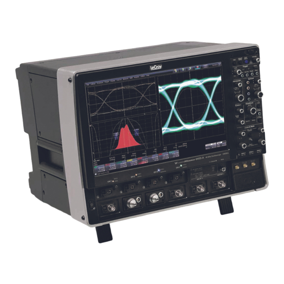
WaveMaster 8 Zi/Zi-A Oscilloscopes Hardware The Front of Your Oscilloscope Numbered labels on this image correspond with descriptions on the following table. Number and Description 1. Power Button 5. Volume Control 9. USB Ports 2. Channel Row and Mute Button 10. -
Page 15: Front Panel
Getting Started Manual Front Panel Detaching and Attaching the Front Panel Control Detach the Front Panel Control from the oscilloscope by sliding the detachment lever to the left and pulling at the right. Attach the front panel by inserting the lower part first, sliding the detachment lever to the left, and then pushing the top in place. - Page 16 USB - A to USB - Mini B cable provided. Note: While a standard front panel comes with your Zi oscilloscope, Teledyne LeCroy offers additional standard front panels or a 4 channel version (as follows) to better suit the way you work. Learn more and Contact Teledyne LeCroy for Support.
-
Page 17: Input/Output Panel
Input/output connectors are sometimes located on the right side (facing the front of the instrument) or on the rear of the instrument: WaveMaster 8 Zi / Zi-A oscilloscopes I/O panel Numbers on this image of the I/O Panel correspond with descriptions on the following table. -
Page 18: The Back Of Your Oscilloscope
WaveMaster 8 Zi/Zi-A Oscilloscopes The Back of Your Oscilloscope Numbers on this image correspond with descriptions in the following table. Back of the WaveMaster 8 Zi. Number and Description 1. 10 MHz Reference 2. 10 MHz Reference 4. DVD-CD + R Drive... -
Page 19: Basic Controls
Getting Started Manual Basic Controls Front Panel Controls The front panel is divided into sections based on various functions. Note: Many Front Panel Controls duplicate Display controls. For example, depending on how it is configured, the front panel Print button duplicates the File >... - Page 20 WaveMaster 8 Zi/Zi-A Oscilloscopes Miscellaneous Controls / WaveStream Indicator Help - Press to open the Teledyne LeCroy Online Assistant where you can click to open the oscilloscope online help table of contents, index, or search for a topic using a keyword. If the second monitor is installed, the online help opens on the second monitor.
-
Page 21: Trigger Front Panel Controls
Getting Started Manual Perform an autosetup of all these functions together by pressing the Auto Setup... front panel button. WaveStream - Indicates when WaveStream mode is ON. Intensity - Press to toggle between WaveStream OFF and ON for Analog Persistence and WaveStream ON for Color Persistence. -
Page 22: Horizontal Front Panel Controls
WaveMaster 8 Zi/Zi-A Oscilloscopes signal meets the trigger conditions set for the type of trigger selected. If the scope is already armed, it will force a trigger. Stop - Press to prevent the scope from triggering on a signal. If you boot up the instrument with the trigger in Stop mode, a no trace available message is shown. -
Page 23: Vertical Front Panel Controls
Getting Started Manual Vertical Front Panel Controls Note: You can turn channels on and off using the software as explained in Vertical Overview (on page 54). Channels - The channel buttons control both channel ON/OFF and which channel is active for the Vertical Offset and Volts/Div knobs controls. -
Page 24: Zoom And Math Front Panel Controls
WaveMaster 8 Zi/Zi-A Oscilloscopes Zoom and Math Front Panel Controls Note: Zoom and Math front panel controls correspond with screen menu selection: Math → Zoom Setup.. Horizontal Position - Press to reset the horizontal zoom position to zero. Turn to change the horizontal position of the selected math or zoom trace. -
Page 25: Probe And Signal Interfaces
Getting Started Manual Probe and Signal Interfaces Overview Teledyne LeCroy oscilloscopes are equipped with a variety of connection interfaces to allow connection of cables directly to the oscilloscope channels, or to allow probe connections to the oscilloscope. When probes are connected, a probe interface is used to power the probe (as necessary),... -
Page 26: Probe Interfaces
WaveMaster 8 Zi/Zi-A Oscilloscopes Probe Interfaces Teledyne LeCroy oscilloscopes utilize one or more proprietary probe interfaces providing a complete measurement solution from probe tip to oscilloscope display. Compared to standard BNC and Probe Ring interfaces, this intelligent interconnection between your instrument and the probe or... - Page 27 Getting Started Manual A Teledyne LeCroy Zi series oscilloscope showing the four sets of ProBus/ProLink probe interfaces. Zi oscilloscopes are compatible with all Teledyne LeCroy probes. The following figure shows a typical channel setup dialog on a Teledyne LeCroy oscilloscope containing both ProLink (Input A, Upper) and ProBus (Input B, Lower) interfaces.
-
Page 28: Probus Probe And Cable Connecting Interface
WaveMaster 8 Zi/Zi-A Oscilloscopes When a probe is connected, it is recognized and an additional tab with the probe model name is displayed to the right of the C1 tab. The channel dialog layout showing Input A's ProLink interface controls setup after connection. -
Page 29: Prolink Probe Interface
For more information, refer to Dual Channel Acquisition in the online help. WaveMaster 8 Zi / Zi-A models use 2.92 mm inputs for the 20 - 36 GHz signal inputs and 2.92 mm inputs for the 25 - 36 GHz signal inputs. These... -
Page 30: Prolink Interface Adapters
ProLink Interface Adapters For some instruments, Teledyne LeCroy's ProLink Adapters (LPA) provide the ability to connect a cable to your oscilloscope that is either BNC, SMA, or K (2.92 mm) terminated. These adapters are only for cable connection since they do not provide the power and communication interfaces required for probe usage. -
Page 31: Connecting The Adapters
Getting Started Manual First, the BMA Female Connector (1). Then, shown installed are the ProLink LPA- SMA, LPA-BNC, and LPA-K Adapters (2, 3, and 4). Note: When connecting an active probe to the instrument, an adapter is not required unless you wish to connect a ProBus compatible probe to a ProLink input. -
Page 32: Prolink Probe Adapters
Connecting the ProLink Probe Adapter is done in a similar way as connecting a ProLink Interface Adapter. Probes Teledyne LeCroy offers a variety of passive and active probes for use with your X-Stream oscilloscope. Visit teledynelecroy.com for specifications and ordering information. -
Page 33: Passive Probe Compensation
Getting Started Manual called earth) acts as a zero reference for the test point measurement. Differential Probes - Differential active probes are like two probes in one. Instead of measuring a test point in relation to a ground point (like single-ended active probes), differential probes measure the difference in voltage of a test point in relation to another test point. -
Page 34: Display
WaveMaster 8 Zi/Zi-A Oscilloscopes Display Screen Layout, Groupings, and Controls The instrument's screen is divided into the following main sections: Note: Many front panel controls directly correspond with screen layout controls. For example, the Print front panel general control button corresponds with the Hardcopy function set from Utilities →... -
Page 35: The Quick Access Toolbar
Getting Started Manual The Quick Access Toolbar The Quick Access portion of the toolbar is located on the right side of the menu bar. It contains the Rotate Display button. When the display is rotated, touch this button to adjust the user interface to a portrait layout. - Page 36 WaveMaster 8 Zi/Zi-A Oscilloscopes There are several indicators on the grid to help you understand the following: Trigger Delay - This indicator is located along the bottom edge of the grid. Trigger delay allows you to see the signal prior to the trigger time.
-
Page 37: Trace Descriptor Labels
Getting Started Manual Push the LEVEL knob to reset the level to 50%. Zero Volts Level - This indicator is located at the left edge of the grid. Change the zero volts level by turning the vertical OFFSET knob. Push the knob to reset the indicator to the middle of the grid. - Page 38 WaveMaster 8 Zi/Zi-A Oscilloscopes Make vertical or horizontal channel adjustments by touching the respective label. The setup dialog for the function is shown beneath. Channel trace labels show the vertical settings for the trace and cursor information (if cursors are in use). The title bar of the label includes indicators for (SinX)/X interpolation, waveform inversion (INV), deskew (DSQ), coupling (DC/GND), bandwidth limiting (BWL), and averaging (AVG).
-
Page 39: Annotating Traces
Getting Started Manual Setup information for horizontal cursors, including the time between cursors and the frequency, is shown beneath the TimeBase and Trigger trace descriptor labels. Shortcut Toolbar Buttons You can access the same functions available from the Signal Display Grid Pop-Up menu by clicking a trace-descriptor label and using the toolbar of buttons at the bottom of the setup dialogs. - Page 40 WaveMaster 8 Zi/Zi-A Oscilloscopes From this pop-up you can edit existing annotations, change the label placement on the waveform, add labels, remove labels, and toggle the visibility. The following bullets show you how. If you are modifying an existing label, under Labels touch the label you want to change.
-
Page 41: Dialog Area
Getting Started Manual Add another label by touching the Add label button. Delete a label by selecting the label from the list, and then touching the Remove label button. Make labels visible by touching the View labels checkbox. Dialog Area The lower portion of your oscilloscope screen is where information is shown, selections are made, and data is input. - Page 42 WaveMaster 8 Zi/Zi-A Oscilloscopes Pop-Up Selector Control for values with varied types. NTRY IELDS Most fields can be touched once and you can then provide a value using an attached (or double-touch/click to use the Virtual, on-screen) keyboard. Text entry field for LabNotebook using the Virtual Keyboard.
- Page 43 Getting Started Manual OLDER AVIGATION REES These controls allow for navigation to or from folders (on the hard drive or memory device) for retrieving or storing items such as waveforms, LabNotebook entries, to name a few. The Recall waveform navigation tree. Note: The instrument's hard disk is partitioned into drive C: and drive D:.
- Page 44 WaveMaster 8 Zi/Zi-A Oscilloscopes An example of Flyout Menu Controls is seen in the Setup front panel button. Setup Flyout Menu control. RECISION NTRY ONTROLS Certain fields requiring precise value entry assist you by having precision entry means. When these controls are selected, you can provide values as...
- Page 45 Getting Started Manual Text entry field for LabNotebook using the Virtual Keyboard. Slider Bar Some models provide what is known as a Slider Bar along the bottom of the screen when a keyboard is attached to the instrument. The Slider Bar allows you to select your entered value by moving a horizontal slider (left to right provides low to high amounts).
-
Page 46: Shortcut Toolbar Buttons
WaveMaster 8 Zi/Zi-A Oscilloscopes Default and Keypad Buttons on the Slider Bar are only shown on 7, 8, and 9 Zi models (with a keyboard attached). Shortcut Toolbar Buttons Several dialogs contain common functions accessible from a row of buttons along the bottom of the main setup dialogs. -
Page 47: Message Bar
Getting Started Manual Probe Cal - Cable Deskew - Opens the Probes Cal. dialog where various Gain, Offset, Skew, Source, and Advanced controls are available for probe signal calibration. Another example is seen in the buttons appearing at the bottom of the Measure Px dialogs. -
Page 48: Timebase
WaveMaster 8 Zi/Zi-A Oscilloscopes Whenever you turn on a channel, math, or memory trace using either the menu bar or trace descriptor label, the dialog at the bottom of the screen automatically switches to the vertical setup or math setup dialog for that selection. -
Page 49: Combining Channels
Digital Bandwidth Interleave is a method for combining channels to double bandwidth - just as oscilloscope manufacturers have for years interleaved channels to double sample rate and memory lengths. Teledyne LeCroy's 8 Zi-A series makes use of 6th generation DBI technology providing the highest possible performance. - Page 50 WaveMaster 8 Zi/Zi-A Oscilloscopes Check Don't Show Me This Message Again to avoid subsequent warnings. The 2.92 mm connector saver pop-up. The 2.4 mm connector saver pop-up. When selected, the respective channels are combined into one channel at higher bandwidth. The 45 GHz model contains a button to combine all four channels into one (C3) channel at 45 GHz bandwidth.
- Page 51 Getting Started Manual PLEASE NOTE THE FOLLOWING: For 25 or 30 GHz models, you may elect to combine one or both pairs of channels. Combined channel buttons have a 30 or 45 GHz label depending on your model. When these buttons are selected, the channel pair (or group on 45 GHz models) is dedicated to achieving that level of bandwidth throughput together.
- Page 52 WaveMaster 8 Zi/Zi-A Oscilloscopes Note: After you've enabled DBI for C3 and/or C2, and corresponding trace dialogs are shown on the display, respective channel LED indicators are also lit on the front of the oscilloscope. DBI Settings When you use DBI and make correct connections and channel selections from the TimeBase →...
-
Page 53: Sampling Modes
Getting Started Manual Sampling Modes Overview Depending on your timebase, you can choose Single-shot Sampling Mode (below), also known as Real Time mode, Sequence Sampling Mode (on page 46), or RIS Sampling Mode (on page 53) mode sampling. Newer instruments offer Roll Mode (on page 54) Some instruments also offer Roll Mode (on page 54). -
Page 54: Sequence Sampling Mode - Working With Segments
WaveMaster 8 Zi/Zi-A Oscilloscopes You can sample the waveform in a range starting well before the trigger event up to the moment the event occurs. This is 100% pre-trigger, and it allows you to see the waveform leading up to the point at which the trigger condition was met and the trigger occurred. -
Page 55: Sequence Display Modes
Getting Started Manual You can combine sequence mode with an advanced trigger to isolate a rare event, capture all instances over hours or days, and view/analyze each afterwards. You can use Sequence mode in remote operation to take full advantage of the instrument's high data-transfer capability. -
Page 56: Sequence Mode Setup
WaveMaster 8 Zi/Zi-A Oscilloscopes Waterfall (cascaded) Mosaic (tiled) Overlay Perspective Note: some display modes have limitations on the number of segments that can be shown at one time. Sequence Mode Setup When setting up Sequence Mode, you define the number of fixed-size segments acquired in single-shot mode (see the instrument specifications for the limits). - Page 57 Getting Started Manual and total available memory to determine the actual number of samples or segments, and time or points. Setting up Sequence Mode (Adjacent) 1. Touch Timebase → Horizontal Setup... on the menu bar. 2. Click the Sequence tab. 3.
-
Page 58: Zooming Segments In Sequence Mode
WaveMaster 8 Zi/Zi-A Oscilloscopes waits indefinitely for an unforthcoming segment. During that time, no oscilloscope functions are accessible. By means of a timeout value, however, the acquisition will be completed, the waveform displayed, and control of the oscilloscope returned to the user after the timeout has elapsed. - Page 59 Getting Started Manual 1. Touch the front panel Quickzoom button. 2. Turn the Z front panel position knob to scroll through the segments. 3. To vary the degree of zoom, touch the newly created Zx trace label. The setup dialog for the zoom (Z1 to Z4) opens. It shows the current horizontal and vertical zoom factors.
-
Page 60: Displaying An Individual Segment
WaveMaster 8 Zi/Zi-A Oscilloscopes Displaying an Individual Segment 1. Touch Math → Math Setup... on the menu bar. 2. Touch a function tab Fx showing its corresponding dialog. 3. On the dialog, touch inside the Operator1 control and select the Segment button from the pop-up menu. -
Page 61: Ris Sampling Mode For Higher Sampling Rates
Getting Started Manual 1. Touch Timebase → Acquisition Status on the menu bar. Touch Vertical → Channel Status on the menu bar. 2. Touch the Trigger Time tab. 3. Under Show Status For, touch the Time button. 4. Touch inside the Select Segment control and enter a segment number value (you can also touch the arrow buttons to scroll through segment times). -
Page 62: Roll Mode
WaveMaster 8 Zi/Zi-A Oscilloscopes Note: RIS mode is not available when the oscilloscope is operating in fixed sample or DBI 25 - 45 GHz) modes as covered in Smart Memory (available in the online help files) and Combining Channels topics, respectively. -
Page 63: Channel Controls
Getting Started Manual Channel Controls The individual Channel Controls section of the dialog provides the following functions for your respective channel: Channel Inputs - For each channel, you can set the Channel Input to either Input A (Upper) or Input B (Lower). The Channel Row LED Indicators display which input is set for each channel. -
Page 64: Setting Up Channels
WaveMaster 8 Zi/Zi-A Oscilloscopes Probe - Teledyne LeCroy's ProLink, and 2.92 mm systems automatically senses probes and sets their attenuation for you. For each channel, the probe attenuation can also be set manually. Setting Up Channels 1. Touch Vertical → Channelx Setup... from the menu bar. -
Page 65: Shortcut Toolbar Buttons
Getting Started Manual 8. Touch inside the Probe Atten. data entry control if you want to set the attenuation manually, and provide a value using your preferred input control method. Additional information on using the touch screen controls can be found in the Dialog Area (on page 33). Shortcut Toolbar Buttons Shortcut Toolbar buttons provide quick access to various functions for your respective channel. -
Page 66: Pre-Processing Controls
WaveMaster 8 Zi/Zi-A Oscilloscopes Pre-Processing Controls Pre-Processing is meant as before Math processing. Pre-Processing controls provide the following functions for your respective channel: Averaging - Specifically performs continuous averaging or the repeated addition, with unequal weight, of successive source waveforms. -
Page 67: Response Optimization Modes
Note: The Cable De-Embedding checkbox is only available if you have the option. Learn more about this software option and Contact Teledyne LeCroy for Support. Interpolation - Linear interpolation, which inserts a straight line between sample points, is best used to reconstruct straight-edged signals such as square waves. - Page 68 WaveMaster 8 Zi/Zi-A Oscilloscopes Teledyne LeCroy provides three choices for Response Optimization Mode selection. These choices combine a frequency and group delay response to optimize the oscilloscope for particular applications. Pulse Response - A group delay compensation minimizing preshoot,...
-
Page 69: Trigger
Getting Started Manual Flatness - Flat group delay compensation with a brick-wall frequency response. While this provides the fastest rise time, there is also a slight penalty of more preshoot and overshoot compared to Eye Diagram mode. This selection is most often used in narrow-band RF measurements where it is desired to maintain constant magnitude response over the oscilloscope passband. -
Page 70: Trigger Types
A simple trigger, Edge trigger is activated by basic waveform features or conditions such as positive or negative slope, and holdoff. Note: On WaveMaster 8 Zi and Zi-A, up to 15 GHz bandwidth is available while Edge Triggering (provided no holdoff is selected). - Page 71 Getting Started Manual Width trigger allows you to define a positive- or negative-going pulse width bounded by a voltage level, above or below an occurring trigger. Or you can specify a pulse width and voltage range, within or outside an occurring trigger.
- Page 72 WaveMaster 8 Zi/Zi-A Oscilloscopes LITCH Glitch trigger is a simpler form of Width trigger. Use Glitch trigger when you want to define a fixed pulse-width time or time range only. Glitch trigger makes no provision for voltage levels or ranges.
- Page 73 Getting Started Manual Not available on all instruments, TV triggers provide stable triggering on standard or custom composite video signals. Use them on PAL, SECAM, NTSC, or HDTV systems. MulitStage Touching this MultiStage trigger type shows the additional MultiStage types on the dialog. Select from Cascaded, QualFirst, and Qualified as follows: ASCADED The Cascaded trigger allows you to define successive trigger Stages...
-
Page 74: Serial Trigger
WaveMaster 8 Zi/Zi-A Oscilloscopes UALIFIED In single trigger mode, Qualify A-B arms the oscilloscope on the A event, and then triggers on the B event. If the oscilloscope is in Normal trigger mode, it automatically resets after the B event. Arm trigger events can be set for Edge, Pattern, State, and PatState. -
Page 75: Trigger Settings
Getting Started Manual Trigger Settings Horizontal and Vertical adjustments are typically made for all trigger types using either the Delay or Level knobs on the front panel of the instrument or their respective controls on the Timebase setup dialog. Horizontal: Turn the D knob in the HORIZONTAL control group ELAY to adjust the trigger's horizontal position. -
Page 76: Trigger Setup
WaveMaster 8 Zi/Zi-A Oscilloscopes Trigger Setup Based on your Trigger Type selection, sections of the main Trigger dialog and additional dialogs altogether vary. Most trigger types have Type, Setup, and Level selections. The following sections explain some of the standard setup configurations for different trigger types. - Page 77 Getting Started Manual Edge trigger works on the selected edge at the chosen level. The slope (positive or negative) is specified on the Trigger label permanently shown to the lower-right of the grid. 5. Level defines the source voltage at which the trigger circuit generates an event (a change in the input signal that satisfies the trigger conditions).
-
Page 78: Optimize For Hf
WaveMaster 8 Zi/Zi-A Oscilloscopes Optimize for HF The Optimize for HF checkbox can be used on an Edge trigger to reject high or low frequencies. The checkbox is marked by default; meaning, the instrument is optimized for high-frequency waveforms. Note: If you are measuring a waveform that is 10 MHz or slower, be sure to unmark the checkbox to avoid triggering on an incorrect slope. - Page 79 Getting Started Manual Now, click the corresponding control and provide a value. Use holdoff to obtain a stable trigger for repetitive, composite waveforms. For example, if the number or duration of sub-signals is known you can disable them by choosing an appropriate holdoff value. Qualified triggers operate using conditions similar to holdoff.
-
Page 80: Auxiliary Input Trigger
WaveMaster 8 Zi/Zi-A Oscilloscopes FF BY VENTS Select a positive or negative slope and a number of events. An event is the number of times the trigger condition is met after the last trigger. A trigger is generated when the condition is met after this number, counted from the last trigger. -
Page 81: Triggerscan
Getting Started Manual TriggerScan TriggerScan is a debugging tool (available for any trigger type) that helps you quickly find rare waveform glitches and anomalies. With TriggerScan, you can build a list of trigger setups to look for rare events and automatically sequence through each one. -
Page 82: Training Triggerscan
WaveMaster 8 Zi/Zi-A Oscilloscopes Training TriggerScan The TriggerScan Trainer inspects a currently acquired waveform and automatically builds a list of common trigger setups used to find rare events. PLEASE NOTE THE FOLLOWING: You must acquire and display at least 3 cycles of a signal before running the Trainer. -
Page 83: Starting Triggerscan
Getting Started Manual Starting TriggerScan After you have run the Trainer, the Trigger List displays a list of smart trigger setups. You can add or remove trigger setups. You can also update the selected smart trigger setup. Once you have made any changes to the Trigger List, you are ready to start scanning. -
Page 84: Saving Triggerscan Setups
WaveMaster 8 Zi/Zi-A Oscilloscopes PLEASE NOTE THE FOLLOWING: You can tune the dwell time that the oscilloscope waits before loading the next trigger setup using the Dwell Time data entry control. If you have Persistence display mode enabled, all trigger events are recorded on the display. -
Page 85: Viewing Waveforms
In order to accomplish this while still providing the ability to view many signals at one time on the oscilloscope display Teledyne LeCroy provides multi-grid capability. This creates multiple oscilloscope grids, each with 8-bit vertical resolution, and allows many full-resolution grids (but vertically smaller in grid height) for concurrent display without affecting the vertical resolution. -
Page 86: Display Setup
WaveMaster 8 Zi/Zi-A Oscilloscopes Display Setup Access and adjust the different display configurations on our oscilloscope using the following steps: Note: Not all grid styles are available on all instruments. Grid styles vary based on both oscilloscope model and whether or not you have the SDAII software option loaded on your oscilloscope. - Page 87 Getting Started Manual 3. Touch inside the Grid Intensity data entry control (as follows). Provide a value from 0 to 100. 4. Touch the Grid on top checkbox if you want to superimpose the grid over the waveform. Note: Depending on the grid intensity, some of your waveforms may be hidden from view when the grid is placed on top.
-
Page 88: Moving Traces From Grid To Grid
WaveMaster 8 Zi/Zi-A Oscilloscopes 5. Touch inside the trace Intensity data entry control if you want to change the value. Enter a value from 0 to 100. Note: Access the Monitor tab for external monitor display settings. Refer to the External Display topic for more details. -
Page 89: Displays Containing Masks
Getting Started Manual Note: If you have more than one waveform displayed on only one grid, a second grid automatically opens when you select Next Grid. Displays Containing Masks Since masks are pixel-based display renderings, you can think of them as part of the Display feature set on your instrument. -
Page 90: Persistence
WaveMaster 8 Zi/Zi-A Oscilloscopes 1. Touch the Dual button on the Display Mode section of the Display dialog. 2. Touch inside the Grid control on the Grid Mode section of the dialog. The Select Grid pop-up is shown. 3. Touch the Dual Display category and choose from Single/Single, Dual/Dual, and Quad/Quad options. - Page 91 Getting Started Manual 4. Touch inside the Saturation data entry control and provide a whole number integer. For more information on saturation, see the Saturation Level topic. 5. Touch inside the Persistence time data entry control and make a selection from the pop-up menu. Individual Persistence Setup for Each Channel 1.
-
Page 92: Wavestream Display Mode
WaveMaster 8 Zi/Zi-A Oscilloscopes WaveStream Display Mode This fast viewing mode provides brightness-graded intensity with a decay time similar to the action of phosphor on an analog screen. WaveStream mode operates at up to 80 GS/s with an update rate of up to several thousand waveforms/second for better capture of higher frequency abnormal events. -
Page 93: Zooming Waveforms
Getting Started Manual indicates most frequent occurrences while blue denotes the less frequent. Instead of using the knob, you can provide values for Intensity (same control on Display and Persistence dialogs) or Saturation controls. Zooming Waveforms Overview You can magnify a selected region of a waveform using the Zoom function. On Zi model oscilloscopes, you can display up to four Zoom (Z1 - Z4) and eight Math Zoom traces (F1 - F8). -
Page 94: Zooming A Single Channel
WaveMaster 8 Zi/Zi-A Oscilloscopes Zooming a Single Channel 1. On the menu bar, touch Vertical → Channel X Setup..Touch the channel trace descriptor label for a displayed channel. 2. Touch the Zoom at the bottom of the Cx Vertical Adjust dialog. A zoom trace (one of Z1 to Z4) is created for the selected channel. - Page 95 Getting Started Manual If you want to zoom in or out in large standard increments with each touch of the zoom control buttons, leave the Var. checkbox unchecked. If you want to set exact horizontal or vertical zoom factors, touch inside the Horizontal Scale/div data entry control and provide a time-per-div value using your preferred input control method.
-
Page 96: Touch-And-Drag Zooming
WaveMaster 8 Zi/Zi-A Oscilloscopes Touch-and-Drag Zooming 1. Touch and drag a rectangle around any part of an input channel waveform, math trace, or memory trace. The Zoom (Z1 to Z4) dialog opens. Note: If you have enclosed a combination of channel and math or memory traces in the rectangle, a pop-up Rectangle Zoom Wizard is shown. -
Page 97: Measuring With Cursors
Getting Started Manual Measuring with Cursors Overview Cursors are important tools that aid you in measuring signal values. Cursors are markers - lines, cross-hairs, or arrows - that you can move around the grid or the waveform itself. Use cursors to make fast, accurate measurements and eliminate guesswork. -
Page 98: The Cursors Dialog
WaveMaster 8 Zi/Zi-A Oscilloscopes PLEASE NOTE THE FOLLOWING: The bottom cursor knob adjusts relative cursors. It does not work with absolute cursor types. Previously setup cursor positions are preserved for subsequent displays. Changing cursor positions or measurement modes are always available using touch screen or front panel control methods as previously mentioned. -
Page 99: Cursors On Math Functions
Getting Started Manual Vertical Abs - Provides a single, dashed, horizontal line and cross- hair marking for the specific cursor location. None of the Show controls are provided; however, the Position 1 control is enabled on the right of the dialog. ELATIVE URSOR YPES... -
Page 100: Measurement Parameters
WaveMaster 8 Zi/Zi-A Oscilloscopes Measurement Parameters Overview Parameters are measurement tools that determine a wide range of waveform properties. Use them to automatically calculate many attributes of your waveform, like rise-time, rms voltage, and peak-to-peak voltage, for example. There are parameter modes for the amplitude and time domains, custom parameter groups, and parameters for pass and fail testing. -
Page 101: Parameter Setup
Performs math (addition, subtraction, multiplication, division) on parameters indicated on the Source1 and Source2 controls. Advanced Web Edit Selecting this type uses Teledyne LeCroy's Processing Web for measurement setup. This feature, available with the XWEB option, allows you to chain practically unlimited math functions together for operation on your waveform measurements. - Page 102 WaveMaster 8 Zi/Zi-A Oscilloscopes If you selected Math On Parameters, touch inside the Math Operator data entry field and select a math function from the pop- up menu. 5. In the mini-dialog to the right of the main setup dialog, touch the Gate tab to narrow the span of measurement - as covered in the Measure Gate topic (available in the online help files).
-
Page 103: Measure Modes
Getting Started Manual Measure Modes The selections for Measure Mode allow you to quickly apply parameters for standard vertical and standard horizontal setups, and custom setups. Standard Vertical Parameters These are the default Standard Vertical Parameters: Vertical mean sdev max. min. - Page 104 WaveMaster 8 Zi/Zi-A Oscilloscopes You have a choice of Simple or Detailed views of the markers: The Simple selection produces cursors and Measure Gate gate posts. The gate posts are independently placeable for each parameter. The Detailed selection produces cursors, Measure Gate gate posts, a...
-
Page 105: Help Markers Setup
Getting Started Manual Help Markers Setup 1. Touch Measure → Measure Setup... on the menu bar. 2. Select a Measure Mode: Std Vertical, Std Horizontal, or My Measure. 3. Touch the Show All button (as follows) to display Help Markers for every parameter being measured on the displayed waveform (C2 in the previous examples). -
Page 106: Measurement Parameter Analysis
WaveMaster 8 Zi/Zi-A Oscilloscopes Measurement Parameter Analysis Overview Teledyne LeCroy provides a variety of unique capabilities for advanced measurement parameter analysis. Most Teledyne LeCroy oscilloscopes calculate measurements for all instances in the acquisition. This provides the ability to rapidly and thoroughly analyze a long memory acquisition and calculate thousands or millions of parameter values, or find anomalous measurements. -
Page 107: Creating And Viewing A Histogram
Getting Started Manual Differences between Track and Trend are summarized in the following table: Characteristic Track Trend Representation Parameter value vs. event Parameter value vs. time Behavior Non-cumulative Cumulative over several acquisitions (resets after every up to 1 million events acquisition). -
Page 108: Single Parameter Histogram Setup
WaveMaster 8 Zi/Zi-A Oscilloscopes PLEASE NOTE THE FOLLOWING: The number of sweeps comprising the histogram is shown on the trace descriptor label: The range of a histogram is limited to the portion of the trace that is visible on screen. That is, if you zoom in on a trace, the histogram does not contain data for that part of the original (no longer visible) trace. - Page 109 Getting Started Manual Using a Corresponding Px Tab/Dialog - After directly accessing a corresponding Px dialog, touch the Measure control and the Select Measurement pop-up is shown. Regardless of how you performed the previously described initial steps, at this point access your corresponding Px dialog to change other setup items as follows: 1.
- Page 110 WaveMaster 8 Zi/Zi-A Oscilloscopes 1. On the Buffer side of the Histogram right-hand dialog, touch #Values and provide a value. 2. On the Scaling side of the Histogram right-hand dialog, touch #Bins and provide a value. 3. Center the histogram by touching the Find Center and Width button.
- Page 111 Getting Started Manual Using a Corresponding Fx Tab/Dialog - After directly accessing a corresponding Fx dialog, touch the Operator control and the Select Math Operator pop-up is shown. Regardless of how you performed the previously described initial steps, at this point access your corresponding Fx dialog if you want to change other setup items as follows: ...
-
Page 112: Persistence Histogram
WaveMaster 8 Zi/Zi-A Oscilloscopes 2. Touch the Histicons checkbox to display thumbnail histograms below the selected parameters. Note: For measurements set up in My Measure, you can quickly display an enlarged histogram of a thumbnail histogram by touching the Histicon you want to enlarge. -
Page 113: Creating And Viewing A Trend
Getting Started Manual Persistence Trace Range Using this math operator, you can enter the percent of the persistence trace population to use in creating a new waveform. Note: See previous sections for details around setting up a math trace and selecting your math operator if needed. -
Page 114: Creating A Track View
WaveMaster 8 Zi/Zi-A Oscilloscopes Note: Turning off a trace for which trend data is being collected resets the trend. If it is necessary to continue data collection for the trend, first create a zoom trace of the channel trace (before turning off the channel trace). -
Page 115: Pass-Fail Parameter Testing
Getting Started Manual 7. Touch the newly displayed Track math function trace label if you want to change any settings in the Track dialog: Pass-Fail Parameter Testing Access the main Pass/Fail dialog by selecting Analysis → Pass/Fail Setup... from the menu bar. The main Pass/Fail dialog is shown. Access the respective Qx dialogs either by touching a Qx button on this main Pass/Fail dialog, or touching a Qx tab as described in Displays Containing Masks (on page 81). - Page 116 WaveMaster 8 Zi/Zi-A Oscilloscopes Use either these checkboxes or the ones on each respective Qx dialog to enable the specific condition for use. When you have each of the Qx dialogs configured and enabled as desired, you can then begin your testing and turn them all on or off using the Testing checkbox on the main Pass/Fail dialog.
- Page 117 Getting Started Manual Pass/Fail Setup on Qx Dialogs The Qx dialog contains several controls for specifying your Pass/Fail setup. IALOG ONTROLS Use the Source1 control to specify the waveform you'll use for your Condition. Set your Pass/Fail condition by touching the Condition control on the corresponding Qx dialog.
- Page 118 WaveMaster 8 Zi/Zi-A Oscilloscopes Using the Param Compare conditions, each Pass/Fail input (Qx) can compare a different parameter result to a user-defined limit (or statistical range) under a different condition. OMPARING A INGLE ARAMETER 1. With the ParamCompare condition selected on a Qx dialog, touch inside the Compare Values field and select All or Any from the pop- up menu.
- Page 119 Getting Started Manual OMPARING ARAMETERS In Dual Parameter Compare mode, your oscilloscope can take parameter results measured on two different waveforms and compare them to each other. If desired, set your test to be true if Any or All waveforms fit the criteria set by the comparison condition.
-
Page 120: The Actions Dialog
WaveMaster 8 Zi/Zi-A Oscilloscopes 8. Touch inside the Limit field and enter a value, using the pop-up numeric keypad. This value takes the dimension of the parameter that you are testing. For example, if you are testing a time parameter, the unit is seconds. - Page 121 Getting Started Manual Depending on your oscilloscope model, you can configure up to 8 pass/fail conditions. The Boolean conditions to determine if your waveform passes are as follows: Pass/Fail Boolean Conditions All True All False Any True Any False All Q1 to Q4 Or All Q5 to Q8 Any Q1 to Q4 And Any Q5 to Q8 ESTING ETUP...
-
Page 122: Math
Math Overview Teledyne LeCroy offers a deep toolset of math functions always growing and changing to provide superior functionality. Note: To find out which math tools are available in each optional package or for any detailed explanations about specific functionality, it's always a... -
Page 123: Math Setup
Getting Started Manual having trace F2 provide the average of F1 having trace F3 provide the integral of F2 go even further and display the integral of the averaged difference between Channels 1 and 2. You can even chain traces and/or functions to another trace or function. For instance: ... - Page 124 WaveMaster 8 Zi/Zi-A Oscilloscopes You can modify the source of your waveform used on a Math trace using the source (Source 1) control. Touch the Single function button if you want to perform just one math function on the trace, or touch the Dual function button to perform math on math (shown respectively, as follows).
-
Page 125: Mask Testing
Getting Started Manual Mask Testing Users may load or create a pixel-based mask on the display grid using a variety of methods. Test conditions can be set, and a pass/fail result returned based on whether the condition was found to be true or false. The source of the mask is always a trace (Channel, Zoom, Math waveform). -
Page 126: Quick Access To Pass/Fail Setup Dialogs
WaveMaster 8 Zi/Zi-A Oscilloscopes 3. With the Mask test Pass Fail Condition selected, the Test, Load Mask, Make Mask, and Gate right-hand dialogs are shown and are where you manage, make, and apply gates to your mask. For more detailed information about these right-hand dialogs, refer to Pass/Fail Testing (on page 107). -
Page 127: Right-Hand Dialogs
Getting Started Manual Mask testing can be done using an existing mask, or by using a mask created from your actual waveform, with vertical and horizontal tolerances that you define. Existing masks can be loaded from a floppy disk or from a network. -
Page 128: Wavescan Overview
WaveMaster 8 Zi/Zi-A Oscilloscopes When loading a pre-existing mask, use the Load Mask right-hand dialog. Using the File button, you can then enter the file name or browse to its location. When creating a new mask, use the Make Mask right-hand dialog. -
Page 129: Signal Views
Getting Started Manual Signal Views Source View highlights all occurrences of edges that meet your criteria. Scan Overlay places all captured edges one on top of the other in a separate grid. You can apply monochromatic persistence in this view. -
Page 130: Search Modes
WaveMaster 8 Zi/Zi-A Oscilloscopes Search Modes Use the Mode control to select an appropriate Search to locate anomalies during acquisition. When each of the following modes are selected, a corresponding right-hand dialog provides additional controls. The following modes are available: ... -
Page 131: Customization Overview
Getting Started Manual Customization Overview The instrument provides powerful capability to add your parameters, functions, display algorithms, or other routines to the oscilloscope user interface. You can customize the instrument to your needs by using the power of programs such as Excel™, Mathcad™, and MATLAB™, or by scripting in VBS. -
Page 132: Documenting Your Work Using Labnotebook
Documenting Your Work Using LabNotebook Overview Teledyne LeCroy's LabNotebook feature extends the documentation capabilities of your oscilloscope. It allows you to create an annotated notebook entry containing all displayed waveforms, the setup of the DSO, and user-supplied annotations. The notebook entry can then be converted to hardcopy format - .pdf, .rtf, or .html - and printed or e-mailed. -
Page 133: Labnotebook Dialog
Getting Started Manual LabNotebook Dialog When LabNotebook is accessed by File → LabNotebook on the menu bar, the main LabNotebook dialog is shown by default. This dialog is where you can store and create LabNotebook entries. You also can View, Create, E-Mail, and select an output format for your reports. -
Page 134: Notebook Entries
WaveMaster 8 Zi/Zi-A Oscilloscopes PLEASE NOTE THE FOLLOWING: When an entry is first created and Report Title and Description information is provided, your new entry is shown along with The Drawing Toolbar at the top of the screen. When finished and the Done button is touched from the Drawing Toolbar, your new entry is shown on the My Notebook Entries list. - Page 135 Getting Started Manual accumulated data from multiple acquired waveforms, they lose their history and show instead only the results from the stored waveforms. You can use the Up and Down arrows to move through your My Notebook Entries list one row at a time. If you have a large amount of entries, touch the Filter button and the Filter Entries pop-up is shown.
- Page 136 WaveMaster 8 Zi/Zi-A Oscilloscopes The E-Mail button automatically sends the report data to the account you've specified in Preferences. See, E-Mail (on page 153) for more information. The More Actions button shows the Specific Entry dialog for the entry selected on the My Notebook Entries list. Using this dialog is explained in Managing Notebook Entry Data in the online help.
-
Page 137: Save/Recall
Getting Started Manual Save/Recall Overview The Save/Recall section allows for storage and retrieval of Waveforms, Table Data, and Instrument Setups. It even provides Disk Utilities for arranging the file/folder structure on your instrument's hard drive. Directly access each Save/Recall dialog (Waveform, Table, Setups, and Disk Utilities on the File menu on the menu bar. -
Page 138: Saving And Recalling Setups
WaveMaster 8 Zi/Zi-A Oscilloscopes Saving and Recalling Setups The Save/Recall Setup dialogs allow for quick saving and recalling of up to six oscilloscope panel settings internally on your instrument. If desired, you can also save and recall your oscilloscope panel settings as an .lss file to a specific hard disk location, a network location, or USB drive. -
Page 139: Saving And Recalling Waveforms
Getting Started Manual Each Recall button is labeled with a corresponding setup storage slot. If a setup is stored, SetupX is shown along with the date/time of the save, otherwise, the slot is labeled Empty. ECALLING ETUP IRECTLY FROM A Recall your setup(s) directly from a file by using controls on the Recall From File section on the right side of the dialog. - Page 140 5. If you are saving to a file, touch the Data Format control and select a format type. Binary - saves the file to Teledyne LeCroy's binary file format. This format is documented in various Remote Control Manuals for Teledyne LeCroy Oscilloscopes. Selecting Binary results in the smallest possible file size, and is recommended when recalling waveforms to Teledyne LeCroy instruments.
- Page 141 Getting Started Manual Word - Available when selecting the Binary format, specifies the samples in the output file are represented with 16 bits. Always use this option unless Byte mode is pre. Byte - Available when selecting Binary format, specifies the samples in the output file are represented with 8 bits.
-
Page 142: Recalling Waveforms
WaveMaster 8 Zi/Zi-A Oscilloscopes 11. Touch the Browse button next to the Save file in directory control and navigate to the location where you want the file saved. The file name is assigned automatically and is shown under the control. - Page 143 Getting Started Manual 5. When saving a File, touch inside the Show only files control and select an area to limit the search (channels, math functions, or memory). 6. Touch inside the Recall files from directory data entry control and provide the path.
-
Page 144: Utilities
WaveMaster 8 Zi/Zi-A Oscilloscopes Utilities Overview Utilities settings are divided into two main groups: Utilities Setup and Preferences Setup. The Utilities menu also has shortcuts to Disk Utilities (File Menu functions) and Calibration Setup (also found in Preferences). Utilities Setup Selecting Utilities →... - Page 145 New software options can be added after purchasing a code and then enabling the option on the oscilloscope. Call Teledyne LeCroy Customer Support to place an order and receive the code. After adding new software options, the entire oscilloscope application needs to be restarted.
-
Page 146: Remote Communication
GPIB is an option that either requires a GPIB card to be installed in an open card slot on your oscilloscope or the use of an external USB to GPIB Teledyne LeCroy accessory. Your particular oscilloscope may support both, or only one of the options/accessories. For more... -
Page 147: Printing And Hardcopy Functions
Getting Started Manual the oscilloscope's connection if it is already connected to the network or make a new connection. Note: Your instrument allows you to restrict remote control access to certain clients. To restrict access, under Security, touch the Yes button and enter the IP addresses or domain name server names you want to restrict separated by a comma. - Page 148 WaveMaster 8 Zi/Zi-A Oscilloscopes Note: A white background saves printer toner. (You can change the printer colors in the Utilities → Preference Setup → Color dialog.) 4. Touch inside the Select Printer control and choose a printer from the pop-up menu.
- Page 149 Getting Started Manual RINT TO LIPBOARD The Clipboard selection on the Hardcopy tab saves the screen image on the clipboard so you can paste a file into another application (like Microsoft Word, for example). 1. Touch Utilities → Utilities Setup... and click the Hardcopy tab. On the Hardcopy dialog, touch the Clipboard button.
- Page 150 WaveMaster 8 Zi/Zi-A Oscilloscopes 3. Touch inside the File Name data entry control and provide a name for the display image using your preferred input control method. Additional information on using the touch screen controls can be found in the Dialog Area (on page 33).
- Page 151 Getting Started Manual RINTING A CREEN MAGE After the Hardcopy settings are configured, you can print in any of these ways, and the image will be handled according to your desired output type: Press the P front panel button. Then, touch the Print Now RINT button on the Print flyout menu.
-
Page 152: Aux Output
WaveMaster 8 Zi/Zi-A Oscilloscopes Aux Output The Aux Output dialog allows you to specify Auxiliary and Calibration Output details. 1. If you want a specialized output, touch one of the following buttons under Use Auxiliary Output For: Square Wave, Trigger Enabled, Trigger Out, Pass/Fail, or Off. - Page 153 Getting Started Manual gating function to trigger another instrument when the oscilloscope is ready. Trigger Out - This function can be used to trigger an external oscilloscope. Pass/Fail - Allows you to set a pulse duration (varied based on your specific model, refer to datasheet specifications at teledynelecroy.com for details);...
- Page 154 WaveMaster 8 Zi/Zi-A Oscilloscopes Date/Time From the Date and Time tab on the Utilities dialog, you can manually set the time and date or get it from the Internet. If you elect to get the date and time from the Internet, you need to have the oscilloscope connected to the Internet through the LAN connector on your instrument's I/O panel.
-
Page 155: Disk Utilities
Getting Started Manual Disk Utilities Use the Disk Utilities dialog to arrange the file/folder structure on your instrument's hard drive. You can delete files, folders, or create new folders. Note: All Disk Utilities can also be accomplished using the standard Microsoft Windows®... -
Page 156: Preferences Setup
WaveMaster 8 Zi/Zi-A Oscilloscopes 3. Create a Folder by first touching the Create button on the dialog (just to make sure it's selected). Touch inside the Current folder data entry control and provide the path for folder creation and be sure to include the folder name. - Page 157 Getting Started Manual 2. You can choose to have your instrument automatically re-calibrate itself whenever there is a significant change in ambient temperature by marking the Enable checkbox on the Automatic Calibration section of the dialog. Note: If you do not enable this option, the oscilloscope re-calibrates only at startup and whenever you make a change to certain operating conditions.
- Page 158 (provided that the oscilloscope is operated within its specified temperature range). This is a unique capability to LeCroy in that no user intervention is required to maintain warranted specifications. Reduced Calibration Frequency automatically calibrates each unique oscilloscope setting (defined by V/div, time/div, sample rate, temperature, trigger source, etc.) and stores the calibration values in a non-volatile table...
- Page 159 Getting Started Manual Acquisition Access the Acquisition preference settings in the following manner: The Acquisition dialog. Trigger Counter Setting is not available on all models. Numbers on the image correspond with the following explanations. 1. On the Offset Setting constant in area of the dialog, touch either the Div or Volts button.
- Page 160 WaveMaster 8 Zi/Zi-A Oscilloscopes 3. If this checkbox control is available on your oscilloscope, you can mark the Reset trigger counter before starting a new acquisition checkbox on the Trigger Counter Setting area of the dialog. This preference clears the trigger counter each time the oscilloscope...
- Page 161 Getting Started Manual E-Mail Configure this dialog to send email from the oscilloscope. 1. On the E-Mail Server section of the dialog, choose a server protocol from the following options: MAPI (Messaging Application Programming Interface) is the Microsoft interface specification that allows different messaging and workgroup applications (including e-mail, voice mail, and fax) to work through a single client, such as the Exchange client.
- Page 162 WaveMaster 8 Zi/Zi-A Oscilloscopes Color You can customize the Colors used for Channels, Math, and Memory traces both when shown on your instrument and when used in print output. Note: These color settings match a waveform on the grid display (both on- screen and printed) and show consistently on corresponding dialogs, tables, and trace descriptor labels.
- Page 163 Numbers on this image correspond with the following explanations. 1. You can add the Teledyne LeCroy Logo to hardcopies of your grid display waveforms by marking the Print Teledyne LeCroy Logo When Printing Grid Area Only checkbox on the Hardcopy section of the dialog.
-
Page 164: System Recovery
Severe cases may require a reloading of the base operating system and oscilloscope application. Teledyne LeCroy provides you with an Acronis® recovery application and a backup image in an extra partition on the instrument's hard drive. - Page 165 Image Echo Workstation. For more definitive documentation refer to their aforementioned documentation resources. Teledyne LeCroy provides you with a recovery application and a backup image in an extra partition on the instrument's hard drive. The recovery process is easy to perform, using the Recovery Wizard. After the recovery procedure is done, you must activate Windows, either by Internet connection to Microsoft's Web site or by telephone.
- Page 166 WaveMaster 8 Zi/Zi-A Oscilloscopes where the recovery data is located on your oscilloscope) and click Next. 8. On the Backup Date Selection page, choose the date when the backup was created and to which state you want to revert your system and click Next.
-
Page 167: Restarting The Operating System
Getting Started Manual 19. To install Adobe Flash Player, click Install and then Finish. The X- Stream software installer screen appears. 20. Click Next to continue. The License Agreement page is displayed. 21. Click I Agree. The Choose Components page is displayed. 22. -
Page 168: Reference
WaveMaster 8 Zi/Zi-A Oscilloscopes Reference Specifications Please refer to the Teledyne LeCroy website at teledynelecroy.com where detailed specification information is regularly maintained on corresponding product datasheets. Note: Specifications are subject to change without notice. Certifications This section certifies the instrument’s Electromagnetic Compatibility (EMC), Safety and Environmental compliances. - Page 169 5 Performance Criteria “C” applied for 70%/25 cycle voltage dips and for 0%/250 cycle voltage interruption test levels per EN61000-4-11. European Contact: Teledyne LeCroy Europe GmbH Waldhofer Str 104 D-69123 Heidelberg Germany Tel: (49) 6221 82700 &...
-
Page 170: Safety Compliance
WaveMaster 8 Zi/Zi-A Oscilloscopes Safety Compliance EC D – L ECLARATION ONFORMITY OLTAGE The oscilloscope meets intent of EC Directive 2006/95/EC for Product Safety. Compliance was demonstrated to the following specifications as listed in the Official Journal of the European Communities: EN 61010-1:2010 Safety requirements for electrical equipment for measurement, control, and laboratory use –... -
Page 171: Windows License Agreement
Manufactured under an ISO 9000 Registered Quality Management System. Visit teledynelecroy.com to view the certificate. Windows License Agreement Teledyne LeCroy's agreement with Microsoft prohibits users from running software on Teledyne LeCroy X-Stream oscilloscopes that is not relevant to measuring, analyzing, or documenting waveforms. 922133-00 Rev A... -
Page 172: X-Stream Software End-User License Agreement
1. GRANT OF LICENSE. 1.1. License Grant. Subject to the terms and conditions of this EULA and payment of all applicable fees, Teledyne LeCroy grants to you a nonexclusive, nontransferable license (the “License”) to: (a) operate the Software Product as provided or installed, in object code form,... - Page 173 (other than Instruments and Your Software) without the express prior written consent of Teledyne LeCroy. The Software Product is licensed as a single product. Its component parts may not be separated for use by more than one user.
- Page 174 Software Product and to such acts as are necessary to achieve the Permitted Objective; (C) the information to be gained thereby has not already been made readily available to you or has not been provided by Teledyne LeCroy within 922133-00 Rev A...
- Page 175 Getting Started Manual a reasonable time after a written request by you to Teledyne LeCroy to provide such information; (D) the information gained is not used for any purpose other than the Permitted Objective and is not disclosed to any other person except as may be necessary to achieve the Permitted Objective;...
- Page 176 "applets" embodied in or incorporated into the Software Product, collectively, "Content"), and all Derivatives, and any copies thereof are owned by Teledyne LeCroy and/or its licensors or third-party suppliers, and is protected by applicable copyright or other intellectual property laws and treaties. You will not take any action inconsistent with such title and ownership.
- Page 177 Documentation) and other proprietary information of Teledyne LeCroy; and any business, marketing or technical information disclosed by Teledyne LeCroy, or its representatives, or you in relation to this EULA, and either (i) disclosed in writing and marked as confidential at the time of disclosure or (ii) disclosed in any other manner such that a reasonable person would understand the nature and confidentiality of the information.
- Page 178 DFARS §227.7202. The use of the Software Product or Documentation by the Government constitutes acknowledgment of Teledyne LeCroy's proprietary rights in the Software Product and Documentation. Manufacturer is Teledyne LeCroy Corporation, 700 Chestnut Ridge Road, Chestnut Ridge, NY 10977 USA.
- Page 179 ALL WARRANTIES IMPLIED FROM ANY COURSE OF DEALING OR USAGE OF TRADE. YOU ACKNOWLEDGE THAT NO WARRANTIES HAVE BEEN MADE TO YOU BY OR ON BEHALF OF TELEDYNE LECROY OR OTHERWISE FORM THE BASIS FOR THE BARGAIN BETWEEN THE PARTIES.
- Page 180 Teledyne LeCroy, its agents, or employees, but only by an instrument in writing signed by an authorized officer of Teledyne LeCroy. No waiver by Teledyne LeCroy of any breach or default of any provision of this EULA by you 922133-00 Rev A...
- Page 181 8.6. Notices. All notices or other communications between Teledyne LeCroy and you under this EULA will be in writing and delivered personally, sent by confirmed fax, by confirmed e-mail, by certified mail, postage prepaid and return receipt requested, or by a nationally recognized express delivery service.
-
Page 182: Contact Teledyne Lecroy
WaveMaster 8 Zi/Zi-A Oscilloscopes Contact Teledyne LeCroy Teledyne LeCroy Service Centers United States and Canada - United States - Protocol Solutions Group World Wide Corporate Office Teledyne LeCroy Corporation Teledyne LeCroy Corporation 3385 Scott Boulevard 700 Chestnut Ridge Road Santa Clara, CA, 95054, USA... -
Page 183: Index
Getting Started Manual Index cursors setup, 98 Cursors, 100 2.92 mm and 2.4 mm Probe and customization Cable Connection Interface, 24 connectivity, 136 Customization Overview, 136 Acquisition, 165 actions, 123 data formats, 145 Actions for Trace Buttons, 35, 42 Date/Time, 159 Actions for Trace C1 Buttons, 63 DBI, 46 active probe, 26... - Page 184 WaveMaster 8 Zi/Zi-A Oscilloscopes Find Scale, 63 Flashback (Recall), 139 LabNotebook Front Panel Controls, 14 drawing toolbar, 138 LabNotebook Overivew, 137 LeCroy External Display (Zi- EXTDISP-15) Setup, 11 grid intensity, 87 Level, 77 grid on top, 87 Linear, 65 hardcopy setup, 153...
- Page 185 Getting Started Manual Quick Access to Pass/Fail Setup Originator Address (From, 167 Dialogs, 130 Overview of E-Mail modes, 167 Quickly Displaying Cursors, 98 Parameter Measurements, 135 recalling default scope settings, parameter setup, 102 parameters Recalling Setup(s) Directly from a measure modes, 104 File, 144 standard vertical, 104 Recalling Setup(s) Internally on...
- Page 186 WaveMaster 8 Zi/Zi-A Oscilloscopes Saving Setup(s) Internally on Your SNTP, 159 Instrument, 143 Source, 75 Saving TriggerScan Setups, 84 Specifications, 174 Saving Waveforms, 144 Starting TriggerScan, 83 Screen Layout, Groupings, and status of scope, 150 Controls, 30 Search Modes, 134...
- Page 187 Getting Started Manual coupling, 76 holdoff, 78 Vertical Front Panel Controls, 18 trigger types, 69 view aux in, 80 trigger types, 69 TriggerScan, 81 Turning, 101 WaveML data format, 146 Turning on Channels and Traces, WaveScan Overview, 133 WaveStream, 92 Type, 75 Width, 78 Windows operating system, 173...
- Page 188 WaveMaster 8 Zi/Zi-A Oscilloscopes 922133-00 Rev A...
Need help?
Do you have a question about the WaveMaster 8 Zi and is the answer not in the manual?
Questions and answers