LeCroy WaveMaster 8 Zi Getting Started Manual
Oscilloscopes
Hide thumbs
Also See for WaveMaster 8 Zi:
- Getting started manual (190 pages) ,
- Getting started manual (196 pages) ,
- Getting started manual (201 pages)
Table of Contents
Advertisement
Quick Links
Advertisement
Table of Contents

Related Manuals for LeCroy WaveMaster 8 Zi


Summary of Contents for LeCroy WaveMaster 8 Zi
-
Page 1: Getting Started
Getting Started M anual WaveM aster 8 Zi and Zi-A Oscilloscopes... - Page 2 WaveMaster 8 Zi and Zi-A Oscilloscopes December, 2011...
- Page 3 LeCroy shall not be responsible for any defect, damage, or failure caused by any of the following: a) attempted repairs or installations by personnel other than LeCroy representatives or b) improper connection to incompatible equipment, or c) for any damage or malfunction caused by the use of non-LeCroy supplies.
-
Page 4: Table Of Contents
Detaching and Attaching the Front Panel Control .. 24 The I/O Panel ............26 The Back of Your Oscilloscope ......... 29 LeCroy External Display (Zi-EXTDISP-15) Setup ..30 Basic Controls ............32 Hardware and Software Controls ......32 Front Panel Controls ..........32... - Page 5 WaveMaster 8 Zi and Zi-A Oscilloscopes Front Panel Control Groupings ....... 34 Front Panel Control Groupings Overview ....34 Trigger Front Panel Controls ........35 Horizontal Front Panel Controls ......36 Vertical Front Panel Controls ........37 Zoom and Math Front Panel Controls ..... 38 Probe and Signal Connection Interfaces .....
- Page 6 Getting Started Manual Actions for Trace Buttons ........63 Message Bar ............64 Turning on Channels and Traces ......... 65 Timebase ..............66 Timebase Overview ..........66 Timebase Setup and Control ........66 Combining Channels ..........66 Sampling Modes ............72 Sampling Modes Overview ........
- Page 7 WaveMaster 8 Zi and Zi-A Oscilloscopes Trigger Types ............92 Edge ................. 92 Width ..............92 Pattern (Logic) ............92 Smart ............... 93 Measurement ............94 TV ................95 MulitStage ............... 95 Serial Trigger ............96 Trigger Settings ............97 Trigger Setup ............
- Page 8 Getting Started Manual WaveStream Display Mode ........117 Adjusting Trace Intensity ........117 Zooming Waveforms ..........119 Zooming Waveforms Overview ......119 Previewing Zoomed Waveforms ......120 Zooming a Single Channel ........120 Touch-and-Drag Zooming ........122 Turning Off Zoom ..........123 Measuring with Cursors ...........
- Page 9 WaveMaster 8 Zi and Zi-A Oscilloscopes Single Parameter Histogram Setup ....... 138 Viewing Thumbnail Histograms (Histicons) ..142 Persistence Histogram .......... 143 Persistence Trace Range ........144 Persistence Sigma ..........144 Creating and Viewing a Trend ....... 144 Creating a Track View ........... 145 Pass-Fail Parameter Testing ........
- Page 10 Getting Started Manual LabNotebook ............170 Save/Recall ............. 175 Save/Recall Overview ..........175 Saving and Recalling Setups ........176 Saving Oscilloscope Setup(s) ......... 176 Recalling Oscilloscope Setup(s) ......176 Recalling Default Settings ........177 Saving and Recalling Waveforms ......177 Saving Waveforms ..........
- Page 11 CERTIFICATIONS ............ 213 CE Declaration of Conformity ....... 213 EMC Directive ............213 Low-Voltage Directive ........... 214 UL and cUL ............215 Contact LeCroy for Support ........215 China RoHS Compliance ........218 ® Windows License Agreement ......231 Index ............... 232...
-
Page 12: Welcome
Getting Started Manual Welcome Welcome Thank you for purchasing a LeCroy product. We're certain you'll be pleased with the detailed features so unique to our instruments. This WaveMaster8 Zi and Zi-A Getting Started Manual is designed to cover important safety and installation information for your oscilloscope, along with standard procedures so you're quickly working on waveforms. -
Page 13: Reference
Save/Recall Utilities Reference The Reference section is set aside and covers items like Certifications (on page 213) and how to Contact LeCroy for Support (on page 215). The LeCroy website at www.lecroy.com always maintains the most current specification information. The website should always be checked for frequent updates. -
Page 14: Safety Requirements
Getting Started Manual Safety Requirements This section contains information and warnings that must be observed to keep the instrument operating in a correct and safe condition. You are required to follow generally accepted safety procedures in addition to the safety precautions specified in this section. Safety Symbols Where the following symbols appear on the instrument's front or rear panels, or in this manual, they alert you to important safety... - Page 15 WaveMaster 8 Zi and Zi-A Oscilloscopes Off (Supply). This is the AC mains connect/disconnect switch at the back of the instrument (if provided). This symbol shows that the switch is a Standby (power) switch located on the front of the oscilloscope. Pressing this button toggles the oscilloscope's state between operating and Standby mode.
-
Page 16: Operating Environment
Getting Started Manual CAT I Installation (Overvoltage) Category rating per EN 61010-1 safety standard and is applicable for the oscilloscope front panel measuring terminals. CAT I rated terminals must only be connected to source circuits in which measures are taken to limit transient voltages to an appropriately low level. -
Page 17: Safety Certification
WaveMaster 8 Zi and Zi-A Oscilloscopes CAUTION Do not exceed the maximum specified front panel terminal voltage ratings. Refer to Specifications for more details. The specifications for maximum allowable voltages are located on a label on the front of the oscilloscope. -
Page 18: Cooling
Getting Started Manual Cooling The instrument relies on forced air cooling with internal fans and ventilation openings. Care must be taken to avoid restricting the airflow around the apertures (fan holes) on any side of the oscilloscope. For sides and rear apertures, ensure adequate ventilation by leaving the required 10 cm (4 inch) minimum gap around the sides and rear of the instrument. -
Page 19: Power And Ground Connections
WaveMaster 8 Zi and Zi-A Oscilloscopes Power consumption in Standby Mode: 22 Watts. Power and Ground Connections The instrument is provided with a 15A/250V 14AWG rated grounded cord set containing a molded three-terminal polarized plug and a specific IEC-60320 (Type C15) connector for making line voltage and safety ground connections. - Page 20 Getting Started Manual Standby (Power) Switch and Oscilloscope Operational States On some models, the Standby (Power) switch controls the operational state of the oscilloscope. This toggle switch is activated by momentarily pressing and releasing it. Also on certain models, the color of the LED below the switch indicates the status of the oscilloscope as follows: ...
-
Page 21: Calibration
WaveMaster 8 Zi and Zi-A Oscilloscopes The oscilloscope can always be placed in the Standby state (LED Off) – Power Off (except for some housekeeping circuits) by pressing and holding in the Standby toggle switch for approximately 5 seconds. CAUTION Hibernate mode is not supported by the Power button. -
Page 22: Abnormal Conditions
Getting Started Manual Abnormal Conditions Operate the instrument only as intended by the manufacturer. If you suspect the oscilloscope's protection has been impaired, disconnect the power cord and secure the instrument against any unintended operation. The oscilloscope's protection is likely to be impaired if, for example, the instrument shows visible damage or has been subjected to severe transport stresses. -
Page 23: Hardware
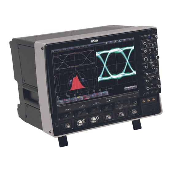
WaveMaster 8 Zi and Zi-A Oscilloscopes Hardware The Front of Your Oscilloscope Numbered labels on this image correspond with descriptions on the following table. Number and Description 1. Power Button 5. Volume Control 9. USB Ports 2. Channel Row and Mute 10. -
Page 24: Detaching And Attaching The Front Panel Control
Getting Started Manual Detaching and Attaching the Front Panel Control Detach the Front Panel Control from the oscilloscope by sliding the detachment lever to the left and pulling at the right. Attach the front panel by inserting the lower part first, sliding the detachment lever to the left, and then pushing the top in place. - Page 25 USB - A to USB - Mini B cable provided. Note: While a standard front panel comes with your Zi oscilloscope, LeCroy offers additional standard front panels or a 4 channel version (as follows) to better suit the way you work. Learn more and Contact LeCroy for Support (on page 215).
-
Page 26: The I/O Panel
Getting Started Manual The I/O Panel The I/O Panel is sometimes located on the right side (facing the front of the instrument) or the rear of the instrument (depending on the model) as follows: The WavePro 7 Zi oscilloscope's I/O panel its back. WM8Zi-A-GSM-E RevC... - Page 27 WaveMaster 8 Zi and Zi-A Oscilloscopes The WaveMaster 8 Zi oscilloscope's I/O panel its back. WM8Zi-A-GSM-E RevC...
- Page 28 Numbered labels on this image of the I/O Panel correspond with descriptions on the following table. The exact location does vary on WavePro 7 Zi, Zi-A and WaveMaster 8 Zi, Zi-A and the other Zi instruments. Number and Description 1. LBUS (LeCroy 5. External VGA 10. PCI Expansion Bus) Monitor Slots for DVI (for 2.
-
Page 29: The Back Of Your Oscilloscope
WaveMaster 8 Zi and Zi-A Oscilloscopes The Back of Your Oscilloscope Numbered labels on this image correspond with descriptions on the following table. Back of the WaveMaster 8 Zi. The back is similar to the 7 and 9 Zi models as well. -
Page 30: Lecroy External Display (Zi-Extdisp-15) Setup
Getting Started Manual LeCroy External Display (Zi-EXTDISP-15) Setup Setting up the Zi-EXTDISP-15 involves a DVI-D and USB connections and some touch screen selections. The USB connection is a hot swap, so there's no need to restart the instrument once you've connected. - Page 31 WaveMaster 8 Zi and Zi-A Oscilloscopes 4. The Intel® Graphics Media Accelerator Driver interface is shown where you can adjust your second monitor settings. The following picture shows a WavePro 7 Zi with the LeCroy external display attached (optional ZI-EXTDISP-15). WM8Zi-A-GSM-E RevC...
-
Page 32: Basic Controls
Getting Started Manual Basic Controls Hardware and Software Controls The following Basic Control topics cover the general usage of the hardware buttons located on the oscilloscope's front panel and the screen control interface elements of the software. Front Panel Controls Note: Many specific Front Panel Controls directly correspond with Screen Layout Controls. - Page 33 WaveMaster 8 Zi and Zi-A Oscilloscopes The following picture shows the Front Panel Control. Front Panel for LabMaster, WaveMaster, and WavePro, Zi and Zi-A oscilloscopes. WM8Zi-A-GSM-E RevC...
-
Page 34: Front Panel Control Groupings
Miscellaneous Setup Controls and WaveStream Indicator Help - Press to open the LeCroy Online Assistant where you can click to open the oscilloscope online help table of contents, index, or search for a topic using a keyword. If the second monitor is installed, the online help opens on the second monitor. -
Page 35: Trigger Front Panel Controls
WaveMaster 8 Zi and Zi-A Oscilloscopes Press a Channel Find Scale button on the flyout menu to perform a quick auto setup for that channel only. Press the A ETUP front panel button twice to perform the last selection from the Auto Setup... -
Page 36: Horizontal Front Panel Controls
Getting Started Manual Setup - Press once to open the Trigger Setup... dialog. Corresponds with screen menu selection: Trigger → Trigger Setup..Press the Trigger S front panel button again to close ETUP the Trigger Setup... dialog. Auto - Press to turn on Auto Trigger mode, which triggers the oscilloscope after a time-out, even if the trigger conditions are not met. -
Page 37: Vertical Front Panel Controls
WaveMaster 8 Zi and Zi-A Oscilloscopes Time/Div - Turn to set the time/division of the oscilloscope timebase (acquisition system). Vertical Front Panel Controls Note: You can turn channels on and off using the software as explained in Vertical Overview (on page 83). ... -
Page 38: Zoom And Math Front Panel Controls
Getting Started Manual Zoom and Math Front Panel Controls Note: Zoom and Math front panel controls correspond with screen menu selection: Math → Zoom Setup.. Horizontal Position - Press to reset the horizontal zoom position to zero. Turn to change the horizontal position of the selected math or zoom trace. -
Page 39: Probe And Signal Connection Interfaces
Interfaces Probe and Signal Connection Interfaces Overview LeCroy oscilloscopes are equipped with a variety of connection interfaces to allow connection of cables directly to the oscilloscope channels, or to allow probe connections to the oscilloscope. When probes are connected, a probe interface is used to power the probe (as necessary),... -
Page 40: Probe Interfaces
Front of the oscilloscope. Probe Interfaces Probe Interfaces Overview LeCroy oscilloscopes utilize one or more proprietary probe interfaces providing a complete measurement solution from probe tip to oscilloscope display. Compared to standard BNC and Probe Ring interfaces, this intelligent interconnection between your instrument and... - Page 41 WaveMaster 8 Zi and Zi-A Oscilloscopes A LeCroy Zi series oscilloscope showing the four sets of ProBus/ProLink probe interfaces. Zi oscilloscopes are compatible with all LeCroy probes. The following figure shows a typical channel setup dialog on a LeCroy oscilloscope containing both ProLink (Input A, Upper) and ProBus (Input B, Lower) interfaces.
-
Page 42: Probus Probe And Cable Connecting Interface
Getting Started Manual When a probe is connected, it is recognized and an additional tab with the probe model name is displayed to the right of the C1 tab. The channel dialog layout showing Input A's ProLink interface controls setup after connection. -
Page 43: Prolink Probe Interface
2.92 mm and 2.4 mm Probe and Cable Connection Interface LeCroy's highest bandwidth oscilloscopes utilize a 2.92mm (up to 36 GHz) or a 2.4mm (up to 45 GHz) probe interface. This interface consists of a precision connector and a LEMO power and communication connector. It offers 50 Ω... -
Page 44: Prolink Interface Adapters
ProLink Interface Adapters For some instruments, LeCroy's ProLink Adapters (LPA) provides the ability to connect a cable to your oscilloscope that is either BNC, SMA, or K (2.92 mm) terminated. These adapters are only for cable connection since they do not provide the power and communication interfaces required for probe usage. - Page 45 WaveMaster 8 Zi and Zi-A Oscilloscopes The following cable connections are supported: BNC, using the LPA-BNC Blind Mate Adapter (BMA) to BNC interface adapter. This is not normally provide with your oscilloscope, but may be ordered as an accessory. ...
-
Page 46: Connecting The Adapters
Getting Started Manual Connecting the Adapters The mating end of the ProLink adapter has four fastening clips (shown right). When installing an adapter on the instrument's connector panel, align the male 6-pin connector with the female connector and push the adapter straight forward. -
Page 47: Probes
WaveMaster 8 Zi and Zi-A Oscilloscopes Probes LeCroy offers a variety of passive and active probes for use with your X- Stream oscilloscope. Visit www.lecroy.com for specifications and ordering information. Current Probes - Current Probes measure the current passing through a wire;... - Page 48 Getting Started Manual 1. Attach the connector end of your passive probe to any channel. 2. Connect the probe end to the CAL output connector at the front of the oscilloscope. Ground the probe. 3. Adjust the trim pot at the connector end of the probe until the square wave is as flat as possible.
-
Page 49: Display Dashboard
WaveMaster 8 Zi and Zi-A Oscilloscopes Display Dashboard Display Dashboard Overview This section covers the various aspects of the user interface shown in the display of your instrument. Screen Layout, Groupings, and Controls The instrument's screen is divided into the following main sections: ... -
Page 50: The Quick Access Toolbar
Getting Started Manual Specific Menu Bar functions are referenced using arrow-separated path descriptions. For example, the Save Setup function is referenced as File → Save Setup..PLEASE NOTE THE FOLLOWING: For common oscilloscope operations, you don't need to use the top menu bar (since you can access most dialogs from the Front Panel or from the Descriptor Labels). -
Page 51: The Signal Display Grid
WaveMaster 8 Zi and Zi-A Oscilloscopes The Signal Display Grid The grid area is divided into 8 vertical divisions and 10 horizontal divisions just like any other oscilloscope. Set up the signal display area by touching Display → Display Setup... from the menu bar. The Display dialog offers a choice of grid combinations and can also set the grid intensity. - Page 52 Getting Started Manual The default setting (Time) is for delay readout (in seconds) and to move proportionately when the timebase knob is turned. If you want to set delay (Div) to a fixed position on the grid, and then have it stay fixed as the timebase changes, go to Utilities → Preference Setup...
-
Page 53: Signal Display Grid Pop-Up Menu
WaveMaster 8 Zi and Zi-A Oscilloscopes Signal Display Grid Pop-Up Menu On the Signal Display Grid, the Pop-up menu provides assistance while using the oscilloscope. Clicking on a waveform opens a pop-up menu. From this pop-up menu, you can perform the following functions: ... - Page 54 Getting Started Manual These indicators have a long and short form, respectively. The long and short forms of trace descriptor indicators. Besides channel traces, math and parameter measurement labels are also displayed. Labels are displayed only for traces that are turned on. Vertical and horizontal trace descriptor (labels) are displayed below the grid.
-
Page 55: Actions For Trace Buttons
WaveMaster 8 Zi and Zi-A Oscilloscopes Actions for Trace Buttons You can access the same functions as the ones produced when using the Signal Display Grid Pop-Up menu just by clicking a trace-descriptor label, which shows its corresponding dialog. From the respective dialog, you're able to access the same functions as Actions for Trace X buttons. - Page 56 Getting Started Manual to create the label. The first time creating a waveform label, Label1 is provided as default text when the Add label button is touched. From this pop-up you can edit existing annotations, change the label placement on the waveform, add labels, remove labels, and toggle the visibility.
-
Page 57: Dialog Area
WaveMaster 8 Zi and Zi-A Oscilloscopes If you want to change the label's text, touch inside the Label Text field. A pop-up keyboard appears for you to enter your text. Touch O.K. on the keyboard when you are done. The edited text automatically appears in the label on the waveform. -
Page 58: Wm8Zi-A-Gsm-E Revc
Getting Started Manual Other times, a larger box is shown after touching a control. This larger Pop-Up has categorical buttons along the left column along with labels (and sometimes descriptions) for the selectable entry values. Pop-Up Selector Control for values with varied types. WM8Zi-A-GSM-E RevC... - Page 59 WaveMaster 8 Zi and Zi-A Oscilloscopes NTRY ONTROLS Most controls can be touched once and you can then provide a value using an attached (or double-touch/click to use the Virtual, on-screen) keyboard. Text entry field for LabNotebook using the Virtual Keyboard. WM8Zi-A-GSM-E RevC...
- Page 60 Getting Started Manual OLDER ROWSING ONTROLS These controls allow for navigation to or from folders (on the hard drive or memory device) for retrieving or storing items such as waveforms, LabNotebook entries, to name a few. Folder/File Browsing recall waveform controls. Note: The instrument's hard disk is partitioned into drive C: and drive D:.
- Page 61 WaveMaster 8 Zi and Zi-A Oscilloscopes LYOUT ONTROLS Flyout Menus provides a variety of solutions for a particular main area of functionality. It does this by providing a set of buttons subdividing the control into more specific functions on the right-side of the display. An example of Flyout Menu Controls is seen in the Setup front panel button.
- Page 62 Getting Started Manual Keyboard Touch inside a text entry control and you can manually type the value in using an attached (or double-touch/click to use the Virtual, on-screen) keyboard. Text entry field for LabNotebook using the Virtual Keyboard. Slider Bar Some models provide what is known as a Slider Bar along the bottom of the screen when a keyboard is attached to the instrument.
-
Page 63: Actions For Trace Buttons
WaveMaster 8 Zi and Zi-A Oscilloscopes For many controls, once the Pop-Up Keypad is shown the Front Panel Controls (on page 32) can be used to adjust the value in the pop-up. The Pop-Up contains Up and Down arrow buttons, Set to Max, Default, and Min buttons, and the Keypad itself for providing your value. -
Page 64: Message Bar
Getting Started Manual Find Scale - Automatically performs a vertical scaling that fits the waveform into the grid. Next Grid - Automatically moves the channel trace whose dialog is currently open onto the next grid. If you have only one grid displayed, a new grid will be created automatically, and the trace moved. -
Page 65: Turning On Channels And Traces
WaveMaster 8 Zi and Zi-A Oscilloscopes Turning on Channels and Traces PLEASE NOTE THE FOLLOWING: If you want to display each trace on its own grid automatically, enable Autogrid by touching Display → Autogrid from the menu bar. You can turn channels on and off using the software, for more information see Vertical Overview (on page 83) ... -
Page 66: Timebase
Getting Started Manual Timebase Timebase Overview You can access Timebase settings using the front panel Horizontal controls, the Timebase → Horizontal Setup... on the menu bar, or by touching the Timebase trace descriptor label. The main Timebase dialog is then shown and contains sections for Sampling Mode, Timebase Mode, and Real Time Memory. - Page 67 - just as oscilloscope manufacturers have for years interleaved channels to double sample rate and memory lengths. LeCroy's 8 Zi-A series makes use of 6th generation DBI technology providing the highest possible performance. Enter DBI mode from the TimeBase dialog at TimeBase → Horizontal Setup..
- Page 68 Getting Started Manual Mark the Don't Show Me This Message Again checkbox to avoid subsequent warnings. The 2.92 mm connector saver pop-up. The 2.4 mm connector saver pop-up. WM8Zi-A-GSM-E RevC...
- Page 69 WaveMaster 8 Zi and Zi-A Oscilloscopes When selected, the respective channels are combined into one channel at higher bandwidth. The 45 GHz model contains a button to combine all four channels into one (C3) channel at 45 GHz bandwidth. PLEASE NOTE THE FOLLOWING: ...
- Page 70 Getting Started Manual On 45 GHz models, DBI can be enabled in two channel mode to achieve performance identical to that of the 30 GHz model, or it can be enabled on the C3 trace to achieve: 45 GHz ...
- Page 71 WaveMaster 8 Zi and Zi-A Oscilloscopes The channel LEDs form the following configuration in 45 GHz mode: Channel 1 Channel 2 Channel 3 Channel 4 OFF, No LED OFF, No LED Green Down OFF, No LED Light Light Arrow Light ▲...
-
Page 72: Sampling Modes
Getting Started Manual Sampling Modes Sampling Modes Overview Depending on your timebase, you can choose Single-shot Sampling Mode (below), also known as Real Time mode, Sequence Sampling Mode (on page 73), or RIS Sampling Mode (on page 80) mode sampling. Newer instruments offer Roll Mode (on page 82) Some instruments also offer Roll Mode (on page 82). - Page 73 WaveMaster 8 Zi and Zi-A Oscilloscopes You can sample the waveform in a range starting well before the trigger event up to the moment the event occurs. This is 100% pre-trigger, and it allows you to see the waveform leading up to the point at which the trigger condition was met and the trigger occurred.
-
Page 74: Sequence Display Modes
Getting Started Manual You can zoom segments or used them as input to math functions. You can combine sequence mode with an advanced trigger to isolate a rare event, capture all instances over hours or days, and view/analyze each afterwards. ... -
Page 75: Sequence Mode Setup
WaveMaster 8 Zi and Zi-A Oscilloscopes Waterfall (cascaded) Mosaic (tiled) Overlay Perspective Note: some display modes have limitations on the number of segments that can be shown at one time. Sequence Mode Setup When setting up Sequence Mode, you define the number of fixed-size segments acquired in single-shot mode (see the instrument specifications for the limits). - Page 76 Getting Started Manual Along with this setting, the oscilloscope uses the number of segments, maximum segment length, and total available memory to determine the actual number of samples or segments, and time or points. Setting up Sequence Mode (Adjacent) 1. Touch Timebase → Horizontal Setup... on the menu bar. 2.
- Page 77 WaveMaster 8 Zi and Zi-A Oscilloscopes Note: Use the sequence mode timeout to automatically interrupt the sequence acquisition if the timeout value is exceeded without a valid trigger. The timeout period accounts for instances when a Num Segments miscount occurs for some reason and the oscilloscope waits indefinitely for an unforthcoming segment.
-
Page 78: Zooming Segments In Sequence Mode
Getting Started Manual Zooming Segments in Sequence Mode You can zoom individual segments easily using the Q front UICKZOOM panel button. When you zoom, the zoom traces default to Segment 1. Channel descriptors indicate the total number of segments acquired. Zoom descriptors indicate [Seg #] and #Segments in the Zoom. -
Page 79: Displaying An Individual Segment
WaveMaster 8 Zi and Zi-A Oscilloscopes 4. If you want to increase or decrease your horizontal or vertical zoom in small increments, touch the Var. checkbox to enable variable zooming. Now with each touch of the zoom control buttons, the degree of magnification changes by small increments. If you want to zoom in or out in large standard increments with each touch of the zoom control buttons, leave the Var. -
Page 80: Viewing Time Stamps
Getting Started Manual Note: In Persistence mode, the segments are automatically overlaid one on top of the other in the display. In non-Persistence mode, they appear separately on the grid. Viewing Time Stamps You can view time stamps for each segment. View Segment Time Stamps 1. - Page 81 WaveMaster 8 Zi and Zi-A Oscilloscopes The maximum effective RIS sampling rate is achieved by making multiple single-shot acquisitions at maximum real-time sample rate. The bins thus acquired are positioned approximately 5 ps (200 GS/s) apart. The process of acquiring these bins and satisfying the time constraint is a random one.
-
Page 82: Roll Mode
Getting Started Manual Roll Mode Roll mode displays, in real time, incoming points in single-shot acquisitions that have a sufficiently low data rate. The oscilloscope rolls the incoming data continuously across the screen until a trigger event is detected and the acquisition is complete. The parameters or math functions connected to each channel are updated every time the roll mode buffer is updated, as if new data is available. -
Page 83: Vertical
WaveMaster 8 Zi and Zi-A Oscilloscopes Vertical Vertical Overview You can access Vertical settings using the front panel Vertical controls, by selecting Vertical→ Channel Setup... on the menu bar, or by touching the Channel trace descriptor label. The following screen-shot shows the C1 Vertical dialog on a LabMaster as an example. - Page 84 Getting Started Manual Vertical Offset - For each channel, you can select between zero vertical offset or to set the offset to a specific value. Coupling - The maximum input voltage depends on the input used. Values are displayed on the front of the oscilloscope. Whenever the voltage exceeds this limit, the coupling mode automatically switches from DC 50 Ω...
-
Page 85: Setting Up Channels
WaveMaster 8 Zi and Zi-A Oscilloscopes Probe - LeCroy's ProBus, ProLink, and 2.92 mm system automatically senses probes and sets their attenuation for you. For each channel, the probe attenuation can also be set manually. Setting Up Channels 1. Touch Vertical → Channelx Setup... from the menu bar. -
Page 86: Actions For Trace C1 Buttons
Getting Started Manual 8. Touch inside the Probe Atten. data entry control if you want to set the attenuation manually, and provide a value using your preferred input control method. Additional information on using the touch screen controls can be found in the Dialog Area (on page 57). -
Page 87: Pre-Processing Controls
WaveMaster 8 Zi and Zi-A Oscilloscopes Pre-Processing Controls Pre-Processing is meant as before Math processing. Pre-Processing controls provide the following functions for your respective channel: Averaging - Specifically performs continuous averaging or the repeated addition, with unequal weight, of successive source waveforms. -
Page 88: Response Optimization Modes
Note: The Cable De-Embedding checkbox is only available if you have the option. Learn more about this software option and Contact LeCroy for Support (on page 215). Interpolation - Linear interpolation, which inserts a straight line between sample points, is best used to reconstruct straight-edged signals such as square waves. - Page 89 When zero group delay is provided at all frequencies, preshoot and overshoot is equalized. LeCroy provides three choices for Response Optimization Mode selection. These choices combine a frequency and group delay response to optimize the oscilloscope for particular applications.
- Page 90 Getting Started Manual Eye Diagram - Flat group delay compensation resulting in equalized preshoot and overshoot. This selection improves the symmetry of serial eye diagrams. In addition, a fourth-order Bessel frequency response is implemented. Flatness - Flat group delay compensation with a brick-wall frequency response.
-
Page 91: Trigger
WaveMaster 8 Zi and Zi-A Oscilloscopes Trigger Trigger Overview Triggering is the way an oscilloscope selects an exact moment in time on a signal to then be shown on the screen. If the pattern of a signal happens to be repetitive, a continuous waveform pattern is inherently visible on the display. -
Page 92: Wm8Zi-A-Gsm-E Revc
In addition, there are more sophisticated triggers for setting basic or complex conditions. These include Smart Triggers, Serial Trigger, Measurement Triggers, and MultiStage Triggers. Learn more and Contact LeCroy for Support (on page 215). Edge A simple trigger, Edge trigger is activated by basic waveform features or conditions such as positive or negative slope, and holdoff. -
Page 93: Smart
WaveMaster 8 Zi and Zi-A Oscilloscopes You have a choice of four Boolean operators (AND, NAND, OR, NOR), and you can stipulate the high or low voltage logic level for each input independently. Smart These are a specific set of sophisticated trigger types. Smart trigger types are used to set conditions on signals with rare features, like the glitches and others as follows: INDOW... -
Page 94: Measurement
Getting Started Manual ROPOUT Used primarily in single-shot applications, and usually with a pre-trigger delay, Dropout trigger can detect lost signals. The trigger is generated at the end of the timeout period following the last trigger source transition. The Runt trigger occurs when a pulse crosses a first threshold line, but fails to cross a second threshold line before re-crossing the first. -
Page 95: Mulitstage
WaveMaster 8 Zi and Zi-A Oscilloscopes Not available on all instruments, TV triggers provide stable triggering on standard or custom composite video signals. Use them on PAL, SECAM, NTSC, or HDTV systems. MulitStage Touching this MultiStage trigger type shows the additional MultiStage types on the dialog. -
Page 96: Serial Trigger
Getting Started Manual UALIFIED In single trigger mode, Qualify A-B arms the oscilloscope on the A event, and then triggers on the B event. If the oscilloscope is in Normal trigger mode, it automatically resets after the B event. Arm trigger events can be set for Edge, Pattern, State, and PatState. -
Page 97: Trigger Settings
WaveMaster 8 Zi and Zi-A Oscilloscopes Clock and Data Recovery (CDR) SERIES-SPECIFIC FEATURE: 80-bit Serial Trigger (without decode capability) is standard on SDA model oscilloscopes and optional on WavePro, WaveMaster, and DDA model oscilloscopes. The CDR feature is optional for the WaveRunner 6 Zi family, including 8b/10b decode. Trigger Settings Horizontal and Vertical adjustments are typically made for all trigger types using either the Delay or Level knobs on the front panel of the... -
Page 98: Trigger Setup
Getting Started Manual Turn this knob to adjust the level of the trigger source or the highlighted trace. Level defines the source voltage at which the trigger will generate an event: a change in the input signal that satisfies the trigger conditions. Alternatively, in the Trigger dialog, you can touch inside the Level control and provide a value using your preferred input control method. - Page 99 WaveMaster 8 Zi and Zi-A Oscilloscopes 2. Touch inside the trigger Source control for your first Setup configuration and select a source on which to trigger. 3. If available, touch inside the Coupling control and select a coupling mode. Coupling refers to the type of signal coupling at the input of the trigger circuit.
- Page 100 Getting Started Manual 4. Touch inside the trigger Slope control and choose the direction of the trigger voltage transition used for generating a particular trigger event. The selection is then shown to the right of the dialog as follows for a Positive Slope selection on an Edge Trigger.
-
Page 101: Optimize For Hf
The Amplitude and Range of the trigger level have limits as detailed in the datasheet specifications regularly maintained on www.lecroy.com. Touch inside the Level data entry control and provide a value using your preferred input control method. Additional information on using the touch screen controls can be found in the Dialog Area (on page 57). -
Page 102: Width Condition Is
Getting Started Manual Width Condition is Width triggers (and other triggers equipped with conditional logic) have conditional logic settings as follows. Your Width Condition can be specified as Less Than, Greater Than, In Range and Out Of Range. In Range and Out Of Range conditions can be further set with Upper and Lower Values (for Limits). - Page 103 WaveMaster 8 Zi and Zi-A Oscilloscopes Now, click the corresponding control and provide a value. Use holdoff to obtain a stable trigger for repetitive, composite waveforms. For example, if the number or duration of sub-signals is known you can disable them by choosing an appropriate holdoff value. Qualified triggers operate using conditions similar to holdoff.
-
Page 104: Auxiliary Input Trigger
Getting Started Manual FF BY VENTS Select a positive or negative slope and a number of events. An event is the number of times the trigger condition is met after the last trigger. A trigger is generated when the condition is met after this number, counted from the last trigger. -
Page 105: Triggerscan
WaveMaster 8 Zi and Zi-A Oscilloscopes TriggerScan TriggerScan is a debugging tool (available for any trigger type) that helps you quickly find rare waveform glitches and anomalies. With TriggerScan, you can build a list of trigger setups to look for rare events and automatically sequence through each one. -
Page 106: Training Triggerscan
Getting Started Manual Training TriggerScan The TriggerScan Trainer inspects a currently acquired waveform and automatically builds a list of common trigger setups used to find rare events. PLEASE NOTE THE FOLLOWING: You must acquire and display at least 3 cycles of a signal before running the Trainer. -
Page 107: Starting Triggerscan
WaveMaster 8 Zi and Zi-A Oscilloscopes Starting TriggerScan After you have run the Trainer, the Trigger List displays a list of smart trigger setups. You can add or remove trigger setups. You can also update the selected smart trigger setup. Once you have made any changes to the Trigger List, you are ready to start scanning. -
Page 108: Saving Triggerscan Setups
Getting Started Manual PLEASE NOTE THE FOLLOWING: You can tune the dwell time that the oscilloscope waits before loading the next trigger setup using the Dwell Time data entry control. If you have Persistence display mode enabled, all trigger events are recorded on the display. -
Page 109: Viewing Waveforms
Channel traces are typically 8-bits of vertical data, whereas Math traces are 16-bits of vertical data. LeCroy grids consist of eight vertical divisions. When displaying channel traces on the grid, use of less than full-grid amplitude results in some reduced vertical resolution and accuracy. -
Page 110: Display Setup
SDAII software option loaded on your oscilloscope. Learn more about software options and Contact LeCroy for Support (on page 215). 1. Touch Display → Display Setup... on the menu bar. - Page 111 WaveMaster 8 Zi and Zi-A Oscilloscopes If more than a certain amount of display setups are available for your oscilloscope, a Grid control is shown and presents the Select Grid pop-up when touched. 3. Touch inside the Grid Intensity data entry control (as follows). Provide a value from 0 to 100.
- Page 112 Getting Started Manual 4. Touch the Grid on top checkbox if you want to superimpose the grid over the waveform. Note: Depending on the grid intensity, some of your waveforms may be hidden from view when the grid is placed on top. To undo, simply uncheck Grid on top.
-
Page 113: Moving Traces From Grid To Grid
WaveMaster 8 Zi and Zi-A Oscilloscopes Touch inside the Num seg displayed control and enter a value, using the pop-up keypad. Touch inside the Starting at control and enter a value. Moving Traces from Grid to Grid You can move traces from grid to grid with the touch of a button. Moving a Channel or Math Trace 1. -
Page 114: Dual Display Grid Selection
Getting Started Manual Dual Display Grid Selection Make a dual grid display selection for showing on an external display (once properly connected to the I/O panel) by selecting Display → Display Setup..Numbered labels on this image correspond with the following steps. -
Page 115: Persistence
WaveMaster 8 Zi and Zi-A Oscilloscopes Persistence Persistence Overview The Persistence feature helps you display your waveform and reveal its idiosyncrasies or anomalies for a repetitive signal. Use Persistence to accumulate on-screen points from many acquisitions to see your signal change over time. - Page 116 Getting Started Manual Persistence Setup for Each Input Channel Individually 1. Touch the Per Trace button. 2. Touch one of the persistence mode buttons next to an input channel. To turn off persistence for an individual channel, touch the left- most persistence mode button next to the channel.
-
Page 117: Wavestream Display Mode
WaveMaster 8 Zi and Zi-A Oscilloscopes WaveStream Display Mode This fast viewing mode provides brightness-graded intensity with a decay time similar to the action of phosphor on an analog screen. WaveStream mode operates at up to 80 GS/s with an update rate of up to several thousand waveforms/second for better capture of higher frequency abnormal events. - Page 118 Getting Started Manual Color Persistence - The button behaves the same way as Analog. However, the grid display shows a color waveform where red indicates most frequent occurrences while blue denotes the less frequent. Instead of using the knob, you can provide values for Intensity (same control on Display and Persistence dialogs) or Saturation controls.
-
Page 119: Zooming Waveforms
WaveMaster 8 Zi and Zi-A Oscilloscopes Zooming Waveforms Zooming Waveforms Overview You can magnify a selected region of a waveform using the Zoom function. On Zi model oscilloscopes, you can display up to four Zoom (Z1 - Z4) and eight Math Zoom traces (F1 - F8). You can zoom: ... -
Page 120: Previewing Zoomed Waveforms
Getting Started Manual Previewing Zoomed Waveforms When you zoom a waveform, a preview of the zoomed area is shown on the Preview section of the Zx dialog. Zooming a Single Channel The Zoom button appears as a standard button at the bottom of the channel Cx Vertical Adjust setup dialog for you to create a zoom trace of your input waveform. - Page 121 WaveMaster 8 Zi and Zi-A Oscilloscopes 3. Vary the degree of zoom by touching the newly created Zx trace label. The setup dialog for the zoom (Z1 to Z4) opens. It shows the current horizontal and vertical zoom factors. 4. If you want to increase or decrease your horizontal or vertical zoom in small increments, touch the Var.
-
Page 122: Touch-And-Drag Zooming
Getting Started Manual Horizontal Ratio - Press to toggle between fixed and variable horizontal zoom ratio adjustment. Turn to change the horizontal zoom ratio of the selected math trace. Quick Zoom - Press to automatically display magnified views of up to four signal inputs on multiple grids. -
Page 123: Turning Off Zoom
WaveMaster 8 Zi and Zi-A Oscilloscopes Quickly Zooming Waveforms and Multiple Waveforms Quickly create a Zoom trace by either pressing the front panel Zoom button or touching the Zoom button on the respective channel dialog. Turning Off Zoom Turn off a Zoom by either pressing the front panel Zoom button again. On the corresponding Zoom dialog, touch the Trace On checkbox to remove the check mark and disable the zoom trace. -
Page 124: Measuring With Cursors
Getting Started Manual Measuring with Cursors Measuring with Cursors Overview Cursors are important tools that aid you in measuring signal values. Cursors are markers - lines, cross-hairs, or arrows - that you can move around the grid or the waveform itself. Use cursors to make fast, accurate measurements and eliminate guesswork. -
Page 125: The Cursors Dialog
WaveMaster 8 Zi and Zi-A Oscilloscopes PLEASE NOTE THE FOLLOWING: The bottom cursor knob adjusts relative cursors. It does not work with absolute cursor types. Previously setup cursor positions are preserved for subsequent displays. Changing cursor positions or measurement modes are always available using touch screen or front panel control methods as previously mentioned. - Page 126 Getting Started Manual Vertical Abs - Provides a single, dashed, horizontal line and cross- hair marking for the specific cursor location. None of the Show controls are provided; however, the Position 1 control is enabled on the right of the dialog. ...
-
Page 127: Cursors On Math Functions
WaveMaster 8 Zi and Zi-A Oscilloscopes Cursors on Math Functions You can place cursors on a math function whose X-axis has a dimension other than time (FFT, for example). With a Math trace setup for either an FFT or a Histogram, if you then access the Standard Cursors dialog (Measure →... -
Page 128: Measurement Parameters
Getting Started Manual Measurement Parameters Measurement Parameters Overview Parameters are measurement tools that determine a wide range of waveform properties. Use them to automatically calculate many attributes of your waveform, like rise-time, rms voltage, and peak-to- peak voltage, for example. There are parameter modes for the amplitude and time domains, custom parameter groups, and parameters for pass and fail testing. -
Page 129: Parameter Setup
Performs math (addition, subtraction, multiplication, division) on parameters indicated on the Source1 and Source2 controls. Advanced Web Edit Selecting this type uses LeCroy's Processing Web for measurement setup. This feature, available with the XWEB option, allows you to chain practically unlimited math functions together for operation on your waveform measurements. - Page 130 Getting Started Manual 4. If you selected Measure On Waveforms, touch inside the Measure field and select a parameter from the pop-up menu. WM8Zi-A-GSM-E RevC...
-
Page 131: Measure Modes
WaveMaster 8 Zi and Zi-A Oscilloscopes If you selected Math On Parameters, touch inside the Math Operator data entry field and select a math function from the pop-up menu. 5. In the mini-dialog to the right of the main setup dialog, touch the Gate tab to narrow the span of measurement - as covered in the Measure Gate topic (available in the online help files). -
Page 132: Standard Vertical Parameters
Getting Started Manual Standard Vertical Parameters These are the default Standard Vertical Parameters: Vertical mean sdev max. min. ampl pkpk base Standard Horizontal Parameters These are the default Standard Horizontal Parameters: Horizontal freq period width rise fall delay duty num points Selecting Measure Modes 1. - Page 133 WaveMaster 8 Zi and Zi-A Oscilloscopes The Detailed selection produces cursors, Measure Gate gate posts, a label identifying the parameter being measured, and a level indicator and hysteresis band for at level parameters (not part of Standard Horizontal or Standard Vertical parameters). Standard Horizontal Parameter Help Markers Standard Vertical Parameter Help Markers WM8Zi-A-GSM-E RevC...
-
Page 134: Help Markers Setup
Getting Started Manual Help Markers Setup 1. Touch Measure → Measure Setup... on the menu bar. 2. Select a Measure Mode: Std Vertical, Std Horizontal, or My Measure. 3. Touch the Show All button (as follows) to display Help Markers for every parameter being measured on the displayed waveform (C2 in the previous examples). - Page 135 WaveMaster 8 Zi and Zi-A Oscilloscopes URNING ARKERS 1. Touch the Clear All button to turn off Help Markers for all parameters. 2. Turn off Help Markers for individual parameters by touching the Px tab for the parameter in question. Then uncheck the AlwaysOn checkbox.
-
Page 136: Measurement Parameter Analysis
Getting Started Manual Measurement Parameter Analysis Measurement Parameter Analysis Overview LeCroy provides a variety of unique capabilities for advanced measurement parameter analysis. Most LeCroy oscilloscopes calculate measurements for all instances in the acquisition. This provides the ability to rapidly and thoroughly analyze a long memory acquisition and calculate thousands or millions of parameter values, or find anomalous measurements. - Page 137 WaveMaster 8 Zi and Zi-A Oscilloscopes Differences between Track and Trend are summarized in the following table: Characteristic Track Trend Parameter value vs. Representation Parameter value vs. event time Behavior Non-cumulative Cumulative over several (resets after every acquisitions up to 1 million acquisition).
-
Page 138: Creating And Viewing A Histogram
Getting Started Manual In general, Track is the tool to use if you want to capture a continuous stream of data spaced closely together. To understand the change in a parameter with time, Trend can be used if your data is spaced widely apart and longer than the dead-time of the oscilloscope between acquisitions. - Page 139 WaveMaster 8 Zi and Zi-A Oscilloscopes There are two ways to select parameters when setting up your measurement. They only differ in the order of the steps. Using the Px Buttons on the Measure Dialog - After directly touching a Px button on the Measure dialog, the Select Measurement pop-up is shown.
- Page 140 Getting Started Manual 3. Touch the Histogram button at the bottom of the dialog. After touching this button, the Math selection for Histogram pop-up is shown. Select the desired Math Trace in which to store the results. Touch the Close button when you are finished. Touch the trace descriptor label for the math trace just created for the results, and then touch the Histogram tab to access its right-hand dialog.
- Page 141 WaveMaster 8 Zi and Zi-A Oscilloscopes INGLE ARAMETER ISTOGRAM ETUP SING Access the main Math dialog by selecting Math → Math Setup... on the menu bar. There are two ways to select your math operator during setup. They only differ in the order of the steps. ...
-
Page 142: Viewing Thumbnail Histograms (Histicons)
Getting Started Manual Regardless of how you performed the previously described initial steps, at this point access your corresponding Fx dialog if you want to change other setup items as follows: You can modify the source of your waveform used on a Math trace using the source (Source 1) control. -
Page 143: Persistence Histogram
WaveMaster 8 Zi and Zi-A Oscilloscopes Note: For measurements set up in My Measure, you can quickly display an enlarged histogram of a thumbnail histogram by touching the Histicon you want to enlarge. The enlarged histogram appears superimposed on the trace it describes. This does not apply to Std Vertical or Std Horizontal measurements. -
Page 144: Persistence Trace Range
Getting Started Manual Persistence Trace Range Using this math operator, you can enter the percent of the persistence trace population to use in creating a new waveform. Note: See previous sections for details around setting up a math trace and selecting your math operator if needed. Persistence Sigma Using this math operation, you can enter a scale, measured in standard deviations, by which to create a new waveform. -
Page 145: Creating A Track View
WaveMaster 8 Zi and Zi-A Oscilloscopes 6. Touch the newly displayed Trend math function trace label to change settings on the Trend dialog (located on the Trend tab at the lower-right side of the screen). Note: Turning off a trace for which trend data is being collected resets the trend. -
Page 146: Pass-Fail Parameter Testing
Getting Started Manual The Track is then shown along with its respective trace descriptor label for the selected math function. 6. Touch the newly displayed Track math function trace label if you want to change any settings in the Track dialog: Pass-Fail Parameter Testing Pass/Fail Parameter Testing Overview Access the main Pass/Fail dialog by selecting Analysis →... -
Page 147: Testing And Enabling Pass/Fail Conditions
WaveMaster 8 Zi and Zi-A Oscilloscopes When you have each of the Qx dialogs configured and enabled as desired, you can then begin your testing and turn them all on or off using the Testing checkbox on the main Pass/Fail dialog. You can also specify Actions for all or some of your conditions using the Actions dialog. -
Page 148: Pass/Fail Setup On Qx Dialogs
Getting Started Manual When you have each of the Qx dialogs configured and enabled as desired, you can then begin your testing and turn them all on or off using the Testing checkbox on the main Pass/Fail dialog. Your test data is shown on the Table display area shown in the previous screen-shot. - Page 149 WaveMaster 8 Zi and Zi-A Oscilloscopes Set your Pass/Fail condition by touching the Condition control on the corresponding Qx dialog. The Pass/Fail Condition pop-up is shown. Select the desired condition. Note: Right hand dialogs back on the corresponding Qx dialog vary based on the Pass/Fail condition selected.
- Page 150 Getting Started Manual Param and Dual Param Compare Using the Param Compare conditions, each Pass/Fail input (Qx) can compare a different parameter result to a user-defined limit (or statistical range) under a different condition. Comparing a Single Parameter 1. With the ParamCompare condition selected on a Qx dialog, touch inside the Compare Values field and select All or Any from the pop-up menu.
- Page 151 WaveMaster 8 Zi and Zi-A Oscilloscopes 3. Touch inside the Limit field and enter a value using the pop-up numeric keypad. The value entered acquires the dimensions corresponding to the parameters being tested. For example, if you are testing a time parameter, the unit is seconds. If you choose either WithinDeltaPct or WithinDeltaAbs from the Condition menu (respectively, previous), you also have the choice of setting the limit by means of the statistical buttons (relating to...
- Page 152 Getting Started Manual 4. Touch inside the Source1 and Source2 fields and select a source from the pop-up menu. 5. Touch inside the ParamCompare mini-dialog field and select a source from the pop-up menu. 6. Touch inside the Compare Values field and select All or Any from the pop-up menu.
-
Page 153: The Actions Dialog
WaveMaster 8 Zi and Zi-A Oscilloscopes 9. If you choose either WithinDeltaPct or WithinDeltaAbs from the Condition menu respectively, touch inside the Delta field and enter a value. The Actions Dialog Various configurations can be made to all or some of your Pass/Fail conditions using the Actions dialog. - Page 154 Getting Started Manual Depending on your oscilloscope model, you can configure up to 8 pass/fail conditions. The Boolean conditions to determine if your waveform passes are as follows: Pass/Fail Boolean Conditions All True All False Any True Any False All Q1 to Q4 Or All Q5 to Q8 Any Q1 to Q4 And Any Q5 to Q8 ESTING ETUP...
- Page 155 WaveMaster 8 Zi and Zi-A Oscilloscopes 8. The Then section of the dialog provides stop test, sound alarm, print result, emit pulse, or save (the waveform) actions. If you want to have the results printed (and your oscilloscope is not equipped with a printer) make sure your instrument is connected to a local or network printer.
-
Page 156: Math
Getting Started Manual Math Math Traces and Functions Overview LeCroy offers a deep toolset of math functions always growing and changing to provide superior functionality. Note: To find out which math tools are available in each optional package or for any detailed explanations about specific functionality,... -
Page 157: Math Setup
WaveMaster 8 Zi and Zi-A Oscilloscopes You can even chain traces and/or functions to another trace or function. For instance: making Trace F1 an average of Channel 1. making Trace F2 an FFT of F1. making Trace F3 a zoom of F2. Math Setup Access the main Math dialog by selecting Math →... - Page 158 Getting Started Manual Regardless of how you performed the previously described initial steps, at this point access your corresponding Fx dialog if you want to change other setup items as follows: You can modify the source of your waveform used on a Math trace using the source (Source 1) control.
-
Page 159: Mask Testing
WaveMaster 8 Zi and Zi-A Oscilloscopes Mask Testing Users may load or create a pixel-based mask on the display grid using a variety of methods. Test conditions can be set, and a pass/fail result returned based on whether the condition was found to be true or false. The source of the mask is always a trace (Channel, Zoom, Math waveform). - Page 160 Getting Started Manual Now, the Q1 dialog is shown and shows the Mask test condition selected. If you touch the Q1 tab, the Q1 dialog is shown. Touching the Condition control shows the same pop-up where you can select the Mask test Pass Fail Condition.
-
Page 161: Quick Access To Pass/Fail Setup Dialogs
WaveMaster 8 Zi and Zi-A Oscilloscopes Quick Access to Pass/Fail Setup Dialogs You can quickly gain access to the main Pass/Fail dialog, a (Qx) setup dialog, or the Actions dialog, by touching one of the following respective sections below the grid display. Removing a Mask from the Display Quickly remove a mask by accessing the Qx dialog. -
Page 162: Right-Hand Dialogs
Getting Started Manual Masks that you create from your waveform can be confined to just a portion of the trace by use of a measure gate. Refer to the Measure Gate online help topic for more information on how this feature works. Right-Hand Dialogs ... - Page 163 WaveMaster 8 Zi and Zi-A Oscilloscopes On the Gate right-hand dialog, you can enter values in the Start and Stop fields to constrain the mask to a portion of the waveform. Or, you can simply touch and drag the Gate posts, which initially are placed at the extreme left and right ends of the grid.
-
Page 164: Wavescan Overview
Getting Started Manual WaveScan Overview WaveScan enables you to search for unusual events in a single capture, or to scan for an event in many acquisitions over a long period of time. You can select from more than 20 search modes (frequency, rise time, runt, duty cycle, etc.), apply a search condition (slope, level, threshold, hysteresis), and begin scanning in a post-acquisition environment. -
Page 165: Signal Views
WaveMaster 8 Zi and Zi-A Oscilloscopes Signal Views WaveScan provides distinct views of your signal: Source View highlights all occurrences of edges that meet your criteria. Scan Overlay places all captured edges one on top of the other in a separate grid. -
Page 166: Parameter Measurements
Getting Started Manual Measurement Mode – Searches from 2 to 64 bits; ideal for bursted patterns where a PLL cannot lock. Bus Pattern Mode – Searches from 2 to 64 bits; enhances MSO search capabilities. Parameter Measurements Besides parameter measurements made during acquisition, post- acquisition measurements can also be made. -
Page 167: Customization Overview
WaveMaster 8 Zi and Zi-A Oscilloscopes Customization Overview The instrument provides powerful capability to add your own parameters, functions, display algorithms, or other routines to the oscilloscope user interface without having to leave the instrument application environment. You can customize the instrument to your needs by using the power of programs such as Excel™, Mathcad™, and MATLAB™, or by scripting in VBS. - Page 168 Getting Started Manual You can do additional processing on the result by applying standard instrument parameters, functions, etc. to the returned result, or even more powerfully, adding chained customized functions. For example, you can do an Excel calculation on a result with a MATLAB function applied to it.
-
Page 169: Documenting Your Work Using Labnotebook
Documenting Your Work Using LabNotebook LabNotebook Overivew LeCroy's LabNotebook feature extends the documentation capabilities of your oscilloscope. It allows you to create an annotated notebook entry containing all displayed waveforms, the setup of the DSO, and user- supplied annotations. The notebook entry can then be converted to hardcopy format - .pdf, .rtf, or .html - and printed or e-mailed. -
Page 170: Wm8Zi-A-Gsm-E Revc
Getting Started Manual LabNotebook When LabNotebook is accessed by File → LabNotebook on the menu bar, the main LabNotebook dialog is shown by default. This dialog is where you can store and create LabNotebook entries. You also can View, Create, E-Mail, and select an output format for your reports. - Page 171 WaveMaster 8 Zi and Zi-A Oscilloscopes Touch inside the Title control and provide a value using your preferred input control method. Additional information on using the touch screen controls can be found in the Dialog Area (on page 57). If desired, touch inside the Description field, provide information and touch Save.
- Page 172 Getting Started Manual Cumulative Measurements - Any measurements on when the Lab Notebook entry is created are not saved individually in the database (other than being embedded in the hardcopy image). This means that when flashback is used, the measurements are recomputed using the recalled waveform data.
- Page 173 WaveMaster 8 Zi and Zi-A Oscilloscopes 5. Use the View, Create Report, and E-Mail buttons as desired. The View button shows a preview of your report. Exit the preview by touching the Close button at the right of the dialog. ...
- Page 174 Getting Started Manual Using this dialog is explained in Managing Notebook Entry Data in the online help. Note: Make personalized settings to your LabNotebook reports using . 6. You can select the Format of your LabNotebook entry from HTML, RTF, and PDF choices. The Delete button removes the specific row selected on the My Notebook Entries list while the Delete All button removes every entry on the list.
-
Page 175: Save/Recall
WaveMaster 8 Zi and Zi-A Oscilloscopes Save/Recall Save/Recall Overview The Save/Recall section allows for storage and retrieval of Waveforms, Table Data, and Instrument Setups. It even provides Disk Utilities for arranging the file/folder structure on your instrument's hard drive. Directly access each Save/Recall dialog (Waveform, Table, Setups, and Disk Utilities on the File menu on the menu bar. -
Page 176: Saving And Recalling Setups
Getting Started Manual Saving and Recalling Setups The Save/Recall Setup dialogs allow for quick saving and recalling of up to six oscilloscope panel settings internally on your instrument. If desired, you can also save and recall your oscilloscope panel settings as an .lss file to a specific hard disk location, a network location, or USB drive. -
Page 177: Recalling Default Settings
WaveMaster 8 Zi and Zi-A Oscilloscopes ECALLING ETUP NTERNALLY ON NSTRUMENT Recall your settings located internally on your instrument by touching inside one of the six Recall buttons on the Recall From Internal Setup... part of the screen. Each Recall button is labeled with a corresponding setup storage slot. If a setup is stored, SetupX is shown along with the date/time of the save, otherwise, the slot is labeled Empty. - Page 178 Getting Started Manual 1. Select either Memory or File by touching either respective button on the Save To portion of the dialog. Note: When Memory is selected, only Source and Destination controls are shown on the Save Waveform dialog. When File is selected, many more controls are available.
- Page 179 5. If you are saving to a file, touch the Data Format control and select a format type. Binary - saves the file to LeCroy's binary file format. This format is documented in various Remote Control Manuals for LeCroy Oscilloscopes. Selecting Binary results in the smallest possible file size, and is recommended when recalling waveforms to LeCroy instruments.
- Page 180 Getting Started Manual Byte - Available when selecting Binary format, specifies the samples in the output file are represented with 8 bits. Note: Using this option can result in a loss of output file resolution. Amplitude only - Specifies the output file include amplitude data for each sample, but not sample time information.
-
Page 181: Recalling Waveforms
WaveMaster 8 Zi and Zi-A Oscilloscopes 6. You can use the Auto Save feature to automatically save a waveform to disk after each new trigger. You can enable Auto Save from the Save Waveform dialog by touching one of the Auto Save buttons. - Page 182 Getting Started Manual Note: When Memory is selected, only Source, Destination, and Show on recall controls are shown on the Recall Waveform dialog. When File is selected, many more controls are available. Regardless, the controls are used as explained in the following steps.
-
Page 183: Utilities
WaveMaster 8 Zi and Zi-A Oscilloscopes Utilities Utilities Setup Utilities Overview Utilities settings are divided into three main sections: Utilities, Disk Utilities, and Preferences as seen when accessing Utilities from the menu bar. Utilities Selecting Utilities → Utilities Setup... shows the main Utilities dialog by default. - Page 184 The Service button is a section of the application reserved for qualified LeCroy personnel. When touched, an access code pop-up is shown enabling LeCroy technicians access to various service dialogs inside the oscilloscope software.
-
Page 185: Status
PTIONS New software options can be added after purchasing a code and then enabling the option on the oscilloscope. Call LeCroy Customer Support to place an order and receive the code. Note: For more information about LeCroy Software Options, Contact LeCroy for Support (on page 215). -
Page 186: Remote Communication
GPIB is an option that either requires a GPIB card to be installed in an open card slot on your oscilloscope or the use of an external USB to GPIB LeCroy accessory. Your particular oscilloscope may support both, or only one of the options/accessories. For more... -
Page 187: Printing And Hardcopy Functions
WaveMaster 8 Zi and Zi-A Oscilloscopes 2. If you are using GPIB, set a GPIB address by touching inside the GPIB Address data entry control and provide an address. If you are using TCPIP, press the Net Connections button; the Windows Network Connections window opens. - Page 188 Getting Started Manual File E-mail RINTER ETUP 1. Touch File → Print Setup... on the menu bar. The Utilities Hardcopy dialog opens. Press the P front panel button. Then, touch the Print Setup... RINT button on the Print flyout menu. Touch Utilities →...
- Page 189 WaveMaster 8 Zi and Zi-A Oscilloscopes Choose Grid Area Only if you do not need to print the dialog area and you only want to show the waveforms and grids. Choose DSO window if you want to print the dialogs with the waveforms and grids.
- Page 190 Getting Started Manual Touch Utilities → Utilities Setup... and click the Hardcopy tab. On the Hardcopy dialog, touch the Print Now button. Note: The instrument uses the Print settings on the Hardcopy dialog to print the screen image. So, you can either print from File → Print or from Utilities → Utilities Setup...
- Page 191 WaveMaster 8 Zi and Zi-A Oscilloscopes Press the P front panel button. Then, touch the Save Screen RINT To Clipboard button from the Print flyout menu. Note: Once you have configured your Clipboard settings from the Hardcopy dialog (using the next procedure), you can touch the P RINT front panel button and touch Save Screen To Clipboard on the Print flyout menu.
- Page 192 Getting Started Manual Press the P front panel button. Then, touch the Save Screen To RINT File button from the Print flyout menu. PLEASE NOTE THE FOLLOWING: The instrument's hard disk is partitioned into drive C: and drive D:. Drive C: contains the Windows operating system and the instrument application software.
- Page 193 WaveMaster 8 Zi and Zi-A Oscilloscopes 5. Touch the Hardcopy Area control to choose which part of the screen you want to print. Choose Grid Area Only if you do not need to print the dialog area and you only want to show the waveforms and grids.
- Page 194 Getting Started Manual 2. Touch the Colors control and choose Standard to print the screen as it appears, Print to print the waveforms on a white background, or Black & White to print the waveforms in black & white. Note: Choosing Print colors saves printer toner or ink (when you eventually do print from the file).
-
Page 195: Aux Output
Provide a value within your instrument's specified range (varied based on your specific model, refer to datasheet specifications at www.lecroy.com for details) using your preferred input control method. Additional information on using the touch screen controls can be found in the Dialog Area (on page 57). - Page 196 Pass/Fail - Allows you to set a pulse duration (varied based on your specific model, refer to datasheet specifications at www.lecroy.com for details); generates a pulse when pass/fail testing is active and conditions are met. Fast Edge - Some models provide this signal output used to deskew multiple channels.
-
Page 197: Date/Time
Square Wave - You can set a Frequency value (varied based on your specific model, refer to datasheet specifications at www.lecroy.com for details). DC Level - This is a reference level. Off - This function turns off the Auxiliary Output signal. -
Page 198: Options
Options The Options dialog is used to add or remove software options. Contact LeCroy for more information using Contact LeCroy for Support (on page 215), or visit our Website at www.lecroy.com/options. This dialog also shows your ScopeID and Serial #. - Page 199 WaveMaster 8 Zi and Zi-A Oscilloscopes Access the Disk Utilities dialog by selecting Utilities → Disk Utilities from the menu bar. 1. Delete a single file by first touching the Delete button on the dialog (just to make sure it's selected). ...
-
Page 200: Preferences
Getting Started Manual 3. Create a Folder by first touching the Create button on the dialog (just to make sure it's selected). Touch inside the Current folder data entry control and provide the path for folder creation and be sure to include the folder name. - Page 201 WaveMaster 8 Zi and Zi-A Oscilloscopes With Audible Feedback enabled, the oscilloscope beeps each time you touch the screen or a front panel control. 2. You can choose to have your instrument automatically re-calibrate itself whenever there is a significant change in ambient temperature by marking the Enable checkbox on the Automatic Calibration section of the dialog.
-
Page 202: Acquisition
Getting Started Manual Acquisition Access the Acquisition preference settings in the following manner: The Acquisition dialog. The Trigger Counter Setting checkbox is not available on all models. Numbered sections on this dialog correspond with the following explanations. 1. On the Offset Setting constant in area of the dialog, touch either the Div or Volts button. - Page 203 WaveMaster 8 Zi and Zi-A Oscilloscopes Note: Regardless of whether you select Time or Div, the Delay shown in the timebase setup dialog always indicates time. However, when Div is selected for Delay In, the delay in time is scaled proportional to the change in timebase, thereby keeping the division on the grid constant.
-
Page 204: E-Mail
Getting Started Manual E-Mail Before you can send e-mail from the oscilloscope, configurations must be made on this dialog. Numbered sections on this dialog correspond with the following explanations. 1. On the E-Mail Server section of the dialog, choose a server protocol from the following options: ... -
Page 205: Color
WaveMaster 8 Zi and Zi-A Oscilloscopes If you chose SMTP, touch inside the SMTP Server data entry field and provide the name of your server. Touch inside the Originator Address (From:) data entry field and provide the instrument's e-mail address. Then touch inside the Default Recipient Address (To:) data entry field and provide the recipient's e-mail address. -
Page 206: Miscellaneous
Numbered sections on this dialog correspond with the following explanations. 1. You can add the LeCroy Logo to hardcopies of your grid display waveforms by marking the Print LeCroy Logo When Printing Grid Area Only checkbox on the Hardcopy section of the dialog. - Page 207 WaveMaster 8 Zi and Zi-A Oscilloscopes 3. If you have Serial Data Debug Solutions installed on your oscilloscope, you can control Annotations being put On Trace (on all traces) or On Noisy Trace (only on noisy traces). 4. You can shut off the SuperKnob Help flyout menu by un-marking the SuperKnob Help checkbox on the Other section of the dialog.
-
Page 208: System Recovery Tool
Severe cases may require a reloading of the base operating system and oscilloscope application. LeCroy provides you with an Acronis recovery application and a backup image in an extra partition on the instrument's hard drive. - Page 209 Image Echo Workstation. For more definitive documentation refer to their aforementioned documentation resources. LeCroy provides you with a recovery application and a backup image in an extra partition on the instrument's hard drive. The recovery process is easy to perform, using the Recovery Wizard. After the recovery procedure is done, you must activate Windows, either by Internet connection to Microsoft's Web site or by telephone.
- Page 210 Getting Started Manual The Acronis True Image Echo Workstation main window is displayed. Note: Do not press F11 before you see the Starting Acronis Loader message or you will enter the MB boot sequence selection. 5. Select Recovery from the Main Menu. The Restore Data Wizard opens.
-
Page 211: Restarting The Application
WaveMaster 8 Zi and Zi-A Oscilloscopes Note: This takes approximately 4 to 15 minutes depending on the version of Operating system that is being restored. The progress is displayed on the screen 16. Once the restoration is complete, an Information window is displayed indicating that the Data was successfully restored. -
Page 212: Restarting The Operating System
Getting Started Manual Note: Maximize the application by touching the shortcut icon located on the lower-right of the screen. Restarting the Operating System If you need to restart the Windows® operating system, reboot the oscilloscope by pressing and holding in the power switch for 10 seconds, then turning the power on again. -
Page 213: Reference
WaveMaster 8 Zi and Zi-A Oscilloscopes Reference Specifications Note: Specifications are subject to change without notice. Please refer to the LeCroy website at www.lecroy.com where detailed specification information is regularly maintained on corresponding product datasheets. CERTIFICATIONS CE Compliant, UL, and cUL Listed... -
Page 214: Low-Voltage Directive
Getting Started Manual EN 61000-4-5:2006** Surges. (1 kV AC Mains, L-N, L-PE, N-PE) EN 61000-4-6:2007** RF Conducted Electromagnetic Field. (3 Vrms, 0.15 MHz - 80 MHz) EN 61000-4-11:2004† Mains Dips and Interruptions. (1 cycle voltage dip, 100% short interruption) * In order to conform to Radiated Emissions standards, use properly shielded cables on all I/O terminals. -
Page 215: Ul And Cul
UL Standard: UL 61010-1 2nd Edition. Canadian Standard: CSA-C22.2 No. 61010-1-04. Contact LeCroy for Support Use the following regional contacts to find the appropriate support location nearest you. Whether you're looking for sales or technical support, our staff can provide assistance with installation, calibration, and product knowledge regarding a full-range of our software applications and accessories. - Page 216 Getting Started Manual You can also find contact information for our offices on the LeCroy Web sites shown for the following regions: Contact Your Local LeCroy Office for Sales and Technical Assistance United States and Canada - World Wide Corporate Office...
- Page 217 WaveMaster 8 Zi and Zi-A Oscilloscopes Contact Your Local LeCroy Office for Sales and Technical Assistance Singapore (Oscilloscopes) Singapore (Protocol Analyzers) LeCroy Singapore Pte Ltd Genetron Singapore Pte Ltd Blk 750C Chai Chee Road #02-08 37 Kallang Pudding Road, #08-08...
-
Page 218: China Rohs Compliance
Getting Started Manual China RoHS Compliance WM8Zi-A-GSM-E RevC... - Page 219 WaveMaster 8 Zi and Zi-A Oscilloscopes Toxic or Hazardous Substances and Elements Hexavalent Polybrominated Part Name Lead Mercury Cadmium Polybrominated Chromium Diphenyl Ethers (Pb) (Hg) (Cd) Biphenyls (PBB) (Cr6+) (PBDE) PCBAs Mechanical Hardware Sheet Metal Plastic Parts Cable Assemblies Display Power Supply Fans...
- Page 220 AVIS QUI S'Y RATTACHÉ, SOIENT REDIGÉS EN LANGUE ANGLAISE. 1. GRANT OF LICENSE. 1.1. License Grant. Subject to the terms and conditions of this EULA and payment of all applicable fees, LeCroy grants to you a nonexclusive, nontransferable license (the “License”) to: (a) WM8Zi-A-GSM-E RevC...
- Page 221 Sample Code as permitted under Section 1.1(c)(ii). LeCroy reserves all rights not expressly granted to you. No license is granted hereunder for any use other than that specified herein,...
- Page 222 Getting Started Manual you will have no right to use or access the Software Product unless you are properly licensed to use a product identified by LeCroy as being eligible for the upgrade ("Underlying Product"). A Software Product labeled as an "upgrade" replaces and/or supplements the Underlying Product.
- Page 223 Permitted Objective; (C) the information to be gained thereby has not already been made readily available to you or has not been provided by LeCroy within a reasonable time after a written request by you to LeCroy to provide such information;...
- Page 224 Getting Started Manual 2. SUPPORT SERVICES. At LeCroy's sole discretion, from time to time, LeCroy may provide Updates to the Software Product. LeCroy shall have no obligation to revise or update the Software Product or to support any version of the Software Product. At LeCroy's sole discretion, upon your request, LeCroy may provide you with support services related to the Software Product ("Support Services") pursuant to the LeCroy...
- Page 225 WaveMaster 8 Zi and Zi-A Oscilloscopes 3.3. Confidentiality. Except for the specific rights granted by this EULA, neither party shall use or disclose any Confidential Information (as defined below) of the other party without the written consent of the disclosing party. A party receiving Confidential Information from the other shall use the highest commercially reasonable degree of care to protect the Confidential Information, including ensuring that its employees...
- Page 226 Documentation) and other proprietary information of LeCroy; and any business, marketing or technical information disclosed by LeCroy, or its representatives, or you in relation to this EULA, and either (i) disclosed in writing and marked as confidential at the...
- Page 227 DFARS §227.7202. The use of the Software Product or Documentation by the Government constitutes acknowledgment of LeCroy's proprietary rights in the Software Product and Documentation. Manufacturer is LeCroy Corporation, 700 Chestnut Ridge Road, Chestnut Ridge, NY 10977 USA.
- Page 228 IMPLIED FROM ANY COURSE OF DEALING OR USAGE OF TRADE. YOU ACKNOWLEDGE THAT NO WARRANTIES HAVE BEEN MADE TO YOU BY OR ON BEHALF OF LECROY OR OTHERWISE FORM THE BASIS FOR THE BARGAIN BETWEEN THE PARTIES. 7.2. Limitation of Liability. LECROY'S LIABILITY FOR DAMAGES FOR...
- Page 229 No provision of, right, power or privilege under this EULA will be deemed to have been waived by any act, delay, omission or acquiescence by LeCroy, its agents, or employees, but only by an instrument in writing signed by an...
- Page 230 Getting Started Manual authorized officer of LeCroy. No waiver by LeCroy of any breach or default of any provision of this EULA by you will be effective as to any other breach or default, whether of the same or any other provision and whether occurring prior to, concurrent with, or subsequent to the date of such waiver.
-
Page 231: Windows License Agreement
Software Product or other Confidential Information. ® Windows License Agreement LeCroy's agreement with Microsoft prohibits users from running software on LeCroy X-Stream oscilloscopes that is not relevant to measuring, analyzing, or documenting waveforms. WM8Zi-A-GSM-E RevC... -
Page 232: Index
Getting Started Manual Index cooling, 18 Coupling, 99 Create a Folder, 200 abnormal conditions, 22 Cursor Types, 124 ac power source, 18 cursors Acquisition, 202 setup, 124 actions, 153 Cursors, 127 Actions for Trace Buttons, 55, 63 customization Actions for Trace C1 Buttons, 86 connectivity, 167 active probe, 45 Customization Overview, 167... - Page 233 Overview, 34 Front Panel Controls, 32 LabNotebook drawing toolbar, 170 grid intensity, 111 LabNotebook Overivew, 169 grid on top, 112 LeCroy External Display (Zi- EXTDISP-15) Setup, 30 Level, 100 hardcopy setup, 187 Linear, 88 Hardware and Software Controls, 32 Help, 134...
- Page 234 Getting Started Manual Measurement Parameter Pass/Fail Parameter Testing Analysis Overview, 136 Overview, 146 Measurement Parameters pass/fail testing Overview, 128 actions, 153 Measuring with Cursors Pass/Fail Testing Setup, 154 Overview, 124 Passive Probe Compensation, 47 Menu Bar, 49 performance optimization, 201 Message Bar, 64 Persistence, 115 Miscellaneous, 206...
- Page 235 WaveMaster 8 Zi and Zi-A Oscilloscopes Saving Oscilloscope Setup(s), recalling default scope settings, Saving Setup(s) Directly to a File, Recalling Setup(s) Directly from Saving Setup(s) Internally on a File, 177 Your Instrument, 176 Recalling Setup(s) Internally on Saving TriggerScan Setups, 108 Your Instrument, 177 Saving Waveforms, 177 Recalling Waveforms, 181...
- Page 236 Getting Started Manual Single Parameter Histogram Trace Descriptor Labels, 53 Setup Using Math, 141 trace intensity, 112 Single Parameter Histogram track and trend differences, 136 Setup Using Measure, 138 track views, 145 single-shot sampling mode, 72 Training TriggerScan, 106 slice center, 143 trend: creating and viewing, 144 Slope, 100 Trigger, 98...
- Page 237 WaveMaster 8 Zi and Zi-A Oscilloscopes clipboard, 190 view aux in, 104 delay control, 202 delay in, 202 email, 193 WaveML data format, 180 file, 191 WaveScan Overview, 164 hardcopy, 187 WaveStream, 117 offset control, 202 Welcome, 12 options, 198 Width, 102 performance optimization, Windows operating system, 212...
- Page 238 Thank you for purchasing a WaveM aster 8 Zi or Zi-A oscilloscope.
Need help?
Do you have a question about the WaveMaster 8 Zi and is the answer not in the manual?
Questions and answers