Table of Contents
Advertisement
Advertisement
Table of Contents

Related Manuals for LeCroy WaveRunner 6Zi


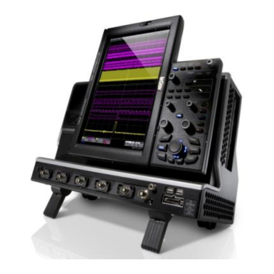
Summary of Contents for LeCroy WaveRunner 6Zi
-
Page 1: Getting Started
Getting Started M anual WaveRunner 6 Zi Oscilloscopes... - Page 2 WaveRunner 6 Zi Oscilloscopes February, 2011...
- Page 3 LeCroy shall not be responsible for any defect, damage, or failure caused by any of the following: a) attempted repairs or installations by personnel other than LeCroy representatives or b) improper connection to incompatible equipment, or c) for any damage or malfunction caused by the use of non-LeCroy supplies.
-
Page 4: Table Of Contents
Getting Started Manual TABLE OF CONTENTS Welcome ................ 2 WaveRunner 6 Zi Features .......... 2 Core Oscilloscope Functions ........2 Compatible Options and Accessories ......2 Reference ..............2 Support ............... 2 Thank You ..............3 Safety Requirements ..........3 Safety Symbols ............ - Page 5 WaveRunner 6 Zi Oscilloscopes Trigger Front Panel Controls ........21 Horizontal Front Panel Controls ....... 23 Vertical Front Panel Controls ........23 Math, Zoom, and Memory Indicators and Controls 24 The WavePilot Control Area and The SuperKnob ..25 Probe and Signal Connection Interfaces ....... 32 Probe and Signal Connection Interfaces Overview ..
- Page 6 Getting Started Manual Timebase Setup and Control ........54 Sampling Modes ............55 Sampling Modes Overview ........55 Selecting a Sampling Mode ........55 Single-shot Sampling Mode ........55 Basic Capture Technique .......... 55 Sequence Display Modes .......... 58 Sequence Mode Setup ..........59 Zooming Segments in Sequence Mode ....
- Page 7 WaveRunner 6 Zi Oscilloscopes Variable Gain ............69 Enabling Variable Gain ..........70 Channel Deskew ............70 Channel Deskew Setup ..........70 Trigger ................71 Trigger Overview ............71 Trigger Types ............71 Edge ................72 Width ................ 72 Pattern (Logic) ............72 Smart ................
- Page 8 Getting Started Manual Moving Traces from Grid to Grid ......92 Displays Containing Masks........92 Dual Display Grid Selection ........93 Persistence ..............94 Persistence Overview ..........94 Persistence Setup ............. 94 WaveStream Display Mode ........96 Adjusting Trace Intensity .......... 96 Zooming Waveforms ............
- Page 9 WaveRunner 6 Zi Oscilloscopes Standard Horizontal Parameters ......108 Selecting Measure Modes ........108 Help Markers ............108 Help Markers Setup ..........110 Measurement Parameter Analysis ......111 Measurement Parameter Analysis Overview ..111 Creating and Viewing a Histogram ......113 Single Parameter Histogram Setup ......
- Page 10 Getting Started Manual Search Modes ............140 Parameter Measurements ........141 Sampling Mode ............141 Customization Overview ..........142 Documenting Your Work Using LabNotebook .....144 LabNotebook Overivew .......... 144 LabNotebook ............145 Save/Recall..............149 Save/Recall Overview ..........149 Saving and Recalling Setups ........150 Saving Oscilloscope Setup(s)........
- Page 11 WaveRunner 6 Zi Specifications ......185 CERTIFICATIONS ............. 185 CE Declaration of Conformity......... 185 EMC Directive ............185 Low-Voltage Directive ..........186 UL and cUL.............. 187 Contact LeCroy for Support ........188 ® Windows License Agreement ....... 202 Index ................203 WR6Zi-GSM-E...
-
Page 12: Welcome
Getting Started Manual Welcome Thank you for purchasing a LeCroy product. We're certain you'll be pleased with the detailed features so unique to our instruments. This WaveRunner 6 Zi Online Help file may be accessed from your oscilloscope with the intention of Operator's Manual usage. Sections can be printed and the file itself can be saved to a USB memory device. -
Page 13: Thank You
WaveRunner 6 Zi Oscilloscopes Contact your nearest LeCroy customer service center or national distributor if anything is missing or damaged. If there is something missing or damaged, and you do not contact us immediately, we cannot be responsible for replacement. - Page 14 Getting Started Manual This symbol is used to denote the measurement ground connection. This symbol is used to denote a safety ground connection. On (Supply). This is the AC mains connect/disconnect switch at the back of the instrument (if provided). Off (Supply).
-
Page 15: Operating Environment
WaveRunner 6 Zi Oscilloscopes CAUTION The CAUTION sign indicates a potential hazard. It calls attention to a procedure, practice or condition which, if not followed, could possibly cause damage to equipment. If a CAUTION is indicated, do not proceed until its conditions are fully understood and met. WARNING The WARNING sign indicates a potential hazard. -
Page 16: Safety Certification
Getting Started Manual WARNING The oscilloscope must not be operated in explosive, dusty, or wet atmospheres. CAUTION Protect the oscilloscope's display touch screen from excessive impacts with foreign objects. CAUTION Do not exceed the maximum specified front panel terminal voltage ratings. -
Page 17: Cooling
WaveRunner 6 Zi Oscilloscopes Pollution Degree 2 refers to an operating environment where normally only dry non-conductive pollution occurs. Conductivity caused by temporary condensation should be expected. Protection Class 1 refers to grounded equipment, in which protection against electric shock is achieved by Basic Insulation and by means of a connection to the protective ground conductor in the building wiring. -
Page 18: Power Consumption
Getting Started Manual No manual voltage selection is required because the instrument automatically adapts to line voltage. Power Consumption Power Consumption (Nominal): 400 Watts (400 VA) Max Power Consumption (with all PC peripherals, active probes connected to 4 channels, and MSO active): 500 Watts (500 VA) Power consumption (in Standby Mode): 15 Watts Power and Ground Connections The instrument is provided with a 10A/250V 18AWG rated grounded... - Page 19 WaveRunner 6 Zi Oscilloscopes Always use the Power Switch or File → Shutdown command in the software to properly shut down your instrument. WR6Zi-GSM-E...
- Page 20 Getting Started Manual Never substitute this practice by pulling the instrument power cord from the socket or shutting down a connected power strip. CAUTION The outer conductors of the front panel BNC or ProBus terminals for all input channels are connected to the instrument’s chassis and therefore to the safety ground.
-
Page 21: Calibration
WaveRunner 6 Zi Oscilloscopes Changes can be made to the oscilloscope's original factory settings via the Power Options Properties menu in Windows under Control Panel → Power Options. A Windows Power Option named Standby provided control of only the oscilloscope’s computer subsystems (CPU, hard drive, etc.) and did not affect the other subsystems within the oscilloscope. -
Page 22: Abnormal Conditions
Getting Started Manual Avoid electrical shock hazard by unplugging the power cord from the AC outlet before cleaning. WARNING - Electrical Shock Hazard No operator serviceable parts inside. Do not remove covers. Refer servicing to qualified personnel. Abnormal Conditions Operate the instrument only as intended by the manufacturer. -
Page 23: Hardware
1. Power Button 4. Ground 7. Rotating 2. Channel Inputs Connector and Display Release 3. EXT Input and Probe Switch AUX Output Calibration Hook 8. Touch Screen connectors 5. USB Connections Stylus and LeCroy Bus Port 6. Front Panel WR6Zi-GSM-E... -
Page 24: Rotating And Tilting The Display
Getting Started Manual Rotating and Tilting the Display The display panel allows for Rotation and Tilting adjustments. These adjustments allow you to position your instrument with unmatched versatility. Rotate and Tilt your display using the following instructions: Note: Your oscilloscope should always be firmly planted on a solid supporting surface at all times. - Page 25 WaveRunner 6 Zi Oscilloscopes The user interface then adjusts its layout from landscape (horizontal) to portrait (vertical). This setup is ideal for viewing high-amplitude signals. The Rotating Display shown in portrait layout position. Reverse the process by grasping the now upper side of the display. Again, use your thumb to push upward on the release switch;...
- Page 26 Getting Started Manual Tilt the display by firmly grasping the far left side of the display and the far right side of the front panel. Use your wrists to forcibly tilt the display by pushing the upper-portions forward (to tilt upward) or the lower- portions backward (to tilt downward) until the desired positioning is reached.
-
Page 27: I/O Panel
The I/O Panel is located on the right side (facing) of the instrument as follows: Note: A LeCroy Bus (LBUS) connection is located on the Front Panel (on page 13). Numbered labels on the following I/O Panel image correspond with descriptions on the following table. -
Page 28: Back Panel
Back Panel The AC Power Plug is located on the back panel of your instrument. Note: The WaveRunner 6 Zi has a removable hard drive option. Contact your LeCroy representative for details using Contact LeCroy for Support (on page 188). WR6Zi-GSM-E... -
Page 29: Basic Controls
WaveRunner 6 Zi Oscilloscopes Basic Controls Hardware and Software Controls The following Basic Control topics cover the general usage of the hardware buttons located on the oscilloscope's front panel and the screen control interface elements of the software. Front Panel Controls Note: Many front panel controls directly correspond with screen layout controls. -
Page 30: Front Panel Groupings
Getting Started Manual Front Panel Groupings The front panel is divided into sections based on various functions. The following topics explain these sections in more detail. Miscellaneous Setup Controls and WaveStream Indicator This topmost section of the front panel provides the following functions: ... -
Page 31: Trigger Front Panel Controls
WaveRunner 6 Zi Oscilloscopes If Auto Setup is run when no channels are turned on, all channels are affected. When more than one channel is turned on, the first channel with a signal applied to it is automatically set up for edge triggering. - Page 32 Getting Started Manual READY and TRIG'D Indicators - The READY indicator is lit when the trigger is armed. TRIG'D is lit momentarily when a trigger occurs. A fast trigger rate causes the light to stay lit continuously. Setup - Press once to open the Trigger Setup... dialog. Corresponds with screen menu selection: Trigger →...
-
Page 33: Horizontal Front Panel Controls
WaveRunner 6 Zi Oscilloscopes Horizontal Front Panel Controls Note: Horizontal front panel controls can be applied to signals, Math, Zoom, or Memory traces. See Math, Zoom, and Memory Indicators and Controls (on page 24) for more information. Delay - Press to toggle between a zero horizontal delay value and the previous horizontal delay value. -
Page 34: Math, Zoom, And Memory Indicators And Controls
Getting Started Manual Channels - The channel buttons (1 - 4 and Digital) control both channel ON/OFF and which channel is active for the Vertical Offset and Volts/Div knobs controls. If a channel is OFF, pressing that channel button turns it on and makes it active. If a channel button is ON, pressing that channel button makes it active, and then pressing it a second time turns it OFF. -
Page 35: The Wavepilot Control Area And The Superknob
WaveRunner 6 Zi Oscilloscopes The WavePilot Control Area and The SuperKnob ILOT ONTROL REA AND UPER VERVIEW The WavePilot Control Area contains buttons that correspond to specific functions. These function buttons are used together with the SuperKnob to provide increased instrument control at your fingertips. The SuperKnob is a joystick-like knob in the center of the WavePilot Control Area used to make selections or provide specific values. - Page 36 Getting Started Manual Control values can be adjusted using the touch screen, a connected mouse, or by use of the SuperKnob. Turning the SuperKnob moves through available control values and, as indicated by the Help Flyout menu, pressing the SuperKnob provides Toggle Variable functionality; meaning, fine and coarse adjustments (if available for the particular control) may be selected for use.
- Page 37 WaveRunner 6 Zi Oscilloscopes Some models have Table and Zoom LED indicators along with Adjust. Others have only an Adjust LED with Zoom and Table buttons containing backlit LEDs. OOM AND ABLE UTTONS The Zoom and Table buttons may (or may not) provide additional control for a specific WavePilot funciton you have selected.
- Page 38 Getting Started Manual When no LED's surrounding the SuperKnob are lit, the cursors are in an Absolute or Off state. Using the SuperKnob with Cursors The SuperKnob joystick is used for cursor control while in Horizontal and Vertical states in the following manner: ...
- Page 39 WaveRunner 6 Zi Oscilloscopes Zoom and Table Buttons for Decode The Zoom and Table buttons are used as described in The WavePilot Control Area and The SuperKnob Overview (on page 25). Decode tables are shown beneath the main display area. When first pressing the WaveScan function button, the WaveScan dialog is shown with table data showing in a column to the left of the main display area.
- Page 40 Getting Started Manual Zoom and Table Buttons for History The Zoom and Table buttons are used as described in The WavePilot Control Area and The SuperKnob Overview (on page 25). OTEBOOK When first pressing the LabNotebook function button, the LabNotebook dialog is shown.
- Page 41 WaveRunner 6 Zi Oscilloscopes Zoom and Table Buttons for Spectrum Zoom and Table buttons are used as described in The WavePilot Control Area and The SuperKnob Overview (on page 25). In addition, a spectrum-specific Table control functionality Centers the Frequency of your displayed waveform when the SuperKnob is pressed based on the particular Frequency row you have selected from the Spectrum table displayed to the left of the main display area.
-
Page 42: Probe And Signal Connection Interfaces
Interfaces Probe and Signal Connection Interfaces Overview LeCroy oscilloscopes are equipped with a variety of connection interfaces to allow connection of cables directly to the oscilloscope channels, or to allow probe connections to the oscilloscope. When probes are connected, a probe interface is used to power the probe (as necessary),... -
Page 43: Probe Interfaces
169) topic for Auxiliary Output dialog details. Probe Interfaces Probe Interfaces Overview LeCroy oscilloscopes utilize one or more proprietary probe interfaces providing a complete measurement solution from probe tip to oscilloscope display. Compared to standard BNC and Probe Ring... - Page 44 LeCroy supports. A LeCroy Zi series oscilloscope showing the four sets of ProBus/ProLink probe interfaces. Zi oscilloscopes are compatible with all LeCroy probes. The following figure shows a typical channel setup dialog on a LeCroy oscilloscope containing both ProLink (Input A, Upper) and ProBus (Input B, Lower) interfaces.
-
Page 45: Probus Probe And Cable Connecting Interface
WaveRunner 6 Zi Oscilloscopes The channel dialog layout showing Input A's ProLink interface controls setup before connection. When a probe is connected, it is recognized and an additional tab with the probe model name is displayed to the right of the C1 tab. The channel dialog layout showing Input A's ProLink interface controls setup after connection. -
Page 46: Probes
50 Ω coupling or up to 1 GHz for 1 MΩ coupling (depending on the exact model purchase). Probes LeCroy offers a variety of passive and active probes for use with your X- Stream oscilloscope. Visit www.lecroy.com for specifications and ordering information. -
Page 47: Passive Probe Compensation
WaveRunner 6 Zi Oscilloscopes High Voltage Probes - These are active, single-ended probes designed to safely measure high voltages. They measure the voltage in reference to ground. Passive Probe Compensation Passive probes must be compensated to flatten overshoot. This is accomplished by means of a trimmer at the connector end of the probe. -
Page 48: Display Dashboard
Getting Started Manual Display Dashboard Display Dashboard Overview This section covers the various aspects of the user interface shown in the display of your instrument. Screen Layout, Groupings, and Controls The instrument's screen is divided into the following main sections: ... -
Page 49: Menu Bar
WaveRunner 6 Zi Oscilloscopes Menu Bar The top of the screen contains a menu bar of commonly used functions. Whenever you touch one of these buttons and make a selection from its drop-down menu, the dialog area at the bottom of the screen displays the corresponding dialog. -
Page 50: The Signal Display Grid
Getting Started Manual The Signal Display Grid The grid area is divided into 8 vertical divisions and 10 horizontal divisions just like any other oscilloscope. Set up the signal display area by touching Display → Display Setup... from the menu bar. The Display dialog offers a choice of grid combinations and can also set the grid intensity. - Page 51 WaveRunner 6 Zi Oscilloscopes The default setting (Time) is for delay readout (in seconds) and to move proportionately when the timebase knob is turned. If you want to set delay (Div) to a fixed position on the grid, and then have it stay fixed as the timebase changes, go to Utilities →...
-
Page 52: Signal Display Grid Pop-Up Menu
Getting Started Manual Signal Display Grid Pop-Up Menu On the Signal Display Grid, the Pop-up menu provides assistance while using the oscilloscope. Clicking on a waveform opens a pop-up menu. From this pop-up menu, you can perform the following functions: ... - Page 53 WaveRunner 6 Zi Oscilloscopes These indicators have a long and short form, respectively. The long and short forms of trace descriptor indicators. Besides channel traces, math and parameter measurement labels are also displayed. Labels are displayed only for traces that are turned on. Vertical and horizontal trace descriptor (labels) are displayed below the grid.
-
Page 54: Actions For Trace Buttons
Getting Started Manual Actions for Trace Buttons You can access the same functions as the ones produced when using the Signal Display Grid Pop-Up menu just by clicking a trace-descriptor label, which shows its corresponding dialog. From the respective dialog, you're able to access the same functions as Actions for Trace X buttons. - Page 55 WaveRunner 6 Zi Oscilloscopes If you are creating a label for the first time for this waveform, Label1 is displayed as default text when the Add label button is clicked. From this pop-up you can edit existing annotations, change the label placement on the waveform, add labels, remove labels, and toggle the visibility.
-
Page 56: Dialog Area
Getting Started Manual Precisely place the label by touching inside the Horizontal Pos. field and provide a horizontal value, using the pop-up numeric keypad. Add another label by touching the Add label button. Delete a label by selecting the label from the list, and then touching the Remove label button. - Page 57 WaveRunner 6 Zi Oscilloscopes This larger Pop-Up has categorical buttons along the left column along with labels (and sometimes descriptions) for the selectable entry values. Pop-Up Selector Control for values with varied types. NTRY ONTROLS Most controls can be touched once and you can then provide a value using an attached (or double-touch/click to use the Virtual, on-screen) keyboard.
- Page 58 Getting Started Manual OLDER ROWSING ONTROLS These controls allow for navigation to or from folders (on the hard drive or memory device) for retrieving or storing items such as waveforms, LabNotebook entries, to name a few. Folder/File Browsing recall waveform controls. Note: The instrument's hard disk is partitioned into drive C: and drive D:.
- Page 59 WaveRunner 6 Zi Oscilloscopes An example of Flyout Menu Controls is seen in the Setup front panel button. Setup Flyout Menu control. RECISION NTRY ONTROLS Certain fields requiring precise value entry assist you by having precision entry means. When these controls are selected, you can provide values as follows: Keyboard Touch inside a text entry control and you can manually type the value in...
- Page 60 Getting Started Manual Slider Bar Some models provide what is known as a Slider Bar along the bottom of the screen when a keyboard is attached to the instrument. The Slider Bar allows you to select your entered value by moving a horizontal slider (left to right provides low to high amounts).
-
Page 61: Actions For Trace Buttons
WaveRunner 6 Zi Oscilloscopes Actions for Trace Buttons Several dialogs contain common functions accessible from a row of buttons that can save you a step or two when using a particular function (instead of accessing the respective location from the menu bar or the Signal Display Grid Pop-Up Menu). -
Page 62: Message Bar
Getting Started Manual Another example is seen in the buttons appearing at the bottom of the Measure Px dialogs. The button may be selected in order to display the functions named on the buttons (sometimes labeled as Actions): Actions for Trace buttons on the Cx dialog. Using these buttons allow you to remain in the Measure dialog while setting up a Math trace on a parameter measurement. - Page 63 WaveRunner 6 Zi Oscilloscopes Whenever you turn on a channel, math, or memory trace using either the menu bar or trace descriptor label, the dialog at the bottom of the screen automatically switches to the vertical setup or math setup dialog for that selection.
-
Page 64: Timebase
Getting Started Manual Timebase Timebase Overview You can access Timebase settings using the front panel Horizontal controls, the Timebase → Horizontal Setup... on the menu bar, or by touching the Timebase trace descriptor label. The Timebase dialog is then shown. Timebase Setup and Control 1. -
Page 65: Sampling Modes
WaveRunner 6 Zi Oscilloscopes Sampling Modes Sampling Modes Overview Depending on your timebase, you can choose Single-shot Sampling Mode (below), also known as Real Time mode, Sequence Sampling Mode (on page 56), or RIS Sampling Mode (on page 63) mode sampling. Some instruments also offer Roll Mode (on page 64). - Page 66 Getting Started Manual This is 100% pre-trigger, and it allows you to see the waveform leading up to the point at which the trigger condition was met and the trigger occurred. (The instrument offers up to the maximum record length of points of pre-trigger information.) Post-trigger delay, on the other hand, allows you to sample the waveform starting at the equivalent of 10,000 divisions after the event occurred.
- Page 67 WaveRunner 6 Zi Oscilloscopes You can combine sequence mode with an advanced trigger to isolate a rare event, capture all instances over hours or days, and view/analyze each afterwards. You can use Sequence mode in remote operation to take full advantage of the instrument's high data-transfer capability.
-
Page 68: Sequence Display Modes
Getting Started Manual Sequence Display Modes The instrument gives you a choice of five ways to display your segments: Adjacent Waterfall (cascaded) Mosaic (tiled) Overlay WR6Zi-GSM-E... -
Page 69: Sequence Mode Setup
WaveRunner 6 Zi Oscilloscopes Perspective Note: some display modes have limitations on the number of segments that can be shown at one time. Sequence Mode Setup When setting up Sequence Mode, you define the number of fixed-size segments acquired in single-shot mode (see the instrument specifications for the limits). - Page 70 Getting Started Manual 2. Click the Sequence tab. 3. Under Acquisition Settings, touch inside the Num Segments data entry control and provide a value using your preferred input control method - for more information regarding the touch screen controls, refer to Dialog Area (on page 46). Note: The number of segments you choose to display can be less than the total number of segments in the waveform.
-
Page 71: Zooming Segments In Sequence Mode
WaveRunner 6 Zi Oscilloscopes Zooming Segments in Sequence Mode You can zoom individual segments easily using the Q front UICKZOOM panel button. When you zoom, the zoom traces default to Segment 1. Channel descriptors indicate the total number of segments acquired. Zoom descriptors indicate [Seg #] and #Segments in the Zoom. -
Page 72: Displaying An Individual Segment
Getting Started Manual 4. If you want to increase or decrease your horizontal or vertical zoom in small increments, touch the Var. checkbox to enable variable zooming. Now with each touch of the zoom control buttons, the degree of magnification changes by small increments. If you want to zoom in or out in large standard increments with each touch of the zoom control buttons, leave the Var. -
Page 73: Viewing Time Stamps
WaveRunner 6 Zi Oscilloscopes Viewing Time Stamps You can view time stamps for each segment. View Segment Time Stamps 1. Touch Timebase → Acquisition Status on the menu bar. Touch Vertical → Channel Status on the menu bar. 2. Touch the Trigger Time tab. 3. -
Page 74: Roll Mode
Getting Started Manual The process of acquiring these bins and satisfying the time constraint is a random one. The relative time between ADC sampling instants and the event trigger provides the necessary variation. The instrument requires multiple triggers to complete an acquisition. The number depends on the sample rate: the higher the sample rate, the more triggers are required. - Page 75 WaveRunner 6 Zi Oscilloscopes Note: If the processing time is greater than the acquire time, the data in memory gets overwritten. In this case, the instrument issues a Channel data is not continuous in ROLL mode!!! warning and rolling starts over again. WR6Zi-GSM-E...
-
Page 76: Vertical
Getting Started Manual Vertical Adjusting Sensitivity and Position You can make adjustments to both the sensitivity ad the positioning of displayed waveforms. Adjusting Sensitivity 1. Press the appropriate channel push button (channel 1, for example). Touch Vertical → Channel 1 Setup... from the menu bar. 2. -
Page 77: Coupling
Probe Attenuation Setting up Probe Attenuation LeCroy's ProBus system automatically senses probes and sets their attenuation for you. If you want to set the attenuation manually, 1. In the menu bar, touch Vertical, and then select a channel from the drop-down menu. -
Page 78: Bandwidth Limits
Getting Started Manual 2. Touch inside the Probe Atten. data entry control and provide a value using your preferred input control method - for more information regarding the touch screen controls, refer to Dialog Area (on page 46). 3. Now, touch a divide-by menu selection Touch Var (variable). -
Page 79: Linear And (Sinx)/X Interpolation
WaveRunner 6 Zi Oscilloscopes Linear and (SinX)/X Interpolation Linear interpolation, which inserts a straight line between sample points, is best used to reconstruct straight-edged signals such as square waves. (Sinx)/x interpolation, on the other hand, is suitable for reconstructing curved or irregular wave shapes, especially when the sample rate is 3 to 5 times the system bandwidth. -
Page 80: Enabling Variable Gain
Getting Started Manual However, when Variable Gain is enabled, you can increase or decrease the gain in increments as small as 0.1 mV/div, depending on the waveform scale. Enabling Variable Gain 1. Touch the descriptor label for the waveform whose gain you want to vary. -
Page 81: Trigger
WaveRunner 6 Zi Oscilloscopes Trigger Trigger Overview Triggering is the way an oscilloscope selects an exact moment in time on a signal to then be shown on the screen. If the pattern of a signal happens to be repetitive, a continuous waveform pattern is inherently visible on the display. -
Page 82: Edge
In addition, there are more sophisticated triggers for setting basic or complex conditions. These include Smart Triggers, Serial Trigger, Measurement Triggers, and MultiStage Triggers. Learn more and Contact LeCroy for Support (on page 188). Edge A simple trigger, Edge trigger is activated by basic waveform features or conditions such as positive or negative slope, and holdoff. - Page 83 WaveRunner 6 Zi Oscilloscopes INDOW A smart trigger occurs when a signal enters or exits a window defined by adjustable thresholds. NTERVAL While Glitch trigger performs over the width of a pulse, Interval trigger performs over the width of an interval - the signal duration (the period) separating two consecutive edges of the same polarity: positive to positive or negative to negative.
-
Page 84: Measurement
Getting Started Manual The Runt trigger occurs when a pulse crosses a first threshold line, but fails to cross a second threshold line before recrossing the first. Other defining conditions for this trigger are the edge (triggers on the slope opposite to that selected) and runt width. -
Page 85: Mulitstage
WaveRunner 6 Zi Oscilloscopes MulitStage Touching this MultiStage trigger type shows the additional MultiStage types on the dialog. Select from Cascaded, QualFirst, and Qualified as follows: ASCADED The Cascaded trigger allows you to define successive trigger Stages (referred to as Stage A, B, C, and D) as arm, trigger/arm, trigger/arm, trigger criteria, respectively. -
Page 86: Serial Trigger
Getting Started Manual State The State trigger is a level-qualified trigger which requires that the qualifying signal remain above or below a specified voltage level for a trigger to occur. For State trigger, you specify the time or number of events after the signal has gone above or below the voltage level when you want the trigger to occur. -
Page 87: Trigger Setup
WaveRunner 6 Zi Oscilloscopes The trigger location is shown by a marker under the grid. Post-trigger delay is indicated by a left-pointing arrow at the lower-left of the grid. The time value is given in the title line of the Timebase label at the lower-right of the grid. - Page 88 Getting Started Manual 1. Make your Type selection by touching the button corresponding to the desired trigger. 2. Touch inside the trigger Source control for your first Setup configuration and select a source on which to trigger. 3. If available, touch inside the Coupling control and select a coupling mode.
- Page 89 WaveRunner 6 Zi Oscilloscopes Coupling refers to the type of signal coupling at the input of the trigger circuit. Choices of trigger coupling vary by oscilloscope model. With DC coupling, all of the signal's frequency components are coupled to the trigger circuit for high-frequency bursts. 4.
- Page 90 The Amplitude and Range of the trigger level have limits as detailed in the datasheet specifications regularly maintained on www.lecroy.com. Touch inside the Level data entry control and provide a value using your preferred input control method - for more information regarding the touch screen controls, refer to Dialog Area (on page 46).
-
Page 91: Optimize For Hf
WaveRunner 6 Zi Oscilloscopes Some additional controls and dialogs for triggers that differ are provided in the following topics as examples. Optimize for HF The Optimize for HF checkbox can be used on an Edge trigger to reject high or low frequencies. The checkbox is marked by default;... -
Page 92: Width Condition Is
Getting Started Manual Width Condition is Width triggers (and other triggers equipped with conditional logic) have conditional logic settings as follows. Your Width Condition can be specified as Less Than, Greater Than, In Range and Out Of Range. In Range and Out Of Range conditions can be further set with Upper and Lower Values (for Limits). - Page 93 WaveRunner 6 Zi Oscilloscopes Now, click the corresponding control and provide a value. Use holdoff to obtain a stable trigger for repetitive, composite waveforms. For example, if the number or duration of sub-signals is known you can disable them by choosing an appropriate holdoff value. Qualified triggers operate using conditions similar to holdoff.
-
Page 94: Auxiliary Input Trigger
Getting Started Manual A trigger is generated when the condition is met after this number, counted from the last trigger. The count is restarted on each trigger. For example, if the event number is two, the trigger will occur on the third event. -
Page 95: Triggerscan
WaveRunner 6 Zi Oscilloscopes TriggerScan TriggerScan is a debugging tool (available for any trigger type) that helps you quickly find rare waveform glitches and anomalies. With TriggerScan, you can build a list of trigger setups to look for rare events and automatically sequence through each one. -
Page 96: Training Triggerscan
Getting Started Manual Training TriggerScan The TriggerScan Trainer inspects a currently acquired waveform and automatically builds a list of common trigger setups used to find rare events. PLEASE NOTE THE FOLLOWING: You must acquire and display at least 3 cycles of a signal before running the Trainer. -
Page 97: Starting Triggerscan
WaveRunner 6 Zi Oscilloscopes Starting TriggerScan After you have run the Trainer, the Trigger List displays a list of smart trigger setups. You can add or remove trigger setups. You can also update the selected smart trigger setup. Once you have made any changes to the Trigger List, you are ready to start scanning. -
Page 98: Saving Triggerscan Setups
Getting Started Manual PLEASE NOTE THE FOLLOWING: You can tune the dwell time that the oscilloscope waits before loading the next trigger setup using the Dwell Time data entry control. If you have Persistence display mode enabled, all trigger events are recorded on the display. -
Page 99: Display Setup
WaveRunner 6 Zi Oscilloscopes Channel traces are typically 8-bits of vertical data, whereas Math traces are 16-bits of vertical data. LeCroy grids consist of eight vertical divisions. When displaying channel traces on the grid, use of less than full-grid amplitude results in some reduced vertical resolution and accuracy. For instance, if a channel trace is displayed as two divisions high on a grid, the number of ADC bits utilized is... -
Page 100: Wr6Zi-Gsm-E
Getting Started Manual 2. Touch one of the Display combination buttons. PLEASE NOTE THE FOLLOWING: Small images label each Display combination button and indicate its corresponding grid configuration. Autogrid automatically adds or deletes grids as you select more or fewer waveforms to display. - Page 101 WaveRunner 6 Zi Oscilloscopes 4. Touch the Grid on top checkbox if you want to superimpose the grid over the waveform. Note: Depending on the grid intensity, some of your waveforms may be hidden from view when the grid is placed on top. To undo, simply uncheck Grid on top.
-
Page 102: Moving Traces From Grid To Grid
Getting Started Manual Touch inside the Num seg displayed control and enter a value, using the pop-up keypad. Touch inside the Starting at control and enter a value. Moving Traces from Grid to Grid You can move traces from grid to grid with the touch of a button. Moving a Channel or Math Trace 1. -
Page 103: Dual Display Grid Selection
WaveRunner 6 Zi Oscilloscopes Dual Display Grid Selection Make a dual grid display selection for showing on an external display (once properly connected to the I/O panel) by selecting Display → Display Setup..Numbered labels on this image correspond with the following steps. -
Page 104: Persistence
Getting Started Manual Persistence Persistence Overview The Persistence feature helps you display your waveform and reveal its idiosyncrasies or anomalies for a repetitive signal. Use Persistence to accumulate on-screen points from many acquisitions to see your signal change over time. The instrument persistence modes show the most frequent signal path in three-dimensional intensities of the same color, or graded in a spectrum of colors. - Page 105 WaveRunner 6 Zi Oscilloscopes Persistence Setup for Each Input Channel Individually 1. Touch the Per Trace button. 2. Touch one of the persistence mode buttons next to an input channel. To turn off persistence for an individual channel, touch the left- most persistence mode button next to the channel.
-
Page 106: Wavestream Display Mode
Getting Started Manual WaveStream Display Mode This fast viewing mode provides brightness-graded intensity with a decay time similar to the action of phosphor on an analog screen. WaveStream mode operates at up to 80 GS/s with an update rate of up to several thousand waveforms/second for better capture of higher frequency abnormal events. -
Page 107: Zooming Waveforms
WaveRunner 6 Zi Oscilloscopes Zooming Waveforms Zooming Waveforms Overview You can magnify a selected region of a waveform using the Zoom function. You can display up to four Zoom (Z1 - Z4) and eight Math Zoom traces (F1 - F8).You can zoom: ... -
Page 108: Previewing Zoomed Waveforms
Getting Started Manual Previewing Zoomed Waveforms When you zoom a waveform, a preview of the zoomed area is shown on the Preview section of the Zx dialog. Zooming a Single Channel The Zoom button appears as a standard button at the bottom of the channel Cx Vertical Adjust setup dialog for you to create a zoom trace of your input waveform. - Page 109 WaveRunner 6 Zi Oscilloscopes 4. If you want to increase or decrease your horizontal or vertical zoom in small increments, touch the Var. checkbox to enable variable zooming. Now with each touch of the zoom control buttons, the degree of magnification changes by a small increment.
-
Page 110: Touch-And-Drag Zooming
Getting Started Manual Vertical Position - Press to reset the vertical zoom position to zero. Turn to change the vertical position of the selected math or zoom trace. Vertical Ratio - Press to toggle between fixed and variable vertical zoom ratio adjustment. -
Page 111: Turning Off Zoom
WaveRunner 6 Zi Oscilloscopes Turning Off Zoom Turn off a Zoom by either pressing the front panel Zoom button again. On the corresponding Zoom dialog, touch the Trace On checkbox to remove the check mark and disable the zoom trace. WR6Zi-GSM-E... -
Page 112: Measuring With Cursors
Getting Started Manual Measuring with Cursors Measuring with Cursors Overview Cursors are important tools that aid you in measuring signal values. Cursors are markers - lines, cross-hairs, or arrows - that you can move around the grid or the waveform itself. Use cursors to make fast, accurate measurements and eliminate guesswork. -
Page 113: Cursors Setup
WaveRunner 6 Zi Oscilloscopes Abs+Delta Displays absolute and delta cursors together. Slope Displays the slope between cursors. If there are non–time-domain waveforms displayed, there will also be a menu offering choices of x-axis units: s or Hz, for example. Cursors Setup Quick Display At any time, you can change the display of cursor types (or turn them off) without invoking the Cursors Setup... -
Page 114: Setting Up Relative Cursors
Getting Started Manual 2. In the dialog area, touch the Cursors On check box to display them. 3. Touch the Horizontal Abs or Vertical Absmode button. 4. Touch inside the Position 1 data entry control and type in a value for the cursor. -
Page 115: Measurement Parameters
WaveRunner 6 Zi Oscilloscopes Measurement Parameters Measurement Parameters Overview Parameters are measurement tools that determine a wide range of waveform properties. Use them to automatically calculate many attributes of your waveform, like rise-time, rms voltage, and peak-to- peak voltage, for example. There are parameter modes for the amplitude and time domains, custom parameter groups, and parameters for pass and fail testing. -
Page 116: Parameter Setup
Performs math (addition, subtraction, multiplication, division) on parameters indicated on the Source1 and Source2 controls. Advanced Web Edit Selecting this type uses LeCroy's Processing Web for measurement setup. This feature, available with the XWEB option, allows you to chain practically unlimited math functions together for operation on your waveform measurements. - Page 117 WaveRunner 6 Zi Oscilloscopes 4. If you selected Measure On Waveforms, touch inside the Measure field and select a parameter from the pop-up menu. If you selected Math On Parameters, touch inside the Math Operator data entry field and select a math function from the pop-up menu.
-
Page 118: Measure Modes
Getting Started Manual 5. In the mini-dialog to the right of the main setup dialog, touch the Gate tab to narrow the span of measurement - as covered in the Measure Gate topic (available in the online help files). 6. Touch the Accept tab to define parameter values to be used in the measurement - as covered in the Qualified Parameters topic (available in the online help files). - Page 119 WaveRunner 6 Zi Oscilloscopes For the at level parameters, Help Markers make it easier to see where your waveform intersects the chosen level. This feature also displays the hysteresis band that you have set about that level. You also have the option, by means of an Always On checkbox, to leave the Help Markers displayed after you have closed the Help Markers setup dialog.
-
Page 120: Help Markers Setup
Getting Started Manual Standard Vertical Parameter Help Markers Help Markers Setup 1. Touch Measure → Measure Setup... on the menu bar. 2. Select a Measure Mode: Std Vertical, Std Horizontal, or My Measure. 3. Touch the Show All button (as follows) to display Help Markers for every parameter being measured on the displayed waveform (C2 in the previous examples). -
Page 121: Measurement Parameter Analysis
Measurement Parameter Analysis Measurement Parameter Analysis Overview LeCroy provides a variety of unique capabilities for advanced measurement parameter analysis. Most LeCroy oscilloscopes calculate measurements for all instances in the acquisition. This provides the ability to rapidly and thoroughly analyze a long memory acquisition and calculate thousands or millions of parameter values, or find anomalous measurements. - Page 122 Getting Started Manual math traces. A common usage for track is to observe the modulation of a signal, such as amplitude, frequency, or pulse width modulation. See Creating a Track View (on page 121). Trends provide a view of the measurement parameter over an extended period of time and over multiple acquisitions.
-
Page 123: Creating And Viewing A Histogram
WaveRunner 6 Zi Oscilloscopes Characteristic Track Trend Time Correlation to Other Data Monitors an No. Trend points are not Evolution in the evenly spaced in time and therefore cannot be used Frequency Domain for an FFT. Monitors the No. Track resets Evolution of a after every Measurement... -
Page 124: Single Parameter Histogram Setup
Getting Started Manual the bar height relates to the number of data points inside each interval/bin. Various histograms can be setup using Measure or Math dialogs. Thumbnail versions of Histograms are called Histicons. Also, Persistence can be applied to Histograms. PLEASE NOTE THE FOLLOWING: 1. - Page 125 WaveRunner 6 Zi Oscilloscopes Using the Px Buttons on the Measure Dialog - After directly touching a Px button on the Measure dialog, the Select Measurement pop-up is shown. The Select Measurement pop-up. Using a Corresponding Px Tab/Dialog - After directly accessing a corresponding Px dialog, touch the Measure control and the Select Measurement pop-up is shown.
- Page 126 Getting Started Manual 3. Touch the Histogram button at the bottom of the dialog. After touching this button, the Math selection for Histogram pop-up is shown. Select the desired Math Trace in which to store the results. Touch the Close button when you are finished. Touch the trace descriptor label for the math trace just created for the results, and then touch the Histogram tab to access its right-hand dialog.
- Page 127 WaveRunner 6 Zi Oscilloscopes 4. Instead of using the Find Center and Width button, you can provide specific Center and Width values using their respective controls and providing values using the pop-up numeric keypad. INGLE ARAMETER ISTOGRAM ETUP SING Access the main Math dialog by selecting Math → Math Setup... on the menu bar.
-
Page 128: Viewing Thumbnail Histograms (Histicons)
Getting Started Manual Regardless of how you performed the previously described initial steps, at this point access your corresponding Fx dialog if you want to change other setup items as follows: You can modify the source of your waveform used on a Math trace using the source (Source 1) control. -
Page 129: Persistence Histogram
WaveRunner 6 Zi Oscilloscopes 1. On the menu bar, touch Measure, then one of the Measure Mode buttons: Std Vertical, Std Horizontal, or My Measure. 2. Touch the Histicons checkbox to display thumbnail histograms below the selected parameters. Note: For measurements set up in My Measure, you can quickly display an enlarged histogram of a thumbnail histogram by touching the Histicon you want to enlarge. -
Page 130: Persistence Trace Range
Getting Started Manual 4. Touch the Phistogram tab to access its right-hand dialog. Now, touch the Slice Direction control and select Horizontal or Vertical slice from the pop-up. 5. Touch inside the Slice Center field and enter a value using the pop-up keypad. -
Page 131: Creating A Track View
WaveRunner 6 Zi Oscilloscopes The Trend is then shown along with its respective trace descriptor label for the selected math function. 6. Touch the newly displayed Trend math function trace label to change settings on the Trend dialog (located on the Trend tab at the lower-right side of the screen). -
Page 132: Pass-Fail Parameter Testing
Getting Started Manual Now, from the Math selection for Track menu, select a math function location (Fx) on which to store the Track display. The Track is then shown along with its respective trace descriptor label for the selected math function. 6. -
Page 133: Testing And Enabling Pass/Fail Conditions
WaveRunner 6 Zi Oscilloscopes When you have each of the Qx dialogs configured and enabled as desired, you can then begin your testing and turn them all on or off using the Testing checkbox on the main Pass/Fail dialog. You can also specify Actions for all or some of your conditions using the Actions dialog. -
Page 134: Pass/Fail Setup On Qx Dialogs
Getting Started Manual When you have each of the Qx dialogs configured and enabled as desired, you can then begin your testing and turn them all on or off using the Testing checkbox on the main Pass/Fail dialog. Your test data is shown on the Table display area shown in the previous screen-shot. - Page 135 WaveRunner 6 Zi Oscilloscopes Select the desired condition. Note: Right hand dialogs back on the corresponding Qx dialog vary based on the Pass/Fail condition selected. The following sections cover the right hand dialogs for Bool identity and Param and Dual Param Compare. The Mask test condition is covered in Mask Testing (on page 134).
- Page 136 Getting Started Manual 2. Touch inside the Condition field on the ParamCompare part of the dialog and select a math operator from the pop-up menu. 3. Touch inside the Limit field and enter a value using the pop-up numeric keypad. The value entered acquires the dimensions corresponding to the parameters being tested.
- Page 137 WaveRunner 6 Zi Oscilloscopes Setups are conveniently shown in the Summary box of the Qx dialog as follows (shown on the Dual Param Compare right-hand dialog): 1. Touch Analysis → Pass/Fail Setup... from the menu bar. 2. Touch one of the Qx tabs and a setup dialog for the position is shown.
-
Page 138: The Actions Dialog
Getting Started Manual 7. Touch inside the Condition field on the ParamCompare part of the dialog and select a math operator from the pop-up menu. 8. Touch inside the Limit field and enter a value, using the pop-up numeric keypad. This value takes the dimension of the parameter that you are testing. - Page 139 WaveRunner 6 Zi Oscilloscopes You can also decide the actions to occur upon your waveforms' passing or failing, by selecting one or all of the following: stop audible alarm print image of display emit pulse (if available) ...
- Page 140 Getting Started Manual 4. Touch the Summary View checkbox to enable a line of text (as follows) showing a concise status of the last waveform and keeping a running count of how many sweeps have passed. 5. Touch inside the Pass If control, and select a Boolean condition from the choices shown.
-
Page 141: Math
WaveRunner 6 Zi Oscilloscopes Math Math Traces and Functions Overview LeCroy offers a deep toolset of math functions always growing and changing to provide superior functionality. Note: To find out which math tools are available in each optional package or for any detailed explanations about specific functionality, it's... -
Page 142: Math Setup
Getting Started Manual Math Setup Access the main Math dialog by selecting Math → Math Setup... on the menu bar. There are two ways to select your math operator during setup. They only differ in the order of the steps. ... - Page 143 WaveRunner 6 Zi Oscilloscopes Regardless of how you performed the previously described initial steps, at this point access your corresponding Fx dialog if you want to change other setup items as follows: You can modify the source of your waveform used on a Math trace using the source (Source 1) control.
-
Page 144: Mask Testing
Getting Started Manual Mask Testing Users may load or create a pixel-based mask on the display grid using a variety of methods. Test conditions can be set, and a pass/fail result returned based on whether the condition was found to be true or false. The source of the mask is always a trace (Channel, Zoom, Math waveform, etc.). - Page 145 WaveRunner 6 Zi Oscilloscopes Now, the Q1 dialog is shown and shows the Mask test condition selected. If you touch the Q1 tab, the Q1 dialog is shown. Touching the Condition control shows the same pop-up where you can select the Mask test Pass Fail Condition.
-
Page 146: Quick Access To Pass/Fail Setup Dialogs
Getting Started Manual Quick Access to Pass/Fail Setup Dialogs You can quickly gain access to the main Pass/Fail dialog, a (Qx) setup dialog, or the Actions dialog, by touching one of the following respective sections below the grid display. Removing a Mask from the Display Quickly remove a mask by accessing the Qx dialog. -
Page 147: Right-Hand Dialogs
WaveRunner 6 Zi Oscilloscopes Masks that you create from your waveform can be confined to just a portion of the trace by use of a measure gate. Refer to the Measure Gate online help topic for more information on how this feature works. Right-Hand Dialogs ... - Page 148 Getting Started Manual On the Gate right-hand dialog, you can enter values in the Start and Stop fields to constrain the mask to a portion of the waveform. Or, you can simply touch and drag the Gate posts, which initially are placed at the extreme left and right ends of the grid.
-
Page 149: Wavescan Overview
WaveRunner 6 Zi Oscilloscopes WaveScan Overview WaveScan enables you to search for unusual events in a single capture, or to scan for an event in many acquisitions over a long period of time. You can select from more than 20 search modes (frequency, rise time, runt, duty cycle, etc.), apply a search condition (slope, level, threshold, hysteresis), and begin scanning in a post-acquisition environment. -
Page 150: Signal Views
Getting Started Manual Signal Views WaveScan provides distinct views of your signal: Source (Channel View)view highlights all occurrences of edges that meet your criteria. Scan Overlay places all captured edges one on top of the other in a separate grid. You can apply monochromatic persistence in this view. -
Page 151: Parameter Measurements
WaveRunner 6 Zi Oscilloscopes Bus Pattern – Searches from 2 to 64 bits; enhances MSO search capabilities. Parameter Measurements Besides parameter measurements made during acquisition, post- acquisition measurements can also be made. The number of parameters available depends on the options loaded on your instrument. Measurements are made only on the events defined by your filter (search criteria). -
Page 152: Customization Overview
Getting Started Manual Customization Overview The instrument provides powerful capability to add your own parameters, functions, display algorithms, or other routines to the oscilloscope user interface without having to leave the instrument application environment. You can customize the instrument to your needs by using the power of programs such as Excel™, Mathcad™, and MATLAB™, or by scripting in VBS. - Page 153 WaveRunner 6 Zi Oscilloscopes You can do additional processing on the result by applying either standard instrument parameters, functions, etc. to the returned result, or even more powerfully, adding chained customized functions. For example, you can do an Excel calculation on a result with a MATLAB function applied to it.
-
Page 154: Documenting Your Work Using Labnotebook
Documenting Your Work Using LabNotebook LabNotebook Overivew LeCroy's LabNotebook feature extends the documentation capabilities of your oscilloscope. It allows you to create an annotated notebook entry containing all displayed waveforms, the setup of the DSO, and user- supplied annotations. The notebook entry can then be converted to hardcopy format - .pdf, .rtf, or .html - and printed or e-mailed. -
Page 155: Labnotebook
WaveRunner 6 Zi Oscilloscopes LabNotebook When LabNotebook is accessed by File → LabNotebook on the menu bar, the main LabNotebook dialog is shown by default. This dialog is where you can store and create LabNotebook entries. You also can View, Create, E-Mail, and select an output format for your reports. - Page 156 Getting Started Manual Touch inside the Title control and provide a value using your preferred input control method - for more information regarding the touch screen controls, refer to Dialog Area (on page 46). If desired, touch inside the Description field, provide information and touch Save.
- Page 157 WaveRunner 6 Zi Oscilloscopes Cumulative Measurements - Any measurements on when the Lab Notebook entry is created are not saved individually in the database (other than being embedded in the hardcopy image). This means that when flashback is used, the measurements are recomputed using the recalled waveform data.
- Page 158 Getting Started Manual 5. Use the View, Create Report, and E-Mail buttons as desired. The More Actions button shows the Specific Entry dialog for the entry selected on the My Notebook Entries list. Using this dialog is explained in Managing Notebook Entry Data in the online help. 6.
-
Page 159: Save/Recall
WaveRunner 6 Zi Oscilloscopes Save/Recall Save/Recall Overview The Save/Recall section allows for storage and retrieval of Waveforms, Table Data, and Instrument Setups. It even provides Disk Utilities for arranging the file/folder structure on your instrument's hard drive. Directly access each Save/Recall dialog (Waveform, Table, Setups, and Disk Utilities on the File menu on the menu bar. -
Page 160: Saving And Recalling Setups
Getting Started Manual Saving and Recalling Setups The Save/Recall Setup dialogs allow for quick saving and recalling of up to six oscilloscope panel settings internally on your instrument. If desired, you can also save and recall your oscilloscope panel settings as an .lss file to a specific hard disk location, a network location, or USB drive. -
Page 161: Recalling Default Settings
WaveRunner 6 Zi Oscilloscopes ECALLING ETUP NTERNALLY ON NSTRUMENT Recall your settings located internally on your instrument by touching inside one of the six Recall buttons on the Recall From Internal Setup... part of the screen. Each Recall button is labeled with a corresponding setup storage slot. If a setup is stored, SetupX is shown along with the date/time of the save, otherwise, the slot is labeled Empty. -
Page 162: Saving And Recalling Waveforms
Getting Started Manual Saving and Recalling Waveforms Saving Waveforms The Save Waveform dialog is used to save displayed waveforms to either a memory trace or to text or binary file formats. Access the Save Waveform dialog by either selecting File → Save Waveform from the menu bar or clicking the Save Waveform button on the main Save/Recall dialog. - Page 163 5. If you are saving to a file, touch the Data Format control and select a format type. Binary - saves the file to LeCroy's binary file format. This format is documented in various Remote Control Manuals for LeCroy Oscilloscopes. Selecting Binary results in the smallest possible file size, and is recommended when recalling waveforms to LeCroy instruments.
- Page 164 Getting Started Manual Depending on your selection, you may need to touch the SubFormat control and select a subformat. Word - Available when selecting the Binary format, specifies the samples in the output file are represented with 16 bits. Always use this option unless Byte mode is pre.
-
Page 165: Recalling Waveforms
WaveRunner 6 Zi Oscilloscopes 7. Touch the Browse button next to the Save file in directory control and navigate to the location where you want the file saved. The file name is assigned automatically and is shown under the control. 8. - Page 166 Getting Started Manual 6. Touch inside the Recall files from directory data entry control and provide the path. You can also touch the Browse button and navigate to the file. Touch inside the Next file will be recalled from data entry control and provide the path or, touch the Browse button to navigate to the file.
-
Page 167: Utilities
WaveRunner 6 Zi Oscilloscopes Utilities Utilities Setup Utilities Overview Access Utilities by touching Utilities → Utilities Setup... on the menu bar. A variety of settings can be made on your oscilloscope using the Utilities. Utilities settings are divided into three main sections: Utilities, Disk Utilities, and Preferences. - Page 168 The Service button is a section of the application reserved for qualified LeCroy personnel. When touched, an access code pop-up is shown enabling LeCroy technicians access to various service dialogs inside the oscilloscope software.
-
Page 169: Status
PTIONS New software options can be added after purchasing a code and then enabling the option on the oscilloscope. Call LeCroy Customer Support to place an order and receive the code. Note: For more information about LeCroy Software Options, Contact LeCroy for Support (on page 188). - Page 170 GPIB is an option that either requires a GPIB card to be installed in an open card slot on your oscilloscope or the use of an external USB to GPIB LeCroy accessory. For more information about LeCroy Accessories, Contact LeCroy for Support (on page 188).
-
Page 171: Printing And Hardcopy Functions
WaveRunner 6 Zi Oscilloscopes Note: Your instrument allows you to restrict remote control access to certain clients. To restrict access, under Security, touch the Yes button and enter the IP addresses or domain name server names you want to restrict separated by a comma. ONFIGURING THE EMOTE ONTROL... - Page 172 Getting Started Manual RINTER ETUP 1. Touch File → Print Setup... on the menu bar. The Utilities Hardcopy dialog opens. Press the P front panel button. Then, touch the Print Setup... RINT button on the Print flyout menu. Touch Utilities → Utilities Setup... and click the Hardcopy tab. 2.
- Page 173 WaveRunner 6 Zi Oscilloscopes Choose Grid Area Only if you do not need to print the dialog area and you only want to show the waveforms and grids. Choose DSO window if you want to print the dialogs with the waveforms and grids.
- Page 174 Getting Started Manual On the Hardcopy dialog, touch the Print Now button. Note: The instrument uses the Print settings on the Hardcopy dialog to print the screen image. So, you can either print from File → Print or from Utilities → Utilities Setup...
- Page 175 WaveRunner 6 Zi Oscilloscopes Note: Once you have configured your Clipboard settings from the Hardcopy dialog (using the next procedure), you can touch the P RINT front panel button and touch Save Screen To Clipboard on the Print flyout menu. The instrument automatically uses the additional clipboard settings to save the screen image to the clipboard.
- Page 176 Getting Started Manual PLEASE NOTE THE FOLLOWING: The instrument's hard disk is partitioned into drive C: and drive D:. Drive C: contains the Windows operating system and the instrument application software. Drive D: is intended for data files. Once you have configured your Clipboard settings from the Hardcopy dialog (using the next procedure), you can touch the front panel button and touch Save Screen To File on the RINT...
- Page 177 WaveRunner 6 Zi Oscilloscopes Choose DSO window if you want to print the dialogs with the waveforms and grids. Choose Full Screen if you want to print the entire screen. 6. Touch the Print Now button. MAIL The E-mail selection on the Hardcopy tab gives you the option to e-mail your screen images, using either the MAPI or SMTP protocols.
- Page 178 Getting Started Manual 2. Touch the Colors control and choose Standard to print the screen as it appears, Print to print the waveforms on a white background, or Black & White to print the waveforms in black & white. Note: Choosing Print colors saves printer toner or ink (when you eventually do print from the file).
-
Page 179: Aux Output
WaveRunner 6 Zi Oscilloscopes Aux Output The Aux Output dialog allows you to specify Auxiliary and Calibration Output details. 1. If you want a specialized output, touch one of the following buttons under Use Auxiliary Output For: Square Wave, Trigger Enabled, Trigger Out, Pass/Fail, or Off. - Page 180 Pass/Fail - Allows you to set a pulse duration (durations vary based on your specific model, refer to datasheet specifications at www.lecroy.com for details); generates a pulse when pass/fail testing is active and conditions are met. Fast Edge - Some models provide this signal output used to deskew multiple channels.
-
Page 181: Date And Time
Square Wave - You can set a Frequency value (frequency ranges vary based on your specific model, refer to datasheet specifications at www.lecroy.com for details). DC Level - This is a reference level. Off - This function turns off the Calibration Output signal. -
Page 182: Options
Options The Options dialog is used to add or remove software options. Contact LeCroy for more information using Contact LeCroy for Support (on page 188), or visit our Website at www.lecroy.com/options. This dialog also shows your ScopeID and Serial #. - Page 183 WaveRunner 6 Zi Oscilloscopes Access the Disk Utilities dialog by selecting Utilities → Disk Utilities from the menu bar. 1. Delete a single file by first touching the Delete button on the dialog (just to make sure it's selected). Now, touch inside the Current folder data entry control and provide the path to the folder containing the file for deletion.
-
Page 184: Preferences
Getting Started Manual Now, touch the Create Folder button. Note: Disk Space data for Size, Free, and File(s) is available on the far right of the dialog for convenience. Preferences Preference Setup Overview A variety of customizable preferences can be set on your instrument. Access Preferences by touching Utilities →... -
Page 185: Acquisition
WaveRunner 6 Zi Oscilloscopes 2. You can choose to have your instrument automatically re-calibrate itself whenever there is a significant change in ambient temperature by marking the Enable checkbox on the Automatic Calibration section of the dialog. Note: If you do not enable this option, the oscilloscope re- calibrates only at startup and whenever you make a change to certain operating conditions. - Page 186 Getting Started Manual As you change the gain, this control allows you to either keep the vertical offset level indicator stationary (when Div is selected) or to have it move with the actual voltage level (when Volts is selected). The advantage of selecting Div is that the waveform remains on the grid as you increase the gain;...
-
Page 187: E-Mail
WaveRunner 6 Zi Oscilloscopes This preference clears the trigger counter each time the oscilloscope issues an arm acquisition command and applies when you have set a trigger Holdoff condition in the Trigger dialog in either time or events: The default condition of this control is off (unchecked). CQUISITION TATUS For each general category of oscilloscope operation, you can view a... - Page 188 Getting Started Manual MAPI (Messaging Application Programming Interface) is the Microsoft interface specification that allows different messaging and workgroup applications (including e-mail, voice mail, and fax) to work through a single client, such as the Exchange client . MAPI uses the default Windows e-mail application.
-
Page 189: Color
WaveRunner 6 Zi Oscilloscopes Color You can customize the Colors used for Channels, Math, and Memory traces both when shown on your instrument and when used in print output. Note: These color settings match a waveform on the grid display (both on-screen and printed) and show consistently on corresponding dialogs, tables, and trace descriptor labels. -
Page 190: Miscellaneous
Numbered sections on this dialog correspond with the following explanations. 1. You can add the LeCroy Logo to hardcopies of your grid display waveforms by marking the Print LeCroy Logo When Printing Grid Area Only checkbox on the Hardcopy section of the dialog. - Page 191 WaveRunner 6 Zi Oscilloscopes LeCroy provides you with an Acronis recovery application and a backup image in an extra partition on the instrument’s hard drive. PLEASE NOTE THE FOLLOWING: The recovery process produces a replica of the operating system and oscilloscope application software at the current revision levels when the oscilloscope was manufactured.
- Page 192 Getting Started Manual LeCroy provides you with a recovery application and a backup image in an extra partition on the instrument’s hard drive. The recovery process is easy to perform, using the Recovery Wizard. After the recovery procedure is done, you must activate Windows, either by Internet connection to Microsoft’s Web site or by telephone.
- Page 193 WaveRunner 6 Zi Oscilloscopes 10. On the Partition or Disk to Restore page, select SYSTEM (C:) as the source and click Next. 11. On the Restored Partition Type page, select Active and click Next. Note: If a window appears asking if you want to buy Acronis products, click Do not show this message again and click OK.
-
Page 194: Restarting The Application
Getting Started Manual Note: A Windows Security window may be displayed indicating that Windows can't verify the publisher of this driver software. Choose Install this driver software anyway and then click Install. 23. When the X-Stream installation is completed, reboot the oscilloscope. -
Page 195: Reference
Note: Specifications are subject to change without notice. Please refer to the LeCroy website at www.lecroy.com or the online help on your LeCroy oscilloscope for detailed specification information. CERTIFICATIONS CE Compliant, UL, and cUL Listed CE Declaration of Conformity The oscilloscope meets requirements of EMC Directive 2004/108/EEC for Electromagnetic Compatibility and Low Voltage Directive 2006/95/EEC for Product Safety. -
Page 196: Low-Voltage Directive
Getting Started Manual EN 61000-4-5:2006** Surges. (1 kV AC Mains, L-N, L-PE, N-PE) EN 61000-4-6:2007** RF Conducted Electromagnetic Field. (3 Vrms, 0.15 MHz - 80 MHz) EN 61000-4-11:2004† Mains Dips and Interruptions. (1 cycle voltage dip, 100% short interruption) * In order to conform to Radiated Emissions standards, use properly shielded cables on all I/O terminals. -
Page 197: Ul And Cul
WaveRunner 6 Zi Oscilloscopes Protection Class I (Provided with terminal for protective ground). UL and cUL The oscilloscope is UL and cUL listed and conforms to the following standards: UL Standard: UL 61010-1 2nd Edition. Canadian Standard: CSA-C22.2 No. 61010-1-04. WR6Zi-GSM-E... -
Page 198: Contact Lecroy For Support
You can also find contact information for our offices on the LeCroy Web sites shown for the following regions: Contact Your Local LeCroy Office for Sales and Technical Assistance... - Page 199 WaveRunner 6 Zi Oscilloscopes Contact Your Local LeCroy Office for Sales and Technical Assistance psgsupport@lecroy.com Web Site: www.lecroy.com Korea - Seoul China LeCroy Korea LeCroy Corporation Beijing Office and Service Center 10th fl.Ildong Bldg. Rm. 2001 - Office; Rm. 2002 -...
- Page 200 Getting Started Manual Contact Your Local LeCroy Office for Sales and Technical Assistance No. 2, Chien-8th Road, 3-11-5, Midori-cho, Fuchu-Shi Chung-Ho City, Tokyo, 183-0006 Taipei Hsien, Japan Taiwan, R.O.C. Phone (Sales and Support): ++ 81 4 2402 9400 Phone (Sales and Support): ++...
- Page 201 1. GRANT OF LICENSE. 1.1. License Grant. Subject to the terms and conditions of this EULA and payment of all applicable fees, LeCroy grants to you a nonexclusive, nontransferable license (the “License”) to: (a) operate the Software Product as provided or installed, in object...
- Page 202 (or other similar designation) the License will not take effect, and you will have no right to use or access the Software Product unless you are properly licensed to use a product identified by LeCroy as being eligible for the upgrade ("Underlying Product"). A Software Product labeled as an "upgrade"...
- Page 203 WaveRunner 6 Zi Oscilloscopes 1.3. Limitations. Except as specifically permitted in this EULA, you will not directly or indirectly (a) use any Confidential Information to create any software or documentation that is similar to any of the Software Product or Documentation; (b) encumber, transfer, rent, lease, time-share or use the Software Product in any service bureau arrangement;...
- Page 204 Getting Started Manual to you or has not been provided by LeCroy within a reasonable time after a written request by you to LeCroy to provide such information; (D) the information gained is not used for any purpose other than the Permitted Objective and is not disclosed to any other person except as may be necessary to achieve the Permitted Objective;...
- Page 205 "applets" embodied in or incorporated into the Software Product, collectively, "Content"), and all Derivatives, and any copies thereof are owned by LeCroy and/or its licensors or third-party suppliers, and is protected by applicable copyright or other intellectual property laws and treaties. You will not take any action inconsistent with such title and ownership.
- Page 206 Documentation) and other proprietary information of LeCroy; and any business, marketing or technical information disclosed by LeCroy, or its representatives, or you in relation to this EULA, and either (i) disclosed in writing and marked as confidential at the...
- Page 207 WaveRunner 6 Zi Oscilloscopes time of disclosure or (ii) disclosed in any other manner such that a reasonable person would understand the nature and confidentiality of the information. Confidential Information does not include information (A) already in the possession of the receiving party without an obligation of confidentiality to the disclosing party, (B) hereafter rightfully furnished to the receiving party by a third party without a breach of any separate...
- Page 208 DFARS §227.7202. The use of the Software Product or Documentation by the Government constitutes acknowledgment of LeCroy’s proprietary rights in the Software Product and Documentation. Manufacturer is LeCroy Corporation, 700 Chestnut Ridge Road, Chestnut Ridge, NY 10977 USA.
- Page 209 IMPLIED FROM ANY COURSE OF DEALING OR USAGE OF TRADE. YOU ACKNOWLEDGE THAT NO WARRANTIES HAVE BEEN MADE TO YOU BY OR ON BEHALF OF LECROY OR OTHERWISE FORM THE BASIS FOR THE BARGAIN BETWEEN THE PARTIES. 7.2. Limitation of Liability. LECROY’S LIABILITY FOR DAMAGES FOR...
- Page 210 No provision of, right, power or privilege under this EULA will be deemed to have been waived by any act, delay, omission or acquiescence by LeCroy, its agents, or employees, but only by an instrument in writing signed by an authorized officer of LeCroy.
- Page 211 LeCroy. In the case of any permitted assignment or transfer of or under this EULA, this EULA or the...
-
Page 212: Windows License Agreement
Getting Started Manual ® Windows License Agreement LeCroy's agreement with Microsoft prohibits users from running software on LeCroy X-Stream oscilloscopes that is not relevant to measuring, analyzing, or documenting waveforms. WR6Zi-GSM-E... -
Page 213: Index
WaveRunner 6 Zi Oscilloscopes Index Condition-Based Right-Hand Dialogs, 124 cooling, 7 abnormal conditions, 12 coupling, 67 Absolute, 102 Coupling, 78 ac power source, 7 Create a Folder, 172 Acquisition, 174 cursors actions, 127 icons, 101 Actions for Trace Buttons, 44 setup, 102 Annotating Traces, 44 Cursors, 27, 103... - Page 214 Getting Started Manual Display Overview, 87 histograms Displaying an Individual creating and viewing, 112 Segment, 62 History, 29 Displays Containing Masks, 91 holdoff, 81 Dual Display Grid Selection, 92 Horizontal Front Panel Controls, E-Mail, 176 I/O Panel, 17 Intensity knob, 95 intensity of grid, 89 file name numbering, 151 intensity of trace, 90...
- Page 215 WaveRunner 6 Zi Oscilloscopes Measurement Parameter Pass/Fail Condition Setup, 123 Analysis Overview, 110 Pass/Fail Parameter Testing Measurement Parameters Overview, 121 Overview, 104 pass/fail testing Measuring with Cursors actions, 127 Overview, 101 Pass/Fail Testing Setup, 128 Menu Bar, 39 Passive Probe Compensation, 37 Message Bar, 52 performance optimization, 174 Miscellaneous, 179...
- Page 216 Getting Started Manual Recalling Setup(s) Directly from Saving Waveforms, 151 a File, 150 Screen Layout, Groupings, and Recalling Setup(s) Internally on Controls, 38 Your Instrument, 150 Search Modes, 139 Recalling Waveforms, 154 segments remote: configuring, 158 displaying, 62 Removing a Mask from the Send Test Mail, 177 Display, 135 sensitivity and position:...
- Page 217 WaveRunner 6 Zi Oscilloscopes Starting TriggerScan, 86 TriggerScan, 84 status of scope, 158 Turning, 104 Turning on Channels and Traces, Type, 78 technical support, 187 Testing and Enabling Pass/Fail Conditions, 122 The Quick Access Toolbar, 39 utilities The Signal Display Grid, 40 acquisition status, 176 The WavePilot Control Area and audio feedback, 173...
- Page 218 Getting Started Manual Utilities Overview, 156 WaveScan Overview, 138 WaveStream, 95 Width, 81 Windows operating system, 183 variable gain, 69 Vertical Front Panel Controls, 23 view aux in, 83 Zooming Segments in Sequence Mode, 61 Zooming Waveforms Overview, waveform position, 66 WaveML data format, 153 WavePro, 184 WaveScan, 29...
- Page 219 Thank you for purchasing a WaveRunner 6 Zi oscilloscope.
Need help?
Do you have a question about the WaveRunner 6Zi and is the answer not in the manual?
Questions and answers