Table of Contents
Advertisement
Quick Links
Advertisement
Table of Contents

Related Manuals for DFI COM331-B


Summary of Contents for DFI COM331-B
- Page 1 COM331-B System Board User’s Manual A20700205...
-
Page 2: Copyright
Copyright This publication contains information that is protected by copyright. No part of it may be reproduced in any form or by any means or used to make any transfor- mation/adaptation without the prior written permission from the copyright hold- ers. -
Page 3: Fcc And Doc Statement On Class B
FCC and DOC Statement on Class B This equipment has been tested and found to comply with the limits for a Class B digital device, pursuant to Part 15 of the FCC rules. These limits are designed to provide reasonable protection against harmful interference when the equipment is operated in a residential installation. -
Page 4: Table Of Contents
Table of Contents ................... 2 Copyright ..................2 Trademarks ..........3 FCC and DOC Statement on Class B ................6 About this Manual ..................6 Warranty ............. 7 Static Electricity Precautions Safety Measures ................. 7 About the Package ................8 Before Using the System Board ............ - Page 5 ..............31 Internal I/O Connectors S/PDIF Connector ..............31 LVDS LCD Panel Connector and LCD/Inverter Power Connector ..32 Digital I/O Connector ..............34 LPC Connector ................. 35 SATA (Serial ATA) Connectors ............ 36 Cooling Fan Connectors ............. 37 C Connector ................38 SM Bus ...................
-
Page 6: About This Manual
Introduction About this Manual An electronic file of this manual is included in the CD. To view the user’s manual in the CD, insert the CD into a CD-ROM drive. The autorun screen (Main Board Utility CD) will appear. Click “User’s Manual” on the main menu. Warranty 1. -
Page 7: Static Electricity Precautions
Introduction Static Electricity Precautions It is quite easy to inadvertently damage your PC, system board, components or devices even before installing them in your system unit. Static electrical dis- charge can damage computer components without causing any signs of physical damage. -
Page 8: About The Package
About the Package The system board package contains the following items. If any of these items are missing or damaged, please contact your dealer or sales representative for as- sistance. One COM331-B board Two Serial ATA data cable ... -
Page 9: Chapter 1 - Introduction
Introduction Chapter 1 - Introduction Specifications Audio • Realtek ALC886 5.1-channel High Defi nition Audio • Audio outputs: Mic-in/Center+Subwoofer, line-in/surround and line out • S/PDIF audio interface Storage • 4 Serial ATA ports - 2 SATA 3.0 ports with data transfer rate up to 6Gb/s - 2 SATA 2.0 ports with data transfer rate up to 3Gb/s Digital I/O •... - Page 10 Introduction COM EXPRESS • Basic MODULES • Compact Damage Free • Legacy Super I/O support (option) Intelligence - Monitors 5V/1.5V/12V/3.3V - Monitors SIO_Fan 1/SIO_Fan 2/System fan • 1 SPI interface ROM Interface - Supports up to 64Mbit • 1 LPC/FWH interface •...
-
Page 11: Chapter 2 - Hardware Installation
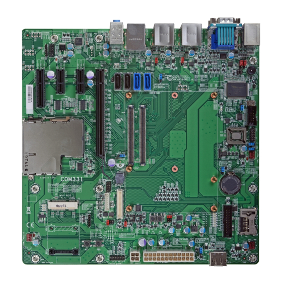
Hardware Installation Chapter 2 - Hardware Installation System Board Layout BIOS Select (JP14) (JP3) BIOS Select COM2 Thermal Trigger Buzzer (J25) SIO Fan_1 USB 3.0 (0-1) System Fan FWH Write Protect Fintek (J21) Super IO enable USB 0-1 F71879 BIOS SDIO /Disable(JP9) power select... -
Page 12: Jumper Settings
Hardware Installation Jumper Settings USB Power Select USB 0-1 (JP5) 1-2 On: 5V 2-3 On: (default) 5V_standby USB 4-7 (JP4) 1-2 On: 5V 2-3 On: USB 2-3 5V_standby (default) (JP8) JP5 (for USB 0-1), JP4 (for USB 4-7) and JP8 (for USB 2-3) are used to select the power of the USB ports. -
Page 13: Panel Power Select
Hardware Installation Panel Power Select 1-2 On: 12V 3-4 On: 5V 5-6 On: 3V (default) JP7 is used to select the power supplied to the LCD panel. Important: Before powering-on the system, make sure JP7’s setting matches the LCD panel’s specifi cation. Selecting the incorrect voltage will seriously damage the LCD panel. -
Page 14: Clear Cmos
Hardware Installation Clear CMOS JP11 1-2 On: Normal 2-3 On: (default) Clear CMOS Data If you encounter the following, a) CMOS data becomes corrupted. b) You forgot the supervisor or user password. you can reconfi gure the system with the default values stored in the ROM BIOS. To load the default values stored in the ROM BIOS, please follow the steps below. -
Page 15: Super Io Enable/ Disable
Hardware Installation Super IO Enable/ Disable 1 2 3 1-2 On: Enable 1 2 3 2-3 On: Disable (default) JP9 is used to select enable or disable the super IO select. -
Page 16: Backlight Power Select
Hardware Installation Backlight Power Select 1 2 3 1 2 3 1-2 On: +5V 2-3 On: +3.3V (default) JP6 is used to select the backlight control level +5V or +3.3V. Important: Before powering-on the system, make sure JP6’s setting matches the backlight power’s specifi... -
Page 17: Vcc5_In Power Select
Hardware Installation VCC5_IN Power Select 1-2 On: 5VSB 3-4 On: 5V 5-6 On: NC JP1 is used to select the power of the COM Express connector. -
Page 18: Pcie X16 Normal/ Reversed
Hardware Installation PCIe x16 Normal/ Reversed 1-2 On: Normal (default) JP15 2-3 On: Reversed (for cards that support reversed signals) IF you are installing a PCIe x16 card who’s signal is reversed, set JP15 pins 2 and 3 to on. -
Page 19: Bios Select
Hardware Installation BIOS Select JP14: 1-2 On JP3: 1-2 On Module SPI BIOS JP14: 2-3 On JP3: 1-2 On Carrier LPC FWH JP14: 1-2 On JP3: 2-3 On Carrier SPI0 JP14: 2-3 On JP3: 2-3 On Module SPI0 (Default) JP3 and JP14 are used to determine the BIOS boot device. -
Page 20: Fwh Write Protect
Hardware Installation FWH Write Protect 1-2 On: Enable 1-2 Off: Disable (Default) J21 is used to confi gure the BIOS Write Protect function. When this function is enabled, the system will be protected from unnecessary updating or fl ashing of the BIOS. -
Page 21: Function Test Jumper
Hardware Installation Function Test Jumpers Battery Low Test 1-2 On: Battery low test 1-2 Off: Normal (default) This jumper is used to simulate the signal status that indicates the external bat- tery is low. By setting J23 pins 1 and 2 to On, it sends a battery low signal to the module. -
Page 22: Wake-Up Test
Hardware Installation Wake-up Test 1-2 On: Wake-up test 1-2 Off: Normal (default) This jumper is used to simulate the signal status that indicates the wake-on-ring or PME# event from the Super I/O. It is also used to simulate a general purpose wake-up signal such as wake-up on PS/2 keyboard or PS/2 mouse. -
Page 23: Thermal Trigger
Hardware Installation Thermal Trigger 1-2 On: Thermal Trigger 1-2 Off: Normal (default) This jumper is used to simulate the signal status that indicates the Over Temper- ature Signal (OVT) output from the Super I/O F71879. When monitored tempera- ture exceeds the OVT value, OVT# will be asserted until the temperature goes below the hysteresis temperature. -
Page 24: Rear Panel I/O Ports
Hardware Installation Rear Panel I/O Ports PS/2 COM 1 USB 6-7 USB 4-5 KB/MS Line-in Line-out Mic-in USB 0-1 USB 2-3 The rear panel I/O ports consist of the following: • 2 Display ports • 1 COM port • VGA port •... -
Page 25: Serial (Com) Ports
Hardware Installation Serial (COM) Ports COM 2 COM 1 COM 2 The system board is equipped with 1 onboard serial port (COM 1). It is also equipped with a 9-pin connector for connecting an external serial port (COM 2). The serial ports are RS-232 asynchronous communication ports with 16C550A- compatible UARTs that can be used with modems, serial printers, remote display terminals, and other serial devices. -
Page 26: Vga Port
Hardware Installation VGA Port The VGA port is used for connecting a VGA monitor. Connect the monitor’s 15-pin D-shell cable connector to the VGA port. After you plug the monitor’s cable con- nector into the VGA port, gently tighten the cable screws to hold the connector in place. -
Page 27: Rj45 Lan Port
Hardware Installation RJ45 LAN Port The onboard RJ45 LAN port allows the system board to connect to a local area network by means of a network hub. -
Page 28: Universal Serial Bus Connectors
Hardware Installation Universal Serial Bus Connectors USB 0-1 USB 3.0 USB 4-5 USB 6-7 USB 2.0 USB 2-3 USB 3.0 USB allows data exchange between your computer and a wide range of simulta- neously accessible external Plug and Play peripherals. The system board is equipped with four onboard USB 3.0/2.0/1.1 ports (USB 0-3) and four onboard USB 2.0/1.1 ports (USB 4-7). -
Page 29: Hardware Installation
Hardware Installation Wake-On-USB Keyboard/Mouse The Wake-On-USB Keyboard/Mouse function allows you to use a USB keyboard or USB mouse to wake up a system from the S3 (STR - Suspend To RAM) state. To use this function: • Jumper Setting JP4, JP5 and/or JP8 must be set to “2-3 On: 5V_standby”. Refer to “USB Power Select”... -
Page 30: Audio
Hardware Installation Audio Line-in Line-out Rear audio Mic-in Front audio Rear Audio The system board is equipped with 3 audio jacks. A jack is a one-hole connecting interface for inserting a plug. • Line-in Jack (Light Blue) This jack is used to connect any audio devices such as Hi-fi set, CD player, tape player, AM/FM radio tuner, synthesizer, etc. -
Page 31: Internal I/O Connectors
Hardware Installation I/O Connectors S/PDIF Connector SPDIF in Ground SPDIF out The S/PDIF connector is used to connect external S/PDIF ports. Your S/PDIF ports may be mounted on a card-edge bracket. Install the card-edge bracket to an available slot at the rear of the system chassis then connect the audio cable to the S/PDIF connector. -
Page 32: Lvds Lcd Panel Connector And Lcd/Inverter Power Connector
Hardware Installation LVDS LCD Panel Connector LCD/Inverter Power Connector LVDS LCD panel LCD/Inverter power The system board allows you to connect a LCD Display Panel by means of the LVDS LCD panel connector and the LCD/Inverter power connector. These connec- tors transmit video signals and power from the system board to the LCD Display Panel. - Page 33 Hardware Installation LVDS LCD Panel Connector Pins Pins Function Function LVDS_Out3+ LVDS_Out7+ LVDS_Out3- LVDS_Out7- LVDS_Out2+ LVDS_Out6+ LVDS_Out2- LVDS_Out6- LVDS_Out1+ LVDS_Out5+ LVDS_Out1- LVDS_Out5- LVDS_Out0+ LVDS_Out4+ LVDS_Out0- LVDS_Out4- LVDS_CLK1+ LVDS_CLK2+ LVDS_CLK1- LVDS_CLK2- LVDS_DDCCLK N. C. LVDS_DDCDAA N. C. Panel Power Panel Power Panel Power Panel Power LCD/Inverter Power Connector...
-
Page 34: Digital I/O Connector
Hardware Installation Digital I/O Connector The 8-bit Digital I/O connector provides powering-on function to external devices that are connected to these connectors. Pin Assignment Pin Assignment +12V DIO7(GPO3) +12V DIO6(GPO2) DIO5(GPO1) DIO4(GPO0) DIO3(GPI3) DIO2(GPI2) 5VSB DIO1(GPI1) 5VSB DIO0(GPI0) -
Page 35: Lpc Connector
Hardware Installation LPC connector RST# FRAME# LAD3 LAD2 LAD1 VCC3 LAD0 The Low Pin Count Interface was defi ned by Intel Corporation to facilitate the in- ® dustry’s transition towards legacy free systems. It allows the integration of low- bandwidth legacy I/O components within the system, which are typically provided by a Super I/O controller. -
Page 36: Sata (Serial Ata) Connectors
Hardware Installation SATA (Serial ATA) Connectors SATA 3.0 6Gb/s SATA 0 SATA 1 SATA 2 SATA 3 SATA 2.0 3Gb/s Features • SATA 0 and SATA 1 support data transfer rate up to 6Gb/s • SATA 2 to SATA 3 support data transfer rate up to 3Gb/s •... -
Page 37: Cooling Fan Connectors
Hardware Installation Cooling Fan Connectors Power Power Ground Sense Ground Sense SIO_Fan 1 System_Fan SIO_Fan 2 Sense Ground Power The fan connectors are used to connect cooling fans. The cooling fans will pro- vide adequate airfl ow throughout the chassis to prevent overheating the module and system board components. -
Page 38: I 2 C Connector
Hardware Installation C Connector I2C_CLK I2C_DAT Ground The 1-channel I C bus interface conforms to the version 2.1 I C bus specifi cation. It operates as a master or slave device and supports a multi-master bus. -
Page 39: Sm Bus
Hardware Installation SM bus 3VDU SM Bus Data ALERT- The SMBus (System Management Bus) connector is used to connect SMBus devices. It is a multiple device bus that allows multiple chips to connect to the same bus and enable each one to act as a master by initiating data transfer. -
Page 40: Power Connectors
Hardware Installation Power Connectors +3.3VDC +5VDC +12VDC +5VDC +12VDC +5VDC +5VSB PWR_OK +5VDC PS_ON# +5VDC +3.3VDC -12VDC +3.3VDC +3.3VDC +12V Ground Ground +12V Use a power supply that complies with the ATX12V Power Supply Design Guide Version 1.1. An ATX12V power supply unit has a standard 24-pin ATX main power connector that must be inserted into the 24-pin connector. -
Page 41: Standby Power Led
Hardware Installation Standby Power LED Standby Power LED This LED will lit red when the system is in the standby mode. It indicates that there is power on the system board. Power-off the PC then unplug the power cord prior to installing any devices. Failure to do so will cause severe damage to the motherboard and components. -
Page 42: Front Panel Connectors
Hardware Installation Front Panel Connectors PWR-LED HDD-LED PWR-BTN RESET-SW HDD-LED - HDD LED This LED will light when the hard drive is being accessed. RESET SW - Reset Switch This switch allows you to reboot without having to power off the system. PWR-BTN - Power Switch This switch is used to power on or off the system. -
Page 43: Expansion Slots
Hardware Installation Expansion Slots PCI Express x16 PCI Express x1 PCI Express x1 Mini PCI Express (PCIe signal only) PCI Express x4 PCI Express x16 Slot Install PCI Express x16 graphics card, that comply to the PCI Express specifi ca- tions, into the PCI Express x16 slot. -
Page 44: Battery
Hardware Installation Battery Battery The lithium ion battery powers the real-time clock and CMOS memory. It is an auxiliary source of power when the main power is shut off. Safety Measures • Danger of explosion if battery incorrectly replaced. • Replace only with the same or equivalent type recommend by the manufac- turer. -
Page 45: Com Express Connectors
Hardware Installation COM Express Connectors COM Express Connectors (Type 6) The COM Express connectors are used to interface the carrier board with a COM Express board. Refer to the following pages for the pin functions of these connec- tors. - Page 46 Hardware Installation...
- Page 47 Hardware Installation...
- Page 48 Hardware Installation...
-
Page 49: Chassis Instrusion Connector
Hardware Installation Chassis Intrusion Connector Ground Chassis signal The board supports the chassis intrusion detection function. Connect the chas- sis intrusion sensor cable from the chassis to this connector. When the system’s power is on and a chassis intrusion occurred, an alarm will sound. When the system’s power is off and a chassis intrusion occurred, the alarm will sound only when the system restarts. -
Page 50: Display Port
Hardware Installation Display Port Display Port Display Port DisplayPort is a digital display interface used to connect a display device such as a computer monitor. It is used to transmit audio and video simultaneously. The interface, which is developed by VESA, delivers higher performance features than any other digital interface. -
Page 51: Express Card
Hardware Installation Express Card Express Card (PCIe signal only) The ExpressCard slot is an interface for high-performance, modular expansion. It uses serial data interfaces that provide improve data transfer speed. You can insert an ExpressCard such as wireless network cards, Ethernet cards, solid-state drives, or TV tuner cards. -
Page 52: Sdio
Hardware Installation SDIO SDIO This expansion port is used to insert a Secure Digital Input/Output (SDIO) or Multimedia Card (MMC) device. Aside from storing data fi les, an SDIO card is also capable of storing powerful software applications. -
Page 53: Switches
Hardware Installation Switches Sleep Power Reset Note: The Sleep and Lid functions are supported only when your operating system supports ACPI. • Sleep: it is used to set the system to “sleep” or “wake-up” mode. • Lid: it is used to turn the LVDS on or off. -
Page 54: Serial Interface Connector
Hardware Installation Serial Interface Connector Serial Interface 0 (Rx/Tx) Serial Interface 1 (Rx/Tx) This serial interface connectors are used to any device supported Tx and Rx sig- nal. -
Page 55: Chapter 3 - Supported Software
Supported Software Chapter 3 - Supported Software The CD that came with the system board contains drivers, utilities and software applications required to enhance the performance of the system board. Insert the CD into a CD-ROM drive. The autorun screen (Mainboard Utility CD) will appear. -
Page 56: Audio Drivers
Supported Software Audio Drivers To install the driver, click “Audio Drivers” on the main menu. 1. Setup is now ready to in- stall the audio driver. Click Next. 2. Follow the remainder of the steps on the screen; click- ing “Next” each time you fi... -
Page 57: Adobe Acrobat Reader
Supported Software Adobe Acrobat Reader 9.3 To install the reader, click “Adobe Acrobat Reader 9.3” on the main menu. 1. Click Next to install or click Change Destination Folder to select another folder. 2. Click Install to begin instal- lation. 3.
Need help?
Do you have a question about the COM331-B and is the answer not in the manual?
Questions and answers