DFI CS551-C246 User Manual
Embedded sbc 3.5” industrial motherboard
Hide thumbs
Also See for CS551-C246:
- Quick reference (4 pages) ,
- Quick reference (4 pages) ,
- Quick reference (4 pages)

Related Manuals for DFI CS551-C246


Summary of Contents for DFI CS551-C246
- Page 1 CS551-C246/Q370/H310 Embedded SBC 3.5” Industrial Motherboard User’s Manual Preliminary Preliminary Version Version A-590-M-2014...
- Page 2 Copyright FCC and DOC Statement on Class B This publication contains information that is protected by copyright. No part of it may be repro- This equipment has been tested and found to comply with the limits for a Class B digital duced in any form or by any means or used to make any transformation/adaptation without the device, pursuant to Part 15 of the FCC rules.
-
Page 3: Table Of Contents
Table of Contents Chapter 1 - Introduction........................ 6 Specifications ......................... 6 Features ..........................7 DDR4 ..........................7 Chapter 2 - Hardware Installation ....................8 Board Layout........................... 8 Standby Power LED ........................ 8 System Memory ........................9 Installing the SO-DIMM Module ..................9 CPU ............................11 Installing the CPU ......................11 Installing the Heatsink and Fan ..................13... - Page 4 About this Manual Static Electricity Precautions This manual can be downloaded from the website, or acquired as an electronic file included in It is quite easy to inadvertently damage your PC, system board, components or devices even the optional CD/DVD. The manual is subject to change and update without notice, and may be before installing them in your system unit.
- Page 5 About the Package The package contains the following items. If any of these items are missing or damaged, please contact your dealer or sales representative for assistance. • One CS551 board • One COM port cable (Length: 250mm, 1 DB9 port) •...
-
Page 6: Chapter 1 - Introduction
REAR I/O Ethernet 2 x GbE (RJ-45) resemble your actual products. Please visit the download page at go.dfi. com/CS551, or via the QR code to the right for the latest datasheet. 4 x USB 3.1 Gen2 (C246/Q370) or Gen1 (H310) Display... -
Page 7: Features
Chapter 1 INTRODUCTION X Features Watchdog Timer ACPI STR The Watchdog Timer function allows your application to regularly “clear” the system at the set The system board is designed to meet the ACPI (Advanced Configuration and Power Interface) time interval. If the system hangs or fails to function, it will reset at the set time interval so that specification. -
Page 8: Chapter 2 - Hardware Installation
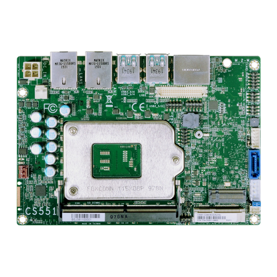
Chapter 2 HARDWARE INSTALLATION Chapter 2 - Hardware Installation X Board Layout Note: Specifications of these components are model-specific. Please refer to the specifi- cations for detail. USB 3/4 (left), 1/2 (right) LED1 (USB 3.1 Note LAN1 LAN2 DP++1/2 Important: Electrostatic discharge (ESD) can damage your board, processor, disk drives, Front Audio... -
Page 9: System Memory
Chapter 2 HARDWARE INSTALLATION X System Memory System Memory Installing the SO-DIMM Module Before installing the memory module, please make sure that the following safety cautions are well-attended. 1. Make sure the PC and all other peripheral devices connected to it has been powered down. - Page 10 Retention Clip Chapter 2 HARDWARE INSTALLATION Socket Top View System Memory Installing the SO-DIMM Module Please follow the steps below to install the memory card into the socket. Step 1: Insert the memory card into the slot while making sure 1) the notch and the key are aligned, and 2) the non-connector end 4 5 °...
-
Page 11: Cpu
Chapter 2 HARDWARE INSTALLATION X CPU Installing the CPU 1. Make sure the PC and all other peripheral devices connected to it have been powered down. The system board is equipped with a surface mount LGA 1151 socket. This socket is exclu- sively designed for installing a LGA 1151 packaged Intel CPU. - Page 12 Chapter 2 HARDWARE INSTALLATION Installing the CPU Installing the CPU Load lever 7-2. Two keys on the sock- 5. Lift the load lever and the load plate all the way up as shown in et and notches on the Alignment key CPU also facilitate the photo.
-
Page 13: Installing The Heatsink And Fan
Chapter 2 HARDWARE INSTALLATION Please make sure the contacting sides of the Installing the Heatsink and Fan heat spreader and the module are correct — the CPU side of the module shall be facing the interface metal side and legs of the heat sink. The system board may come with a heatsink or a cooler (heatsink with fan), including four Rotate horozontally so the interface metal sits stand-offs and four stand-off screws to secure the board and heatsink onto the chassis. - Page 14 Chapter 2 HARDWARE INSTALLATION Installing the Heatsink and Fan Place the heatsink and module combo onto the stand-offs. Make sure the stand-off screw holes on the combo and those on the stand- offs align. Place the stand-off screws provided in the package into the screw holes of the combo.
-
Page 15: Jumper Settings
SPI Flash BIOS Buzzer Chapter 2 LVDS HARDWARE INSTALLATION Backlight Power USB 3/4 (left), 1/2 (right) X Jumper Settings Clear CMOS (JP2) (USB 3.1 Note SATA 3.0 Front Panel (JP5) CPU Fan DP++1/2 M Key Front SATA Audio Power LVDS Battery USB 5/6 (USB 2.0) COM1... -
Page 16: Panel Power Select (Jp3)
USB 3/4 (left), 1/2 (right) LED1 (USB 3.1 Note Chapter 2 HARDWARE INSTALLATION LAN1 LAN2 DP++1/2 Jumper Settings Jumper Settings Front Panel Power Select (JP3) Backlight Power Select (JP1) USB 3/4 (left), 1/2 (right) Audio (USB 3.1 Note LVDS Heater and Switch USB 5/6 (USB 2.0) COM1 DP++1/2... -
Page 17: Rear I/O Ports
Chapter 2 HARDWARE INSTALLATION X Rear I/O Ports Rear I/O Ports Graphics Display „ DP++ 1 „ DP++ 2 „ 2 x DP++ „ 4 x USB 3.1 „ LAN 2 „ LAN 1 The rear panel I/O ports consist of the following: •... -
Page 18: Usb Ports
Chapter 2 HARDWARE INSTALLATION Rear I/O Ports Rear I/O Ports USB Ports RJ45 LAN Ports „ LAN 2 „ LAN 1 „ USB 2 (USB 3.1) „ USB 4 (USB 3.1) „ USB 1 (USB 3.1) „ USB 3 (USB 3.1) The two LAN ports allow the system board to connect to a local area network by means of a network hub. -
Page 19: Internal I/O Connectors
Chapter 2 HARDWARE INSTALLATION USB 3/4 (left), 1/2 (right) LED1 X Internal I/O Connectors Internal I/O Connectors (USB 3.1 Note COM (Serial) Port 12V DC-In LAN1 LAN2 DP++1/2 Front USB 3/4 (left), 1/2 (right) LED1 Audio (USB 3.1 Note LVDS Heater and Switch USB 5/6 (USB 2.0) COM1... -
Page 20: Front Audio
Chapter 2 HARDWARE INSTALLATION USB 3/4 (left), 1/2 (right) Internal I/O Connectors Internal I/O Connectors LED1 (USB 3.1 Note Front Audio USB Ports DP++1/2 LAN1 LAN2 USB 3/4 (left), 1/2 (right) (USB 3.1 Note LVDS LAN2 DP++1/2 Heater and Switch USB 5/6 (USB 2.0) Front Audio... -
Page 21: Chassis Intrusion
LVDS Chapter 2 Heater and Switch HARDWARE INSTALLATION USB 5/6 (USB 2.0) COM1 Internal I/O Connectors Internal I/O Connectors SPI Flash BIOS Intel SATA (Serial ATA) Buzzer Socket LGA1151 LVDS The LPC connector is used for debugging. Backlight Power C246/Q370/H310 SATA 3.0 CPU Fan M Key... -
Page 22: Battery
DP++1/2 LAN1 LAN2 Chapter 2 HARDWARE INSTALLATION LVDS Internal I/O Connectors Internal I/O Connectors Heater and Switch USB 5/6 (USB 2.0) Battery CPU Fan SPI Flash BIOS „ Battery CPU Fan DDR4_1 SODIMM Connect to board These fan connectors are used to connect to cooling fans. Cooling fans provide adequate air SMBus circulation throughout the chassis and dissipate heat to prevent overheating of the system board and components. -
Page 23: Digital I/O
Buzzer USB 3/4 (left), 1/2 (right) LED1 Chapter 2 (USB 3.1 Note HARDWARE INSTALLATION Internal I/O Connectors Internal I/O Connectors LAN1 LAN2 DP++1/2 Digital I/O SMBus Front CPU Fan Audio LVDS M Key Heater and Switch USB 5/6 (USB 2.0) COM1 SPI Flash BIOS Buzzer... -
Page 24: Lvds Panel
Chapter 2 HARDWARE INSTALLATION Internal I/O Connectors LVDS Panel „ LVDS LCD Panel Pin Function Pin Function USB 3/4 (left), 1/2 (right) Pin Assignment LED1 (USB 3.1 Note LVDSA_Out3+ LVDSB_Out3+ LVDSA_Out3- LVDSB_Out3- LAN1 LAN2 DP++1/2 USB 3/4 (left), 1/2 (right) Front (USB 3.1 Note... -
Page 25: Heater
Chapter 2 HARDWARE INSTALLATION Internal I/O Connectors Internal I/O Connectors Heater Expansion Slots USB 3/4 (left), 1/2 (right) LED1 (USB 3.1 Note DP++1/2 LAN1 LAN2 Front Audio LVDS Heater and Switch USB 5/6 (USB 2.0) COM1 M.2 M Key Mini PCIe SPI Flash BIOS Buzzer LVDS... -
Page 26: Expansion Slots
Chapter 2 HARDWARE INSTALLATION Internal I/O Connectors Expansion Slots Installing the M.2 Module Before installing the M.2 module into the M.2 socket, please make sure that the following Please follow the steps below to install the card into the socket. safety cautions are well-attended. -
Page 27: Installing The Mini Pcie Module
Chapter 2 HARDWARE INSTALLATION Internal I/O Connectors Expansion Slots Installing the Mini PCIe Module Please follow the steps below to install the card into the socket. Before installing the Mini PCIe module into the Mini PCIe socket, please make sure that the fol- lowing safety cautions are well-attended.
Need help?
Do you have a question about the CS551-C246 and is the answer not in the manual?
Questions and answers