
Related Manuals for JETWAY PT88AS - REV 1.0


Summary of Contents for JETWAY PT88AS - REV 1.0
- Page 1 PT88AS/PT8AS User's Manual Intel Socket 478 Processor Motherboard VIA PT880/PT800 + VIA 8237 NO. G03-PT88AS Revision 1.0...
-
Page 2: Table Of Contents
Table of Content Manual Revision History........................ii Copyright Announcement ......................... ii Trademarks Notice ..........................ii Safety Instructions ..........................iii Packing Item Checklist.......................... iv Intel Pentium 4 Socket 478 Processor Thermal Solutions..............iv CHAPTER 1 INTRODUCTION OF MOTHERBOARD FEATURE OF MOTHERBOARD ..................1 SPECIFICATION........................ -
Page 3: Manual Revision History
Manual Revision History Revision Manual Revision History Date of Release Rev 1.0 First Edition copy of Mother Boards 2004/07/26 adopts VIA Chipsets: VIA PT880/PT800 and VIA VT8237 Copyright Announcement COPYRIGHT OF THIS MANUAL BELONGS TO THE MANUFACTURER. NO PART OF THIS MANUAL, INCLUDING THE PRODUCTS AND SOFTWARE DESCRIBED IN IT MAY BE REPRODUCED, TRANSMITTED OR TRANSLATED INTO ANY LANGUAGE IN ANY FORM OR BY ANY MEANS WITHOUT WRITTEN PERMISSION OF THE MANUFACTURER. -
Page 4: Safety Instructions
PS/2 and OS®/2 are registered trademarks of International Business Machines Corporation. PCMCIA and CardBus are registered trademarks of the Personal Computer Memory Card International Association. Windows® 98/2000/NT/XP are registered trademarks of Microsoft Corporation. **The ranking above is by the sequence of alphabets.** Safety Instructions Please read these safety instructions carefully. -
Page 5: Packing Item Checklist
Packing Item Checklist Motherboard Cable for IDE/Floppy Cable for Serial ATA IDE Port CD for motherboard utilities Cable for USB Port 3/4 (Option) User’s Manual Intel Pentium 4 Socket478 Processor Thermal Solutions As processor technology pushes to faster speeds and higher performance, thermal management becomes increasingly crucial when building computer systems. -
Page 6: Feature Of Motherboard
Chapter 1 Introduction of PT88AS/PT8AS Motherboard Thank you for purchasing the PT88AS which provide extremely performance and meet future specification demand. PT88AS/PT8AS series motherboards are adopted with advanced technologies to deliver the extremely performance for Intel Pentium 4 Northwood/ Hyper-Threading/ Prescott socket 478 processors. -
Page 7: Specification
1-2 Specification Spec Description ∗ ATX form factor 4 layers PCB size: 30.5x18.0cm Design ∗ VIA PT880 North Bridge Chipset for PT88AS Chipset ∗ VIA PT800 North Bridge Chipset for PT8AS ∗ VIA VT8237 South Bridge ∗ Support Intel Pentium 4 478-Pin package utilizes Flip-Chip Pin CPU Socket Grid Array (FC-PGA2) package processor ∗... -
Page 8: Performance List
1-3 Performance List The following performance data list is the testing result of some popular benchmark testing programs. These data are just referred by users, and there is no responsibility for different testing data values gotten by users (the different Hardware & Software configuration will result in different benchmark testing results.) Performance Test Report CPU:... -
Page 9: Layout Diagram & Jumper Setting
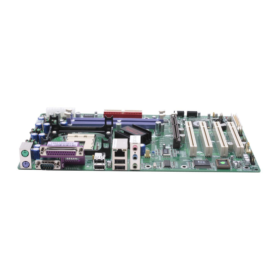
1-4 Layout Diagram & Jumper Setting PRINT PS/2 Mouse LINE-IN PS/2 Keyboard LINE-OUT COM1 USB1 ATX 12V Power Connector K/B Power ON Jumper (JP1) PS2 KB/Mouse Port CPU FAN ATX Power Connector PC99 Back Panel CPU Socket USB Power On Jumper (JP2) DDR DIMM X2 USB Port USB Port/LAN Connector... - Page 10 Jumpers Jumper Name Description Page JBAT CMOS RAM Clear 3-pin Block JP2, JP3 USB Power On Enable/Disabled 3-pin Block Keyboard Power On Enable/ Disabled 3-pin Block Connectors Connector Name Description Page ATXPWR ATX Power Connector 20-pin Block P.13 ATX12V ATX 12V Power Connector 4-pin Block P.13 PS2KBMS...
-
Page 11: Chapter 2 Hardware Installation
Chapter 2 Hardware installation 2-1 Pre-Hardware installation Before starting to use the computer with the motherboard installed the components on it, please make sure complete the following steps: To verify the jumper settings of your motherboard To install the CPU and Cooling Kits To install the system memory To install the expansion cards To connect with ribbon cables, panel wires, and power supply... - Page 12 (2) Keyboard/USB Power On function Enabled/Disabled: JP1/JP2, JP3 When setting Enabled you can using keyboard by key in password/USB to power on system. 1-2 closed K/B Power ON Disable 2-3 closed K/B Power ON Enabled (Default) Keyboard Power On Setting 1-2 closed USB Power On Disable 2-3 closed...
-
Page 13: To Install The Cpu
2-3 To install the CPU 3-1 Glossary Chipset (or core logic) - two or more integrated circuits which control the interfaces between the system processor, RAM, I/O devises, and adapter cards. Processor socket - the socket used to mount the system processor on the motherboard. Slot (AGP, PCI, ISA, RAM DIMMs) - the slots used to mount adapter cards and system RAM. -
Page 14: About Intel Pentium 4 478-Pin Cpu
2-3-2 About INTEL PENTIUM 4 478-PIN CPU This motherboard provides a 478-pin surface mount, Zero Insertion Force (ZIF) socket, referred to as the mPGA478B socket supports Intel Pentium 4 processor in the 478 Pin package utilizes Flip-Chip Pin Grid Array (FC-PGA2) package technology. The CPU that comes with the motherboard should have a cooling FAN attached to prevent overheating. -
Page 15: To Install The System Memory
2-4 To install the system memory This motherboard provides 184-pin DUAL INLINE MEMORY MODULES (DIMM) sites for memory expansion available from minimum memory size of 64MB to maximum memory size of 2.0GB DDR SDRAM. Valid Memory Configurations Bank 184-Pin DIMM Total Memory Bank 0, 1 (DIMM1) DDRDDR266/DDR333/DDR400 64MB∼1.0GB... -
Page 16: To Install The Expansion Cards
2-5 To install the Expansion Cards WARNING! Turn off your power when adding or removing expansion cards or other system components. Failure to do so may cause severe damage to both your motherboard and expansion cards. 2-5-1 Procedure For Expansion Card Installation To read documentations or manuals for your expansion cards and make any necessary hardware or software settings for your expansion card such as jumpers. -
Page 17: Interrupt Request Table For This Motherboard
2-5-3 Interrupt Request Table For This Motherboard IMPORTANT! While using PCI cards on shared slots, make sure that the drivers support “Shared IRQ” or that the cards don’t need IRQ assignments. Conflicts will arise between the two PCI groups that will make the system unstable or cards inoperable. -
Page 18: Connectors And Pin Headers
2-6 Connectors and pin headers 2-6-1 Connectors (1) Power Connector (20-pin block) : ATXPWR ATX Power Supply connector. This is a new defined 20-pins connector that usually comes with ATX case. The ATX Power Supply allows to use soft power on momentary switch that connect from the front panel switch to 2-pins Power On jumper pole on the motherboard. - Page 19 (5) LAN Port connector: LAN This connector is standard RJ45 connector for Network (6) Parallel Port connector (25-pin D-sub connector): PARALLEL (7) Serial Port connector: COM1 The connectors is 9-pin Male connector that connect serial devices to the system board. (8) Audio Connector: CN1 This Connector are 3 phone Jack for LINE-OUT, LINE-IN, MIC.
- Page 20 IDE1 IDE2 Pin 1 Pin 1 Primary IDE Connector (11) Secondary IDE Connector (40-pin block): IDE2 This connector connects to the next set of Master and Slave hard disks. Follow the same procedure described for the primary IDE connector. You may also configure two hard disks to be both Masters using one ribbon cable on the primary IDE connector and another ribbon cable on the secondary IDE connector.
-
Page 21: Pin Headers
2-6-2 Pin headers (1) Line-Out, MIC Header (9-pin): AUDIO This header connect to Front Panel Line-out, MIC connector with cable. AUDIO Pin 1 Line-Out, MIC Headers (2) USB Port Headers (9-pin) : USB2, USB3 These headers are used for connecting the additional USB port plug. By attaching an option USB cable, your can be provided with two additional USB plugs affixed to the back panel. - Page 22 (7) Power LED: PWR LED The Power LED is light on while the system power is on. Connect the Power LED from the system case to this pin. PWRLED JW FP Pin 1 Pin 1 SPEAK Pin 1 System Case Connections (8) FAN Headers (3-pin) : SFAN1, SFAN2, CPUFAN These connectors support cooling fans of 350mA (4.2 Watts) or less, depending on the fan manufacturer, the wire and plug may be different.
-
Page 23: Starting Up Your Computer
2-7 Starting up your computer 1. After all connection are ready, close your computer case cover. 2. Be sure all the switches are off, and check that the power supply input voltage is set to proper position, usually in-put voltage is 220V∼240V or 110V∼120V depending on your country’s voltage used. -
Page 24: Chapter 3 Introducing Bios Settings
Chapter 3 Introducing BIOS Settings The BIOS is a program located on a Flash Memory of the motherboard. Using this program as a bridge between motherboard and operating system. When the computer starting to work, the BIOS program gain control. The BIOS first operates an auto-diagnostic test called POST (power on self test) for all the necessary hardware, it detects the entire hardware device and configures the parameters of the hardware synchronization. -
Page 25: Getting Help
3-2 Getting Help Main Menu The on-line description of the highlighted setup function is displayed at the bottom of the screen. Status Page Setup Menu/Option Page Setup Menu Press F1 to pop up a small help window that describes the appropriate keys to use and the possible selections for the highlighted item. - Page 26 Standard CMOS Features Use this Menu for basic system configurations. Advanced BIOS Features Use this menu to set the Advanced Features available on your system. Advanced Chipset Features Use this menu to change the values in the chipset registers and optimize your system’s performance.
-
Page 27: Standard Cmos Features
3-4 Standard CMOS Features The items in Standard CMOS Setup Menu are divided into several categories. Each category includes no, one or more than one setup items. Use the arrow keys to highlight the item and then use the <PgUp> or <PgDn> keys to select the value you want in each item. CMOS Setup Utility –... -
Page 28: Advanced Bios Features
3-5 Advanced BIOS Features CMOS Setup Utility – Copyright(C) 1984-2004 Award Software Advanced BIOS Features Virus Warning Disabled Item Help CPU L1 & L2 Cache Enabled CPU L3 Cache Enabled CPU L2 Cache ECC Checking Disabled Quick Power On Self Test Enabled Menu Level >... - Page 29 Quick Power On Self-Test This category speeds up Power On Self Test (POST) after you power on the computer. If this is set to Enabled. BIOS will shorten or skip some check items during POST. Enabled (default) Enable quick POST Disabled Normal POST First/Second/Third/Fourth Boot Device...
-
Page 30: Advanced Chipset Features
3-6 Advanced Chipset Features The Advanced Chipset Features Setup option is used to change the values of the chipset registers. These registers control most of the system options in the computer. CMOS Setup Utility – Copyright(C) 1984-2004 Award Software Advanced Chipset Features >... -
Page 31: Dram Timing Settings
3-6-1 DRAM Timing Settings CMOS Setup Utility – Copyright(C) 1984-2004 Award Software DRAM Timing Settings System Performance Auto By SPD Item Help RAS Active Time RAS Precharge Time Menu Level >> RAS to CAS Delay DRAM CAS Latency Bank Interleave Disabled DRAM Bus Select Auto... -
Page 32: Pci Timing Settings
3-6-3 PCI Timing Settings CMOS Setup Utility – Copyright(C) 1984-2004 Award Software PCI Timing Settings PCI Master 1 WS Write Disabled Item Help PCI Master 1 WS Read Disabled Menu Level >> CPU to CPI Post Write Enabled PCI Delay Transaction Enabled Vlink Mode Selection Mode 1... -
Page 33: Onchip Ide Function
3-7-1 OnChip IDE Function CMOS Setup Utility – Copyright(C) 1984-2004 Award Software OnChip IDE Function OnChip IDE Channel0 Enabled Item Help OnChip IDE Channel1 Enabled Primary Master Auto Menu Level >> Primary Slave Auto Secondary Master PIO Auto Secondary Slave PIO Auto Primary Master UDMA... -
Page 34: Onchip Device Function
3-7-2 OnChip Device Function CMOS Setup Utility – Copyright(C) 1984-2004 Award Software OnChip Device Function VIA SATA Function Enabled Item Help VIA LAN Function Enabled VIA LAN BootROM Disabled Menu Level >> VIA LAN BootROM Option Hook IN T19 Current VIA MAC Address is 003018-XXXXXX VIA MAC Address Input Press Enter... - Page 35 Onboard FDD Controller Select Enabled if your system has a floppy disk controller (FDD) installed on the system board and you wish to use it. If you install add-on FDC or the system has no floppy drive, select Disabled in this field.
-
Page 36: Power Management Setup
3-8 Power Management Setup The Power Management Setup allows you to configure your system to most effectively save energy saving while operating in a manner consistent with your own style of computer use. CMOS Setup Utility – Copyright(C) 1984-2004 Award Software Power Management Setup ACPI Function Enabled... -
Page 37: Wake Up Events
3-8-1 Wake up Events CMOS Setup Utility – Copyright(C) 1984-2004 Award Software Wake Up Events Item Help LPT & COM LPT/COM HDD & FDD Menu Level >> PCI Master Wake-Up on Ring/LAN Disabled Wake-Up on PCI PME Disabled PS2 KB Wakeup Selection Hot Key Wake-Up on Hot Key (PS KB) Disabled... -
Page 38: Pnp/Pci Configuration Setup
3-9 PnP/ PCI Configuration Setup This section describes configuring the PCI bus system. PCI, or Personal Computer Interconnect, is a system which allows I/O devices to operate at speeds nearing the speed the CPU itself uses when communicating with its own special components. This section covers some very technical items and it is strongly recommended that only experienced users should make any changes to the default settings. -
Page 39: Irq Resources
3-9-1 IRQ Resources CMOS Setup Utility – Copyright(C) 1984-2004 Award Software IRQ Resources IRQ3 assigned to PCI Device Item Help IRQ4 assigned to PCI Device Menu Level >> IRQ5 assigned to PCI Device IRQ7 assigned to PCI Device IRQ9 assigned to PCI Device IRQ10 assigned to PCI Device... -
Page 40: Miscellaneous Control
3-11 Miscellaneous Control This section is for setting CPU Frequency/Voltage Control. CMOS Setup Utility – Copyright(C) 1984-2004 Award Software Miscellaneous Control CPU Clock Ratio Item Help Auto Detect DIMM/PCI Clock Enabled Menu Level > Spread Spectrum Disabled ** Current Host Clock is 100/33MHz ** Host/PCI Clock at Next Boot 100/33MHz ** Current DRAM Clock is 133MHz **... -
Page 41: Load Standard/Optimized Defaults
3-12 Load Standard/Optimized Defaults Load Standard Defaults When you press <Enter> on this item, you get confirmation dialog box with a message similar Load Standard Defaults (Y/N)? N Pressing <Y> loads the BIOS default values for the most stable, minimal-performance system operations. -
Page 42: Chapter 4 Driver & Free Program Installation
Chapter 4 DRIVER & FREE PROGRAM INSTALLATION Check your package and there is A MAGIC INSTALL CD included. This CD consists of all DRIVERS you need and some free application programs and utility programs. In addition, this CD also include an auto detect software which can tell you which hardware is installed, and which DRIVERS needed so that your system can function properly. -
Page 43: Via 4In1 Install Via Service Pack 4 In 1 Driver
4-1 VIA 4IN1 Install VIA Service Pack 4 IN 1 Driver The path of the file is X:\VIA\DRIVER\SETUP.EXE IDE : VIA ATAPI VENDOR SUPPORT DRIVER IS USED TO FIXED COMPATIBILITY ISSUE FOR IDE DEVICES AGPVXD : VIA AGPVXD DRIVER IS TO BE INSTALLED, IF YOU ARE USING AN AGP VGA CARD, VIAGART.VXD WILL PROVIDE SERVICE ROUTINES TO YOUR VGA DRIVER AND INTERFACE DIRECTLY TO HARDWARE, PROVIDING FAST GRAPHIC ACCESS... -
Page 44: Sound Install Via Ac97 Codec Audio Driver
7. Click NEXT to Install VIA AGP VXD Driver 8. Click NEXT to Install VIA IRQ Routing Mini port Driver 9. Click Finish to restart computer 4-2 SOUND install VIA AC97’ Codec Audio Driver 1. Click SOUND when MAGIC INSTALL 2. - Page 45 Sound Effect select and KaraOK Mode Manual Sound Effect Setting Function 2/4/6 channel speaker configuration setting 8. 6 channel speaker place test Note: The path of the file For WIN98/NT4.0/WIN2K/XP is X:\CODEC\ALC\SETUP.EXE Note: In Win2K/WinME users have to click Control Panel\System\Device Manager\ DVD\CD-ROM drives to Enabled digital CD Audio for the CD-ROM Device when use the SPDIF-Out digital signal.
-
Page 46: Lan Install Via Lan Controller Driver
4-3 LAN Install VIA LAN Controller Driver The VIA 10/100Mb PCI Ethernet Adapter Driver path is X:\VIA\LANDRV Click LAN when Magic Install Menu appear 2. Setup VIA 10/100Mb PCI Ethernet Driver Driver install Finish, Click Yes and Restart When windows ask VIA 10/100Mb PCI Computer Ethernet Adapter driver path, Change directory to X:\VIA\LANDRV and click OK,... -
Page 47: Magic Bios Install Bios Live Update Utility
executing Program → ITE Smart Guardian , Click Finish , complete install ITE Smart Guardian utility The ITE Smart Guardian auto detect system voltage, Fan speed and CPU/ SYSTEM Temperature. Because this is a On-time Monitoring program therefore the value will change after it detected , if the value is over default setting the system will have warning picture and beeps... - Page 48 When On-line update BIOS the program will Click Next if you need update BIOS, after auto-check your BIOS version upgrade BIOS, the system will clear CMOS and automatically restart When System programming BIOS don’t turn Click Yes if you want to update the BIOS off power, after finish update BIOS, the otherwise choose No to exit system will clear CMOS and automatically...
-
Page 49: Pc-Cillin Install Pc-Cillin2004 Anti-Virus Program
PC-CILLIN Install PC-CILLIN 2004 Anti-virus program Click PC-CILLIN when MAGIC INSTALL Click NEXT when the "Trend Micro internet MENU appear security" installshield wizard windows appear This is license agreement, select "I Accept the Click NEXT and Enter your Customer terms" and Click NEXT Information, Click NEXT or choose Change to change the path for the file to be stored Click INSTALL, Start to install the software... -
Page 50: Usb2.0 Install Via Usb2.0 Device Driver
After PC-CILLIN 2004 complete, Please register your information and we recommend select update item to download newest engine code and virus code Note : Please install ACROBAT READER, Before you read PC-CILLIN 2004 User Manual, the path at X:\acrobat\adberdr6_enu_full.exe USB2.0 Install VIA USB2.0 DEVICE DRIVER Click USB2.0 when MAGIC INSTALL When USB2.0 Setup Program Appear, Click MENU Appear... -
Page 51: Sata Install Via Serial Ata Driver
Check device working properly in Device Manager The Path of the file is X:\VIA\VIAUSB20\SETUP.EXE SATA Install VIA Serial ATA Click SATA when MAGIC INSTALL MENU Start install VIA serial ATA driver , then click appears NEXT When license agreement appear, choose I Select you want to install driver agree and click NEXT Review install driver and utility component,... -
Page 52: How To Disable On-Board Sound
Making SATA HDD driver diskette before Install WindowsXP/2000 If you only have Serial ATA HDDs on your system, before you install the Windows XP or Windows 2000, you will need to make a SATA HDD driver diskette before you start to install the Operating System.
Need help?
Do you have a question about the PT88AS - REV 1.0 and is the answer not in the manual?
Questions and answers