Table of Contents
Advertisement
PM9MS/PM9M
PT9MS/PT9M
USER'S MANUAL
M/B For Socket 478 Pentium 4 Processor
NO. G03-PM9MS
Rev:2.0
Release date: November 2004
Trademark:
* Specifications and Information contained in this documentation are furnished for information use only, and are
subject to change at any time without notice, and should not be construed as a commitment by manufacturer.
Advertisement
Table of Contents

Related Manuals for JETWAY PM9M - REV 2.0


Summary of Contents for JETWAY PM9M - REV 2.0
- Page 1 PM9MS/PM9M PT9MS/PT9M USER'S MANUAL M/B For Socket 478 Pentium 4 Processor NO. G03-PM9MS Rev:2.0 Release date: November 2004 Trademark: * Specifications and Information contained in this documentation are furnished for information use only, and are subject to change at any time without notice, and should not be construed as a commitment by manufacturer.
-
Page 2: Table Of Contents
TABLE OF CONTENT USER’S NOTICE........................ii MANUAL REVISION INFORMATION ................ii COOLING SOLUTIONS ......................ii CHAPTER 1 INTRODUCTION OF PM9MS/PM9M/ PT9MS/PT9M FEATURE OF MOTHERBOARD ..................1 SPECIFICATION........................2 PERFORMANCE LIST ......................3 LAYOUT DIAGRAM & JUMPER SETTING ..............4 CHAPTER 2 HARDWARE INSTALLATION HARDWARE INSTALLATION STEPS ................ -
Page 3: User's Notice
USER’S NOTICE COPYRIGHT OF THIS MANUAL BELONGS TO THE MANUFACTURER. NO PART OF THIS MANUAL, INCLUDING THE PRODUCTS AND SOFTWARE DESCRIBED IN IT MAY BE REPRODUCED, TRANSMITTED OR TRANSLATED INTO ANY LANGUAGE IN ANY FORM OR BY ANY MEANS WITHOUT WRITTEN PERMISSION OF THE MANUFACTURER. THIS MANUAL CONTAINS ALL INFORMATION REQUIRED TO USE PM9MS/PM9M/ PT9MS/PT9M MOTHER-BOARD AND WE DO ASSURE THIS MANUAL MEETS USER’S REQUIREMENT BUT WILL CHANGE, CORRECT ANY TIME WITHOUT NOTICE. -
Page 4: Feature Of Motherboard
Chapter 1 Introduction of PM9MS/PM9M/PT9MS/PT9M Motherboard 1-1 Feature of motherboard The PM9MS/PM9M/PT9MS/PT9M motherboard is design for use Intel Pentium 4 Processor in 478 Pin Package Processor with the VIA PM800/PT800 Chipset delivers a high performance and professional desktop platform solution. Which utilize the Socket 478 design and the memory size expandable to 2.0GB. -
Page 5: Specification
1-2 Specification Spec Description ∗ Micro ATX form factor 4 layers PCB size: 24.4x20.0cm Design ∗ VIA PM800 North Bridge Chipset for PM9MS/PM9M Chipset ∗ VIA PT800 North Bridge Chipset for PT9MS/PT9M ∗ VIA VT8237 South Bridge Chipset ∗ Support Intel Pentium 4 478 Pin package utilizes Flip-Chip Pin CPU Socket (mPGA478B Socket) Grid Array (FC-PGA2) package processor... -
Page 6: Performance List
1-3 Performance List The following performance data list is the testing result of some popular benchmark testing programs. These data are just referred by users, and there is no responsibility for different testing data values gotten by users (the different Hardware & Software configuration will result in different benchmark testing results.) Performance Test Report Intel Pentium4 3GHz (FSB 800) Hyper-Threading Support... -
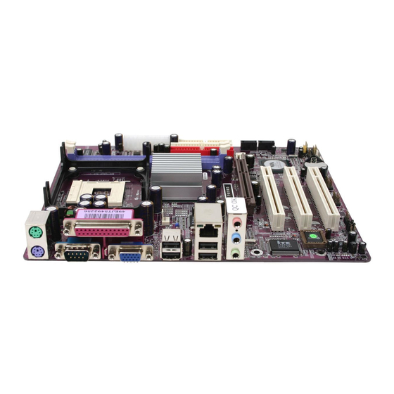
Page 7: Layout Diagram & Jumper Setting
1-4 Layout Diagram & Jumper Setting (for PM9MS/PT9MS) PRINT PS/2 Mouse LINE-IN PS/2 Keyboard LINE-OUT COM1 USB1 (for PM9MS/PM9M) K/B Power ON Jumper (JP1) CPU Socket PS2 KB/Mouse Port PC99 Back Panel DDR Socket X2 ATX Power Connector CPU FAN VIA PM800/PT800 USB Port USB Power On Jumper (JP3) - Page 8 Jumpers Jumper Name Description Page CMOS RAM Clear JBAT 3-pin Block Keyboard Power On Enable/Disabled 3-pin Block USB Power On Enable/Disabled JP3/JP4 3-pin Block Connectors Connector Name Description Page ATXPWR ATX Power Connector 20-pin Block P.11 ATX12V ATX 12V Power Connector 4-pin Block P.12 PS2KBMS...
-
Page 9: Chapter 2 Hardware Installation
Chapter 2 Hardware installation 2-1 Hardware installation Steps Before using your computer, you had better complete the following steps: 1. Check motherboard jumper setting 2. Install CPU and Fan 3. Install System Memory (DIMM) 4. Install Expansion cards 5. Connect IDE and Floppy cables, Front Panel /Back Panel cable 6. -
Page 10: Install Cpu
(2) Keyboard/USB Power On function Enabled/Disabled: JP1, JP3/JP4 1-2 closed K/B Power ON Disable 2-3 closed K/B Power ON Enabled (Default) Keyboard Power On Setting 1-2 closed USB Power On Disable 2-3 closed USB Power On Enabled (Default) USB Power On Setting 2-3 Install CPU 2-3-1 Glossary Chipset (or core logic) - two or more integrated circuits which control the interfaces between... -
Page 11: About Intel Pentium 4 478-Pin Cpu
BIOS (Basic Input/Output System) - the program logic used to boot up a computer and establish the relationship between the various components. Driver - software, which defines the characteristics of a device for use by another device or other software. Processor - the "central processing unit"... -
Page 12: Install Memory
2-4 Install Memory This motherboard provides 184-pin DDR DUAL INLINE MEMORY MODULES (DIMM) sites for DDR memory expansion available from minimum memory size of 64MB to maximum memory size of 2.0GB DDR SDRAM. Valid Memory Configurations Bank 184-pin DDR DIMM Total Memory Bank 0, 1 (DDR1) DDR266/DDR333/DDR400 DDR DRAM... -
Page 13: Expansion Card
2-5 Expansion Cards WARNING! Turn off your power when adding or removing expansion cards or other system components. Failure to do so may cause severe damage to both your motherboard and expansion cards. 2-5-1 Procedure For Expansion Card Installation 1. Read the documentation for your expansion card and make any necessary hardware or software setting for your expansion card such as jumpers. -
Page 14: Interrupt Request Table For This Motherboard
2-5-3 Interrupt Request Table For This Motherboard Interrupt request are shared as shown the table below: INT A INT B INT C INT D INT E INT F INT G INT H √ Slot 1 √ Slot 2 √ Slot 3 √... - Page 15 ROW1 ROW2 3.3V 3.3V 3.3V -12V Soft Power On Power OK +5V (for Soft Logic) +5V +12V Pin 1 (2) ATX 12V Power Connector (4-pin block) : ATX12V This is a new defined 4-pins connector that usually comes with ATX Power Supply. The ATX Power Supply which fully support Pentium 4 processor must including this connector for support extra 12V voltage to maintain system power consumption.
- Page 16 VGA Connector (15-pin D-Sub) Connector: VGA (only for PM9MS/PM9M) VGA is the 15-pin D-Subminiature female connector for display monitor. PS/2 Mouse PRINT USB1 LINE-IN LINE-OUT PS/2 Keyboard COM1 (10) Floppy drive Connector (34-pin block): FDD This connector supports the provided floppy drive ribbon cable. After connecting the single plug end to motherboard, connect the two plugs at other end to the floppy drives.
-
Page 17: Headers
(12) Secondary IDE Connector (40-pin block): IDE2 This connector connects to the next set of Master and Slave hard disks. Follow the same procedure described for the primary IDE connector. You may also configure two hard disks to be both Masters using one ribbon cable on the primary IDE connector and another ribbon cable on the secondary IDE connector. - Page 18 USB Port Headers (9-pin) : USB2/USB3 These headers are used for connecting the additional USB port plug. By attaching an option USB cable, your can be provided with two additional USB plugs affixed to the back panel. USB2 USB3 P in 1 Pin 1 USB Port Headers IDE Activity LED: HD LED...
- Page 19 FAN Headers (3-pin) : SFAN1, SFAN2, CPUFAN These connectors support cooling fans of 350mA (4.2 Watts) or less, depending on the fan manufacturer, the wire and plug may be different. The red wire should be positive, while the black should be ground. Connect the fan’s plug to the board taking into consideration the polarity of connector.
-
Page 20: Starting Up Your Computer
2-7 Starting Up Your Computer 1. After all connection are made, close your computer case cover. 2. Be sure all the switch are off, and check that the power supply input voltage is set to proper position, usually in-put voltage is 220V∼240V or 110V∼120V depending on your country’s voltage used. -
Page 21: Chapter 3 Introducing Bios
Chapter 3 Introducing BIOS The BIOS is a program located on a Flash Memory on the motherboard. This program is a bridge between motherboard and operating system. When you start the computer, the BIOS program gain control. The BIOS first operates an auto-diagnostic test called POST (power on self test) for all the necessary hardware, it detects the entire hardware device and configures the parameters of the hardware synchronization. -
Page 22: The Main Menu
3-3 The Main Menu Once you enter Award BIOS CMOS Setup Utility, the Main Menu (Figure 3-1) will appear on the screen. The Main Menu allows you to select from fourteen setup functions and two exit choices. Use arrow keys to select among the items and press <Enter> to accept or enter the sub-menu. -
Page 23: Standard Cmos Features
Load Optimized Defaults Use this menu to load the BIOS default values these are setting for optimal performances system operations for performance use. Load Standard Defaults Use this menu to load the BIOS default values for the stable performance system operation that are factory settings for normal use. -
Page 24: Advanced Bios Features
Time The time format is <hour><minute><second>. Primary Master/Primary Slave Secondary Master/Secondary Slave Press PgUp/<+> or PgDn/<–> to select Manual, None, Auto type. Note that the specifications of your drive must match with the drive table. The hard disk will not work properly if you enter improper information for this category. - Page 25 Anti-Virus Protection Allows you to choose the VIRUS Warning feature for IDE Hard Disk boot sector protection. If this function is enabled and someone attempt to write data into this area, BIOS will show a warning message on screen and alarm beep. Disabled (default) No warning message to appear when anything attempts to access the boot sector or hard disk partition table.
-
Page 26: Advanced Chipset Features
Typematic Rate (Chars/Sec) Sets the number of times a second to repeat a keystroke when you hold the key down. The settings are: 6, 8, 10, 12, 15, 20, 24, and 30. Typematic Delay (Msec) Sets the delay time after the key is held down before is begins to repeat the keystroke. The settings are 250, 500, 750, and 1000. -
Page 27: Dram Timing Settings
System BIOS Cacheable Selecting Enabled allows caching of the system BIOS ROM at F0000h-FFFFFh, resulting in better system performance. However, if any program writes to this memory area, a system error may result. The settings are: Enabled and Disabled. Video RAM Cacheable Select Enabled allows caching of the video BIOS, resulting in better system performance. -
Page 28: Agp Function Settings
3-6-2 AGP Timing Settings CMOS Setup Utility – Copyright(C) 1984-2004 Award Software AGP Timing Settings AGP Aperture Size Item Help AGP Transfer Mode AGP Driving Control Auto AGP Driving Value Menu Level >> AGP Fast Write Enabled AGP Master 1 WS Write Enabled AGP Master 1 WS Read Enabled... -
Page 29: Integrated Peripherals
3-7 Integrated Peripherals CMOS Setup Utility – Copyright(C) 1984-2004 Award Software Integrated Peripherals > OnChip IDE Function Press Enter Item Help > OnChip Device Function Press Enter > Onboard Super IO Function Press Enter Init Display First PCI Slot Menu Level > ↑↓→←... -
Page 30: Onchip Device Function
The integrated peripheral controller contains an IDE interface with support for two IDE channels. Select Enabled to activate each channel separately. The settings are: Enabled and Disabled. Primary/Secondary Master/Slave PIO The four IDE PIO (Programmed Input/Output) fields let you set a PIO mode (0-4) for each of the four IDE devices that the onboard IDE interface supports. -
Page 31: Onchip Super Io Function
This item allows you to decide to enable/disable the chipset family to support AC97 Audio. The settings are: Enabled, Disabled. Game Port Address/Midi Port Address This will determine which Address the Game Port/Midi Port will use. USB Host Controller Select Enabled if your system contains a Universal Serial Bus (USB) controller and you have a USB peripherals. -
Page 32: Power Management Setup
: Standard Parallel Port : Enhanced Parallel Port : Extended Capability Port SPP/EPP/ECP/ECP+EPP To operate the onboard parallel port as Standard Parallel Port only, choose “SPP.” To operate the onboard parallel port in the EPP modes simultaneously, choose “EPP.” By choosing “ECP”, the onboard parallel port will operate in ECP mode only. -
Page 33: Pm Wake Up Events
This determines the IRQ in which the MODEM can use. The settings are: 3, 4, 5, 7, 9, 10, 11, NA. Power Button Function Pressing the power button for more than 4 seconds forces the system to enter the Soft-Off state. The settings are: Delay 4 Sec, Instant-Off. -
Page 34: Pnp/Pci Configuration Setup
CMOS Setup Utility – Copyright(C) 1984-2004 Award Software IRQs Activities Primary INTR Item Help IRQ3 (COM 2) Disabled IRQ4 (COM 1) Enabled IRQ5 (LPT 2) Enabled Menu Level >>> IRQ6 (Floppy Disk) Enabled IRQ7 (LPT 1) Enabled IRQ8 (RTC Alarm) Disabled IRQ9 (IRQ2 Redir) -
Page 35: Irq Resources
The Award Plug and Play BIOS has the capacity to automatically configure all of the boot and Plug and Play compatible devices. However, this capability means absolutely nothing unless you are using a Plug and Play operating system such as Windows 95/98. -
Page 36: Pc Health Status
3-10 PC Health Status This section shows the Status of you CPU, Fan, Warning for overall system status. This is only available if there is Hardware Monitor onboard. CMOS Setup Utility – Copyright(C) 1984-2004 Award Software PC Health Status Shutdown Temperature Item Help Show PC Health in Post Enabled... -
Page 37: Miscellaneous Control
3-11 Miscellaneous Control This section is for setting CPU Frequency/Voltage Control. CMOS Setup Utility – Copyright(C) 1984-2004 Award Software Miscellaneous Control CPU Clock Ratio Item Help Auto Detect PCI/DIMM Clock Enabled Spread Spectrum Disabled ** Current Host Clock Menu Level > Host Clock at Next Boot ** Current DRAM Clock DRAM Clock at next Boot... -
Page 38: Load Standard/Optimized Defaults
3-12 Load Standard/Optimized Defaults Load Standard Defaults When you press <Enter> on this item, you get confirmation dialog box with a message similar Load Standard Defaults (Y/N)? N Pressing <Y> loads the BIOS default values for the most stable, minimal-performance system operations. -
Page 39: Chapter 4 Driver & Free Program Installation
Chapter 4 DRIVER & FREE PROGRAM INSTALLATION Check your package and there is A MAGIC INSTALL CD included. This CD consists of all DRIVERS you need and some free application programs and utility programs. In addition, this CD also include an auto detect software which can tell you which hardware is installed, and which DRIVERS needed so that your system can function properly. -
Page 40: Via 4 In 1 Install Via Service Pack 4 In 1 Driver
4-1 VIA 4 IN 1 Install VIA Service Pack 4 IN 1 Driver * The path of the file is X:\VIA\DRIVER\SETUP.EXE IDE : VIA ATAPI VENDOR SUPPORT DRIVER IS USED TO FIXED COMPATIBILITY ISSUE FOR IDE DEVICES AGPVXD : VIA AGPVXD DRIVER IS TO BE INSTALLED, IF YOU ARE USING AN AGP VGA CARD, VIAGART.VXD WILL PROVIDE SERVICE ROUTINES TO YOUR VGA DRIVER AND INTERFACE DIRECTLY TO HARDWARE, PROVIDING FAST GRAPHIC ACCESS... -
Page 41: Vga Install Prosavage Ddr Vga Driver
7. Click NEXT to Install VIA AGP VXD Driver 8. Click NEXT to Install VIA IRQ Routing Mini port Driver 9. Click Finish to restart computer 4-2 VGA install PM800 VGA Driver (for PM9MS/PM9M) For WINDOWS 9X/ME/NT4.0/2000/XP 1. Click VGA when MAGIC INSTALL MENU 2. -
Page 42: Sound Install Alc Audio Codec Driver
4-3 Sound Install ALC Audio Codec Driver 1. Click SOUND when MAGIC INSTALL 2. Then auto detect operation system language MENU appears edition, click OK, start to install DRIVER 3. Click Finish and Restart Windows 4. Click Start→Program→Avance Sound Manager→AvRack. Then AVRACK Windows appears 5. -
Page 43: Lan Install Via 10/100Mb Lan Controller Driver
4-4 LAN Install VIA 10/100MB LAN Controller Driver (Only for PM9MS/ PT9MS) The VIA10/100MB PCI Ethernet Adapter Driver path is X:\VIA\LANDRV Click LAN when Magic Install Menu appear 2. Setup VIA 10/100Mb PCI Ethernet Driver Driver install Finish , Click Yes and Restart When windows ask VIA 10/100Mb PCI Computer Ethernet Adapter driver path, Change... -
Page 44: Magic Bios Install Bios Live Update Utility
executing Program → ITE Smart Guardian , Click Finish , complete install ITE Smart Guardian utility The ITE Smart Guardian auto detect system voltage, Fan speed and CPU/ SYSTEM Temperature. Because this is a On-time Monitoring program therefore the value will change after it detected , if the value is over default setting the system will have warning picture and beeps... -
Page 45: Usb2.0
5. When On-line update BIOS the program will 6. Click Next if you need update BIOS, after auto-check your BIOS version upgrade BIOS, the system will clear CMOS and automatically restart 7. Click Yes if you want to update the BIOS 8. - Page 46 3. Select Install USB Driver and Click NEXT Select FINISH and Restart your Computer 5. Check device working properly in Device Manager The Path of the file is X:\VIA\VIAUSB20\SETUP.EXE Making SATA HDD driver diskette before Install WindowsXP/2000 If you only have Serial ATA HDDs on your system, before you install the Windows XP or Windows 2000, you will need to make a SATA HDD driver diskette before you start to install the Operating System.
-
Page 47: Pc-Cillin Install Pc-Cillin2004 Anti-Virus Program
4-8 PC-CILLIN Install PC-CILLIN 2004 Anti-virus program 1. Click PC-CILLIN when MAGIC INSTALL 2. Click NEXT when the "Trend Micro internet MENU appear security" installshield wizard windows appear 3. This is license agreement, select "I Accept 4. Click NEXT and Enter your Customer the terms"... -
Page 48: How To Disable On-Board Sound
7. After PC-CILLIN 2004 complete, Please register your information and we recommend select update item to download newest engine code and virus code Note : Please install ACROBAT READER, Before you read PC-CILLIN 2004 User Manual, the path at X:\acrobat\adberdr6_enu_full.exe 4-9 HOW TO DISABLE ON-BOARD SOUND Enter BIOS SETUP choose INTEGRATE PERIPHERALS choose ON-CHIP DEVICE FUNCTION choose AC97 SOUND DEVICE...
Need help?
Do you have a question about the PM9M - REV 2.0 and is the answer not in the manual?
Questions and answers