Ultra Start 22 SERIES Install Manual
Remote starter/alarms
Hide thumbs
Also See for 22 SERIES:
- Owner's manual (12 pages) ,
- Owner's manual (16 pages) ,
- Install manual (24 pages)
Table of Contents
Advertisement
Quick Links
INSTALL GUIDE
Covers All 22xx and 23xx Series Remote Starter/Alarms
REMOTE STARTERS
CAR ALARMS
ü
WWW.ULTRASTARTERS.COM
Technical Support 866-698-5872 ext 0
Support@ultrastarters.com
-The system must be placed into Service Mode before any service work is started on the
vehicle. It is the sole responsibility of the vehicle owner to ensure that this is done. The
manufacturer accepts no liability or responsibility for accidental starting of the vehicle.
- CARBON MONOXIDE - Never Start in an Enclosed Building (Garage, Carport etc...)
- The Hood Pin Safety Switch Must Always be Installed!
- Never Install Automatic Transmission Remote Starters into a Manual Transmission Vehicle!
Advertisement
Table of Contents

Subscribe to Our Youtube Channel
Related Manuals for Ultra Start 22 SERIES


Summary of Contents for Ultra Start 22 SERIES
- Page 1 INSTALL GUIDE Covers All 22xx and 23xx Series Remote Starter/Alarms REMOTE STARTERS CAR ALARMS ü WWW.ULTRASTARTERS.COM Technical Support 866-698-5872 ext 0 Support@ultrastarters.com -The system must be placed into Service Mode before any service work is started on the vehicle. It is the sole responsibility of the vehicle owner to ensure that this is done. The manufacturer accepts no liability or responsibility for accidental starting of the vehicle.
-
Page 2: Table Of Contents
INSTALLATION MANUAL REMOTE VEHICLE STARTER Page 2 Table of Contents Table of Contents Page 2 Pre-Installation Page 3 Components Feature List Pre-Installation Installation Procedures Page 4 Wiring Diagrams Page 5-7 Wire Description Page 8-9 6 Pin Connector Auxiliary Connectors Optional Connectors Jumper Positions Quick Start Installation Page 10... -
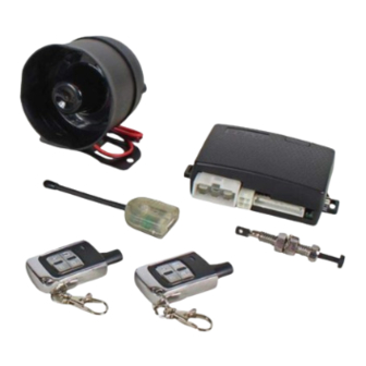
Page 3: Components
INSTALLATION MANUAL REMOTE VEHICLE STARTER Page 3 Components - Control module - 4 Button remote transmitter’s - Antenna with built in - 6 pin main harness with dual - Program Button and LED’s 30 amp power inputs. - Multi-tone Siren - 11 pin harness** - 14 pin harness* - 4 pin harness**... -
Page 4: Installation Procedures
INSTALLATION MANUAL REMOTE VEHICLE STARTER Page 4 Recommended Installation Procedures Proper Connections - Remote Starters can handle loads of up to 30 amps for extended periods of time. It is critical to insure that all high current connections are properly soldered and insulated with quality electrical tape. Failing to insure proper connections will result in warranty being VOID and can result in damage to the vehicle and remote starter module. - Page 5 INSTALLATION MANUAL REMOTE VEHICLE STARTER Page 5 Wiring Diagram - 11 pin + 4 pin Connectors Starter Output 30amp Output YELLOW Heater/Acc Output 30amp Output GREEN 30amp Input Power Input Power Input 30amp Input 30amp Output Selectable Output WHITE 30amp Output Ignition Output BLUE (-)250ma Output...
- Page 6 INSTALLATION MANUAL REMOTE VEHICLE STARTER Page 6 Wiring Diagram 14 pin connector Starter Output YELLOW 30amp Output Heater/Acc Output GREEN 30amp Output Power Input 30amp Input 30amp Input Power Input Selectable Output WHITE 30amp Output 30amp Output Ignition Output BLUE (-)250ma Output Factory Re-arm Output YELLOW...
- Page 7 INSTALLATION MANUAL REMOTE VEHICLE STARTER Page 7 Wiring Diagram auxiliary connectors * The centre pin of the keyless entry harness is not to be used for anything besides plug-in devices such as the VP-1, DL-3, DL-7 and Data Bus Modules. Overloading this output will damage the remote starter.
-
Page 8: Pin Connector
INSTALLATION MANUAL REMOTE VEHICLE STARTER Page 8 6 Pin Power Connector 6-pinDescription Test For Wire 1-Yellow 30amp Starter Output - This wire will test 0volts in off, accessory and in the ignition position.12volts during start only. 2-Green 30amp Heat/Acc Output - This wire will test 0volts in the off position 12- 14volts in the accessory and run positions and 0 volts during start 3-Red 30amp Power Input - 12volts at ignition harness or from battery. -
Page 9: Auxiliary Connectors
INSTALLATION MANUAL REMOTE VEHICLE STARTER Page 9 Auxiliary Connectors continued from previous page 11-Black Ground - System Chassis Ground Input. 12-Blue Glow Plug - Diesel Glow plug input, detects both 12volt and negative glow plug signals. Programmable input. See Menu 3. 13-Blue/White Tach - A/C Tach Signal Input. -
Page 10: Plug-In The Module
INSTALLATION MANUAL REMOTE VEHICLE STARTER Page 10 Step 1 - Connect All Of the Following Wires 6 Pin Power Connector Yellow 30amp Starter Output - 12volts during start position only. Green 30amp Heater Output - 12volts in the accessory position off during start and 12volts during run. -
Page 11: Clutch Bypass
INSTALLATION MANUAL REMOTE VEHICLE STARTER Page 11 Manual Transmission “M” Models Never install an automatic transmission remote starter into a manual transmission vehicle!!! Doing so may result in serious injury or death. Do not install remote starters in convertible vehicles! The following wires must be connected In addition to the basic remote starter installation. -
Page 12: Auto Tach Learn
INSTALLATION MANUAL REMOTE VEHICLE STARTER Page 12 Auto Tach Learn 1) Turn the ignition key to the “ON” position. (The park lights will turn on*). 2) Start the vehicle with the key, The LEDs on the antenna will turn on if a proper tach signal is detected**, then after 30-35 seconds the park lights will flash and the siren will chirp twice to confirm Tach Learn. -
Page 13: Important Tach Notes
INSTALLATION MANUAL REMOTE VEHICLE STARTER Page 13 Important Tach Notes Tach Learning the remote starter is one of the most important steps in the installation process. Do not tach learn vehicle while the engine is in high idle. To ensure the best possible tach setting, ensure that the vehicle is at low idle/ normal operating RPM. -
Page 14: Entering Program Mode
INSTALLATION MANUAL REMOTE VEHICLE STARTER Page 14 Entering Program Mode 1) With the ignition in the OFF position, turn the ignition key from “Off” to “On” 3 times, ON-OFF-ON-OFF-ON within three seconds. (Leave the key in the ON position) 2) Press and release the Program Button located on the antenna. The park lights will flash and the siren will chirp to confirm entering program mode. -
Page 15: Quick View Programming
INSTALLATION MANUAL REMOTE VEHICLE STARTER Page 15 Quick View Programming * See the following pages for more detailed programming instructions. Menu 1 - Press Lock 1 Flash 2 Flashes 3 Flashes 1 Ignition Lock Enabled Lock Only Disabled 2 Siren Chirp Type 1 Type 2 All Chirps... - Page 16 INSTALLATION MANUAL REMOTE VEHICLE STARTER Page 16 Menu 1- User Settings Ignition 3x Press and Press and Press and Press and Ignition ON-OFF-ON-OFF-ON Release the On/Off Release the Release the Hold the Program Switch On/Off On Program lock button for Program Switch Press &...
- Page 17 INSTALLATION MANUAL REMOTE VEHICLE STARTER Page 17 Menu 1- User Settings.. continued from previous page Setting 6 Sensor Enable/Disable 1) Sensor Disabled 1 Flash/Chirp Impact Sensor Disabled *2) Sensor Enabled 2 Flashes/Chirps Impact Sensor Enabled Press & Release the Program Button 6 Times (Setting 6) Confirmed with 6 LED flashes. Press &...
- Page 18 INSTALLATION MANUAL REMOTE VEHICLE STARTER Page 18 Menu 2- Additional Settings ...continued from previous page. Setting 4 (#) Button Operations 1) Trunk Release 1 Flash/chirp # Button activates Trunk Release 2) Garage Door Interface 2 Flashes/chirps # Button activates Garage Door Interface (optional) *3) Car Finder 3 Flashes/chirps # Button activates Car Finder Mode...
- Page 19 INSTALLATION MANUAL REMOTE VEHICLE STARTER Page 19 Menu 3- Starter Settings - Continued From Previous Page Setting 2 With 14pin Connector- Gas/Diesel Mode (Auxiliary Connector Pin 12) 1) (-) Input 1 Flash/chirp (-) Glow Plug input. Waits maximum 30 seconds then starts. 2) Time Delay 2 Flashes/chirps Waits for approximately 15 seconds then remote starts.
- Page 20 INSTALLATION MANUAL REMOTE VEHICLE STARTER Page 20 Menu 4- Tach Settings Press and Ignition 3x Press and Press and Press and Release the On/Off Release the Release the Hold the Program Switch On/Off On Program # button Program Switch 1x =Setting 1 Auto Tach Learn.
-
Page 21: Transmitter Programming
Lock Button On/Off On Program Button Single Car Operation, Program Dual Car, Control 2 Ultra Start up to 4 remote’s vehicles with the same remote Battery Replacement The transmitter battery should be changed at least once every year to maintain proper operating range. - Page 22 INSTALLATION MANUAL REMOTE VEHICLE STARTER Page 22 Negative Type Door Locks 250ma Vehicle Lock To Control Lock/Unlock Relay or Switch Actuators lock Green Blue Negative Door Locks (More Than 250ma) Fused +12V Vehicle Ground Lock/Unlock Lock lock Switch Green Blue To Control Relay or Actuator Positive Type Door Locks...
- Page 23 INSTALLATION MANUAL REMOTE VEHICLE STARTER Page 23 5 Wire / Reverse Polarity Type Door Locks Fused +12V Green Blue Vehicle Lock To Actuator Lock/Unlock Switch lock Aftermarket Doorlock Actuators Ground Vacuum Type Door Locks DIAGNOSTICS Ground Fused +12V Green Blue Lock To Vacuum Pump...
-
Page 24: Diagnostics
INSTALLATION MANUAL REMOTE VEHICLE STARTER Page 24 DIAGNOSTICS If the remote starter does not activate when the start button is pressed the park lights will flash a diagnostic to indicate what shutdown input has been triggered. For example when the start button is pressed the park lights flash 3 times slowly. Looking at the chart below this would indicate that the system is in Service Mode, simply follow the instructions listed in the owners manual on exiting Service Mode and the remote starter will begin to function as normal.
Need help?
Do you have a question about the 22 SERIES and is the answer not in the manual?
Questions and answers