
Subscribe to Our Youtube Channel
Related Manuals for Oakton Temp-340 Thermistor


Summary of Contents for Oakton Temp-340 Thermistor
- Page 1 Instruction Manual INSTRUCTION MANUAL Temp-340 Thermistor ® Oakton Temp-340 Datalogging Thermometer Thermistor Datalogging Thermometer Part of Thermo Fisher Scientific 68X536601 R0 Mar 2010...
-
Page 3: Table Of Contents
TABLE OF CONTENTS 1. INTRODUCTION ........1 2. SAFETY PRECAUTIONS......2 3. SPECIFICATIONS ........3 4. BATTERY INSTALLATION AND REPLACEMENT........6 5. INSERTING AND REMOVING OPTIONAL RUBBER ARMOUR........8 6. ASSEMBLING OPTIONAL HANDSFREE ACCESORIES ........... 9 7. CONNECTING A THERMISTOR .... 10 8. -
Page 4: Introduction
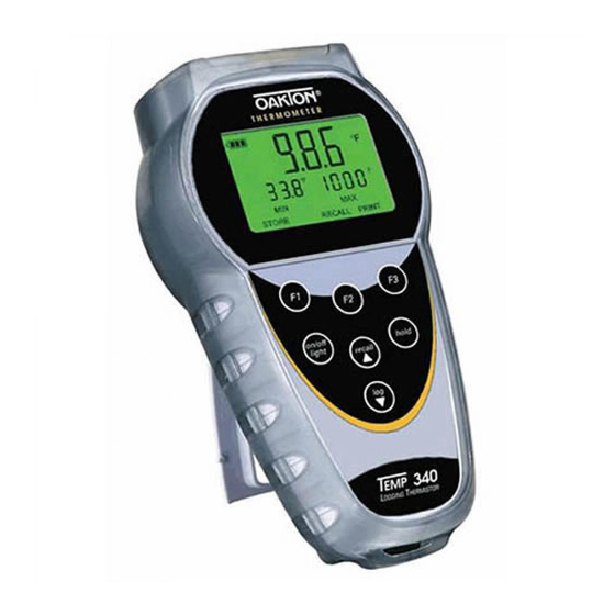
INTRODUCTION This versatile hand-held instrument provides highly accurate temperature measurements. instrument designed for easy operation and includes following features: • Menu driven setup and operation • Datalogging for up to 2000 points • USB output • Operator selection of Celsius or Fahrenheit scale •... -
Page 5: Safety Precautions
SAFETY PRECAUTIONS WARNING: This instrument is designed to accept low level signals supplied by standard Thermistors. Under NO circumstances should input voltage exceed the specified 50V RMS. To prevent ignition of a hazardous atmosphere, batteries must only be changed in an area known to be non-hazardous. -
Page 6: Specifications
SPECIFICATIONS Thermistor Thermometers Type Temperature range -40 to 150°C 400 series (-40 to 302°F) Out of range display: OPEN Resolution 0.01 or 0.1 °F/°C; auto-ranging to 0.1° above +99.99° Accuracy From –40.00 to 99.99°F (–40.00 to 99.99°C): ±0.06°F (±0.03°C), From 100.0 to 257.0°F (100.0 to 125.0°C): ±0.1°F (±0.1°C), From 257.0 to 302.0°F (125.0 to 150.0°C): ±0.9°F (±0.5°C) - Page 7 Auto Off (adjustable time) Enable/Disable option available Stability Criteria Yes, upon stability of 5 seconds Display update rate 0.6 sec per update. Input One bayonet connector . Input Protection 50V rms Storage –40°C to 65°C (–40°F to 149°F) Humidity 10% to 90% (non-condensing) Battery Life Size: Three AA, 1.5V;...
- Page 8 Ingress protection: Meets IEC-529 IP-54 for dust and water resistant enclosures (probe attached) CE Compliance EN61326-1/A1: 1998 (EU EMC Directive) - 5 -...
-
Page 9: Battery Installation And Replacement
BATTERY INSTALLATION AND REPLACEMENT total battery life without backlighting about hours. Remaining battery power is indicated but the battery life indicator. Indicator Voltage Cell + 3 bars More than 4.1 V Cell + 2 bars More than 3.6 V Cell + 1 bars More than 3.0 V Cell + empty More than 2.85 V... - Page 10 Selected settings are stored in memory and will remain in memory even after power is turned off, or while batteries are being replaced. Before changing battery, turn instrument disconnect Thermistor. Loosen screw and lift battery cover off back of case. Remove the three AA batteries.
-
Page 11: Inserting And Removing Optional Rubber Armour
INSERTING AND REMOVING OPTIONAL RUBBER ARMOUR insert thermometer into optional rubber armor, slide in from the top of meter before pushing the bottom edges of meter down to set it into position. Lift up the stand at the back meter bench applications if necessary. -
Page 12: Assembling Optional Handsfree Accesories
ASSEMBLING OPTIONAL HANDSFREE ACCESORIES You can use the optional magnets and strap in the Handsfree Kit accessories for hands free operations. - 9 -... -
Page 13: Connecting A Thermistor
CONNECTING A THERMISTOR Use the correct 400 series Thermistor for your instrument. Using an incorrect probe type will result in erroneous readings. Insert the bayonet plug into the mating connector on the top of the instrument. If no probe is connected the display will read “open”. -
Page 14: Key Functions
KEY FUNCTIONS Step through Min, Max and Avg readings. Toggle between F and C display Toggle between menu and measure mode hold Freeze display Turns meter on and off (press and hold for 3 seconds to turn on/off off) light Press momentarily to turn on backlight Recalls and steps through... -
Page 15: Display Overview
DISPLAY OVERVIEW The dot matrix display features a large primary display, smaller secondary displays for channel info or min/max/ave, helpful annuciators added measurement data - 12 -... - Page 16 Power supply indicator (Battery/Main adaptor/USB) Date (format of mmm – dd) Time (hour:min Time format (am/pm/hrs) Measurement mode Hold function indicator Stable indicator Data logging indicator PC data logging indicator Main reading display Current reading unit indicator Min/Max/Avg elapsed time Current Min/Max/Avg reading indicator Meter logging memory location...
-
Page 17: Measurement Mode
10. MEASUREMENT MODE On initial start-up the meter will display the measured value for in the primary display. Pressing the F2 key will toggle reading between F and C display. Pressing the F1 key initiates and toggles through Minimum, Maximum, Average reading modes. -
Page 18: Hold Functon
11. HOLD FUNCTON Press the hold key to retain the reading on the display. Press the hold key again for normal operation. 12. MIN, MAX, and AVE FUNCTION Press the F1 key to toggle between the minimum, maximum, average readings. The minimum and maximum reading function is ideal for monitoring unattended operations while continually displaying every temperature change that... -
Page 19: Setup Mode
14. SETUP MODE access setup mode from measurement mode press the F3 key (Menu). Press ▲▼ keys on the meter key pad to scroll through options. To enter a setup screen press Select F1 key. To return to measurement mode press Meas F3 key. -
Page 20: General Setup Screen
15. GENERAL SETUP SCREEN The first page of the General Setup screens let you set Resolution, auto-off time, and password. Press F1 to indicate you want to change the setting of the current parameter or recall▲ or log▼ to move to the next parameter. - Page 21 This screen below is used to reset/change password. In the event if uses forget his/her password, 5586 can be used to eset to a new value On the second page you can set time and date. - 18 -...
-
Page 22: Calibration Screen
16. CALIBRATION SCREEN The thermometer is factory calibrated and does not require calibration before use. The Calibration function allows single point calibration of the thermometer, at any temperature point to compensate for Thermistor off-set error. necessary to perform a field calibration to obtain specified meter accuracy. - Page 23 There are two calibration options: Offset - adjusts at a single point. Offset calibration can be performed at any temperature in the offset range of ±5.00 °C or 9.00 °F Slope – adjusts at two points. The two calibration points must be at least 20.00 °C (36.00 °F) apart.
-
Page 24: Alarms Screen
17. ALARMS SCREEN There are two kind of alarm setting is available under the alarm setting options Measurement alarm Disable or enable the alarm by pressing recall▲ or log▼and F1 to accept. Increase or decrease individual limit by pressing recall▲ or log▼. Meter in alarm mode - 21 -... - Page 25 Countdown alarm You can enable/disable the countdown alarm and set the countdown time from 5 sec to 1 hour. After setting (enabling) the countdown alarm, the measurement screen should look like this: - 22 -...
- Page 26 Press F2 key to start the countdown: Press F2 key in the middle of a countdown will stop the process: You will need to restart the countdown by selecting the “start” key (F2). Alternatively, you can also choose “Menu” to go into the timer menu and disabling the alarm.
- Page 27 The buzzer will sound for 30 seconds, or until the reset (F2) is pressed, at the end of the countdown. Flashing announciator indicates that the countdown has expired To reset the timer, select “restart” (F2) it. You display should look like this: To repeat the functions, select F2 Note: The °C/ °F function is disabled when the...
- Page 28 “Alarm Setting page 2” and disable the count down alarm function. When activated, the countdown timer temporarily over-rides the Auto-shutoff until the countdown is completed or manually stopped. If the meter is manually or auto shutoff, The Countdown Alarm is automatically reset to “Disable”...
-
Page 29: Data Logging Screen
18. DATA LOGGING SCREEN Press recall▲ or log▼to choose the logging methods as auto or manual. If it is auto logging, using recall▲ or log▼to set time interval. Its range is from 0min to 60min. Data Transfer from Meter to Computer Once the USB connection is establish with - 26 -... -
Page 30: Calibration Report Screen
PC, press the Start button to download data from Meter using HyperTerminal. ***NOTE: METER MUST BE TURNED ON PRIOR TO CONNECTING USB CABLE OR COMPUTER MAY NOT RECOGNIZE THE INSTRUMENT*** 19. CALIBRATION REPORT SCREEN The Calibration report will show the time and date along with results of the last user calibration. -
Page 31: Clear / Reset Screen
20. CLEAR / RESET SCREEN Press F1 to choose which data you want to clear or reset. For calibration, logged data and reset all, you will have to enter password proceed. (Default Password is 9900) - 28 -... -
Page 32: Maintenance
21. MAINTENANCE Properly used, the thermometer should maintain calibration indefinitely and not require service other than occasional cleaning of the housing and changing of the batteries. 22. CLEANING WARNING: TO PREVENT IGNITION OF A HAZARDOUS ATMOSPHERE BY ELECTROSTATIC DISCHARGE, CLEAN WITH DAMP CLOTH. Do not clean with abrasives or solvents. -
Page 33: Trouble Shooting
Cannot connecting to USB port. Before and connect after the driver is installed, your PC to PC may not recognize the Temp-340 if the Temp-340 is not powered on prior to connecting the USB to the computer. - 30 -... -
Page 34: Accessories
25. ACCESSORIES Replacement Meters Meter Accessories Item Part Number Temp 340 thermometer 35426-50 91426-50 Rubber Armour with Stand 35427-80 Hands-free Kit (Two magnets and a 35427-85 strap) General Purpose Probe (Immersion 08491-06 into liquids) Flexible General Purpose Probe 08491-02 (Vinyl sheath) USB cable 35427-86 Adapter, 115 VAC... -
Page 35: Warranty
26. WARRANTY The Manufacturer warrants this product to be free from significant deviations from published specifications for a period of three years. If repair or adjustment is necessary within the warranty period, the problem will corrected at no charge if it is not due to misuse or abuse on your part determined by the Manufacturer. -
Page 36: Innocal® Calibration And Repair Services
28. INNOCAL® CALIBRATION AND REPAIR SERVICES Optimum performance your temperature-measuring instrument not a timeless condition. To ensure quality measurements, have your instrument calibrated regularly. Trust InnoCal® to satisfy your calibration and equipment repair needs. With over a decade service, we've helped thousands of customers meet ISO, FDA, EPA, GLPs/cGMPs and other quality... - Page 37 Reliable Support Trust in our free diagnostic support and troubleshooting advice. Our factory- trained metrologists and technicians are armed with years of experience and extensive technical data. Convenient Reminders It’s so easy to keep your instruments functioning properly. Based on your requirements, InnoCal will send you a reminder when it’s time to re-certify or service your instrument.
- Page 38 as ISO 9000, certification is becoming increasingly important. Traceability is not a timeless condition. It must be verified and maintained over the life of the calibration to ensure the highest accuracy possible. When you have your calibration done by InnoCal, we will send you an automatic reminder when it is time to recalibrate your instrument.
- Page 39 Calibration test points System against Meter Probe (meter + NIST- only only probe)* traceable standards Four test points across range of instrument. 17000-06 17001-06 17002-06 0, 100, 165, 230 C (-4, 32, 446, 770F) InnoCal—The Choice of Quality 866-InnoCal (866-466-6225) InnoCalSolutions.com - 36 -...
- Page 41 TECHNICAL ASSISTANCE If you have any questions about the use of this product, contact the Manufacturer or authorized seller. For more information on OAKTON Instruments Products, please contact your nearest distributor or visit our web site listed below: Oakton Instruments...
Need help?
Do you have a question about the Temp-340 Thermistor and is the answer not in the manual?
Questions and answers