ADTRAN Total Access 908e Hardware Installation Manual
Total access 900e series
Hide thumbs
Also See for Total Access 908e:
- Quick reference manual (2 pages) ,
- Specifications (4 pages) ,
- Hardware installation manual (34 pages)

Related Manuals for ADTRAN Total Access 908e


Summary of Contents for ADTRAN Total Access 908e
- Page 1 Total Access 900e Series Hardware Installation Guide Total Access 908e Total Access 916e Total Access 924e 64243916F1-34A August 2013...
- Page 2 Total Access® is a registered trademark of ADTRAN, Inc. To the Holder of the Manual The contents of this manual are current as of the date of publication. ADTRAN reserves the right to change the contents without prior notice. In no event will ADTRAN be liable for any special, incidental, or consequential damages or for commercial losses even if ADTRAN has been advised thereof as a result of issue of this publication.
- Page 3 Total Access 900e Series Hardware Installation Guide Conventions Conventions Notes provide additional useful information. Cautions signify information that could prevent service interruption or damage to the equipment. Warnings provide information that could prevent injury or endangerment to human life. 64243916F1-34A Copyright © 2013 ADTRAN, Inc.
- Page 4 These units contain no user-serviceable parts. They should only be serviced by qualified service personnel. Additional safety guidelines, such as Waste Electrical and Electronic Equipment (WEEE), are given in the document NetVanta Safety and Regulatory Information available online at http://supportforums.adtran.com. Save These Important Safety Instructions Copyright © 2013 ADTRAN, Inc. 64243916F1-34A...
- Page 5 Advance notification and the opportunity to maintain uninterrupted service are given. 4. If experiencing difficulty with this equipment, please contact ADTRAN for repair and warranty information. The telephone company may require this equipment to be disconnected from the network until the problem is corrected, or it is certain the equipment is not malfunctioning.
- Page 6 Denial of Service (DoS) attacks, loss or theft of data, and the unauthorized or illegal use of said equipment. ADTRAN OFFERS NO WARRANTIES, EITHER EXPRESSED OR IMPLIED, REGARDING THE PREVENTION, DETECTION, OR DETERRENCE OF TOLL FRAUD, NETWORKING ATTACKS, OR UNAUTHORIZED, ILLEGAL, OR IMPROPER USE OF ADTRAN EQUIPMENT OR SOFTWARE.
-
Page 7: Table Of Contents
Wall Mounting the Total Access 908e BBU (1200641L1) ....... . . - Page 8 Table of Contents Total Access 900e Series Hardware Installation Guide Copyright © 2013 ADTRAN, Inc. 64243916F1-34A...
- Page 9 Total Access 908e Rear Panel Layout........
- Page 10 List of Figures Total Access 900e Series Hardware Installation Guide Copyright © 2013 ADTRAN, Inc. 64243916F1-34A...
- Page 11 Table A-6. CRAFT Port Pinouts............33 64243916F1-34A Copyright © 2013 ADTRAN, Inc.
- Page 12 List of Tables Total Access 900e Series Hardware Installation Guide Copyright © 2013 ADTRAN, Inc. 64243916F1-34A...
-
Page 13: Introduction
For information on Total Access 900e Series configuration for a specific application, refer to the configuration guides provided on the ADTRAN Support Community. For details on the command line interface (CLI), refer to AOS Command Reference Guide. All other related documents are also available online at http://supportforums.adtran.com. 64243916F1-34A Copyright © 2010 ADTRAN, Inc. -
Page 14: Physical Description
VoIP network. The last two digits of the product name indicate the number of on-board FXS ports. The Total Access 908e contains 8 FXS ports, the Total Access 916e contains 16 FXS ports, and the Total Access 924e contains 24 FXS ports or 16 FXS ports plus 8 FXO ports with octal FXO daughterboard. -
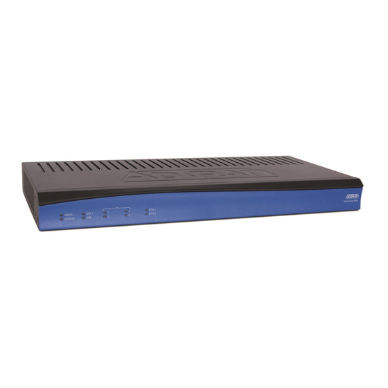
Page 15: Reviewing The Front Panel Design
LEDs. Reviewing the Rear Panel Design Total Access 908e Rear Panel Interfaces Figure 2 shows the Total Access 908e product’s rear panel, which contains identical interfaces regardless of the model. ETH 0/1 AC INPUT VOICE... - Page 16 The rear panel has a power input to a 120 VAC power supply with an IEC connector. The appropriate three-prong cable is included in the shipment. Refer to Supplying Power to the Unit on page 25 connection details. Copyright © 2010 ADTRAN, Inc. 64243916F1-34A...
-
Page 17: Total Access 916E And Total Access 924E Rear Panel Interfaces
EIA-232 serial port (DCE) that provides for local management and CRAFT configuration (using a DB-9 female connector). Table A-6 on page 33 shows the CRAFT port pinouts. Connection directly to an external modem requires a cross-over cable. 64243916F1-34A Copyright © 2010 ADTRAN, Inc. - Page 18 The rear panel has a power input to a 120 VAC power supply with an IEC connector. The appropriate three-prong cable is included in the shipment. Refer to Supplying Power to the Unit on page 25 connection details. Copyright © 2010 ADTRAN, Inc. 64243916F1-34A...
-
Page 19: Led Descriptions
Alarm or fault condition is occurring on the port interface. ETH 1/ETH 2 LAN is administratively disabled or link is down. Green (solid) The link is up. Amber (flashing) There is activity on the link. 64243916F1-34A Copyright © 2010 ADTRAN, Inc. -
Page 20: Product Specifications
SNMP • LEDs for system status information • Chassis dimensions (Total Access 908e): 1.75-inch H x 17.0-inch W x 8.0-inch D • Chassis dimensions (Total Access 916e/924e): 1.75-inch H x 17.0-inch W x 8.0-inch D • AC power: 120 VAC, 60 Hz •... -
Page 21: Unit Installation
ADTRAN unit to Ethernet cables that run outside the building, ADTRAN's Ethernet Port Protection Device (EPPD) (P/N 1700502G1) must be connected between the unit and the outside plant cable. Use of any Ethernet protector other than ADTRAN's for this purpose will void the user's warranty. -
Page 22: Mounting Options
Have an assistant hold the unit in position as you install two #6 to #10 (1-inch or greater in length) wood screws through the unit’s brackets and into the mounted board (see Figure 4 on page 23). Proceed to the steps given in Grounding Instructions on page Copyright © 2010 ADTRAN, Inc. 64243916F1-34A... -
Page 23: Rack Mounting Total Access 900E Series
The Total Access 900e Series products mount and connect with standard fasteners and hand tools. ADTRAN recommends 1U (1.75 inches) of separation above and below the Total Access 900e Series unit. This spacing allows the unit to dissipate heat. The design of the Total Access 900e Series uses the chassis to distribute heat generated by the unit’s... -
Page 24: Grounding Instructions
Copyright © 2010 ADTRAN, Inc. 64243916F1-34A... -
Page 25: Grounding For Ac Power
• A readily accessible disconnect device, that is suitably approved and rated, shall be incorporated in the field wiring. ° • Maximum recommended ambient operating temperature is 50 64243916F1-34A Copyright © 2010 ADTRAN, Inc. -
Page 26: Battery Backup Unit
Battery Backup Unit Total Access 900e Series Hardware Installation Guide BATTERY BACKUP UNIT The ADTRAN battery backup unit (BBU) is an optional device designed as a backup DC power supply for the Total Access 900e Series. Total Access 908e BBU (P/N 1200641L1) The BBU connects to the Total Access 908e through a 2-foot charge/discharge, 2-conductor wire with a keyed modular plug (included with the BBU). -
Page 27: Bbu Safety Notices
• This device must accept any interference received, including that which may cause undesired operation. Wall Mounting the BBU Wall Mounting the Total Access 908e BBU (1200641L1) Figure 5 shows the BBU mounting dimensions for the Total Access 908e. TOP of Unit 2.734 " edge-to-center 4.280 "... -
Page 28: Wall Mounting The Total Access 916E/924E Bbu (1175044L1/L2)
For a wallmount installation, the BBU installs on heavy plywood (3/4-inch minimum) using two #10 x 3/4-inch pan-head wood screws. Install the BBU as follows: Figure 6 shows the BBU mounting dimensions for the Total Access 916e/924e. Figure 6. Wall Mounting the 1175044L1/L2 BBU Copyright © 2010 ADTRAN, Inc. 64243916F1-34A... -
Page 29: Maintenance
To order replacement batteries, reference the following part number: 1975044L1 (12 V replacement batteries). ADTRAN is an environmentally friendly company. Therefore, we encourage the proper recycling and handling of the batteries. Federal and state laws prohibit the improper disposal of all lead acid batteries. -
Page 30: Specifications
ADTRAN’s Support Forum For details on the CLI, refer to the AOS Command Reference Guide. All other related documents are also available online on ADTRAN’s Support Forum. Copyright © 2010 ADTRAN, Inc. 64243916F1-34A... -
Page 31: Appendix A. Pin Assignments
23, 48 Circuit 23 FXS 0/23 Ring, Tip or FXO 0/7 Ring, Tip 24, 49 Circuit 24 FXS 0/24 Ring, Tip or FXO 0/8 Ring, Tip 25, 50 FXO 0/0 FXO 0/0 Ring, Tip 64243916F1-34A Copyright © 2013 ADTRAN, Inc. -
Page 32: Table A-2. Fxo 0/0 Pinouts
Transmit data toward the network (Tip) — Unused Table A-4. 10/100Base-T (ETH 0/1 through ETH 0/2) Pinouts Name Description Transmit Positive Transmit Negative Receive Positive 4, 5 — Unused Receive Negative 7, 8 — Unused Copyright © 2013 ADTRAN, Inc. 64243916F1-34A... -
Page 33: Table A-5. 1000Base-T Gigabit Ethernet Port Pinouts
Ground - connected to unit chassis Data Set Ready (output) Request To Send - flow control (input) Clear To Send - flow control (output) — Not Connected Connection directly to an external modem requires a cross-over cable. 64243916F1-34A Copyright © 2013 ADTRAN, Inc. - Page 34 Appendix A Total Access 900e Hardware Installation Guide Copyright © 2013 ADTRAN, Inc. 64243916F1-34A...
Need help?
Do you have a question about the Total Access 908e and is the answer not in the manual?
Questions and answers