
Subscribe to Our Youtube Channel
Related Manuals for Minicom 0SU51068


Summary of Contents for Minicom 0SU51068
-
Page 1: User Guide
Smart IP Access User Guide 1111 W. 35th Street, Chicago, IL 60609 USA www.tripplite.com/support Copyright ©2012 Tripp Lite. All rights reserved. -
Page 2: Table Of Contents
SMART IP ACCESS Table of Contents 1. Welcome ......................3 2. Introduction ......................4 3. Key Features ....................... 4 4. System components................... 4 5. The Smart IP Access unit................... 5 6. Pre-installation guidelines ................. 6 6.1 Avoiding general rack mounting problems .............6 6.2 Rack mounting the IP Access...................7 7. - Page 3 USER GUIDE 24. Starting a remote session ................22 24.1 Taking over a busy remote session ..............23 24.2 Full screen mode ....................23 24.3 Moving or hiding the Toolbar................24 24.4 Switching to a different server/device ..............24 24.5 Changing the performance settings..............25 24.6 Adjusting the Video settings.................26 24.6.1 Refresh ......................26 24.6.2 Manual Video Adjust ..................26...
-
Page 4: Welcome
SMART IP ACCESS 1. Welcome Thank you for buying the Smart IP Access system. This system is produced by Minicom Advanced Systems Limited. This document provides installation and operation instructions for Minicom’s Smart IP Access. It is intended for system administrators and network managers, and assumes that readers have a general understanding of networks, hardware and software. -
Page 5: Introduction
USER GUIDE 2. Introduction The Smart IP Access extends your KVM (keyboard, video, mouse) from any computer or server over TCP/IP via LAN, or WAN. Now you can control, monitor and manage your servers from wherever you are, inside or outside the organization. The Smart IP Access is a cost-effective hardware solution, for secure remote KVM access &... -
Page 6: The Smart Ip Access Unit
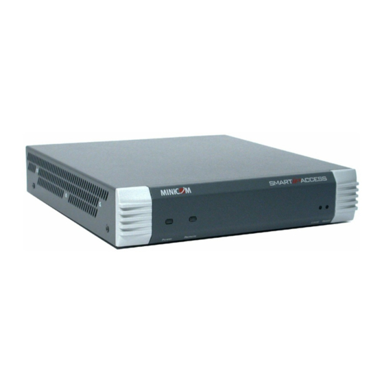
SMART IP ACCESS RS232 Cross cable option Smart IP Access has two RS232 RJ45 connectors. You can purchase another RS232 Cross cable to connect a second Serial device. P/N 5CB00566 5. The Smart IP Access unit Figure 1 illustrates the front panel of the Smart IP Access. MINICOM SMARTIPACCESS Power... -
Page 7: Pre-Installation Guidelines
USER GUIDE The figure below illustrates the rear panel of the Smart IP Access. SERIAL 1 and 2 Computer RS232 Monitor Video card connectors www.minicom.com CONSOLE COMPUTER POWER 100-240 VAC 50/60 Hz Computer Mouse Mouse port Power LAN 1 and 2 Computer Keyboard connector... -
Page 8: Rack Mounting The Ip Access
SMART IP ACCESS Reduced airflow Install the equipment in a rack in such a way that the amount of airflow required for safe operation is not compromised. Leave a gap of at least 5cm/2” each side of the Smart IP Access. Mechanical loading Mount the equipment in the rack in such a way that a hazardous condition is not achieved due to uneven mechanical loading. -
Page 9: Client Computer Operating System
USER GUIDE 8. Client computer operating system Windows NT4.0, 2000, XP or 2003 Server, with IE 6.0 or higher. 128 bit encryption is required if a secured connection is selected. 9. Connecting the system Connect the Target Server / KVM switch to the Smart IP Access as follows: 1. - Page 10 SMART IP ACCESS 3 in 1 CPU cable A u t o h p 1 9 2 5 www.minicom.com Target PC CONSOLE COMPUTER POWER 100-240 VAC 50/60 Hz LAN / WAN User over IP Figure 4 Smart IP Access connections to a computer...
-
Page 11: Default Ip Address
USER GUIDE KVM switch SERIAL MOUSE STATION 2 COMPUTER 5 COMPUTER 6 COMPUTER 7 COMPUTER 8 POWER PS/2 MOUSE SCREEN COMPUTER 1 COMPUTER 2 COMPUTER 3 COMPUTER 4 3 in 1 CPU cable A u t o h p 1 9 2 5 ProLiant D L360 9. -
Page 12: Logging Into The Web Interface
SMART IP ACCESS 11. Logging into the Web interface To complete the initial setup via the Web configuration interface: 1. Open your Web browser (Internet Explorer version 6.0 or higher) 2. Type the IP address of the Smart IP Access system - https://IP address/config and press Enter. -
Page 13: Ssl Certificate Notes
USER GUIDE 11.1 SSL Certificate notes Upon first connection to Smart IP Access’s https Configuration page, 2 browser security warnings appear. Click Yes to proceed. The first warning disappears upon first Smart IP Access client installation, once Minicom’s root certificate is installed. 12. -
Page 14: Kvm.net
SMART IP ACCESS Enable Access for Configuration - Click to enable access to the configuration menu from the LAN 1. If disabled, a remote session can only be performed via LAN 1 and the Web configuration menu can only be accessed from LAN 2. This may be useful when dedicating LAN 2 to LAN access only, to enhance security. -
Page 15: Administration > User Settings
USER GUIDE 14. Administration > User Settings From the menu click User Settings, the following appears. Figure 9 User Settings On this page an Administrator creates and edits users. There are 3 levels of user access. Administrator User ... -
Page 16: Adding A User
SMART IP ACCESS 14.4 Adding a user To add a user: 1. Click and type a name and a password. The password must be at least 6 characters – letters or numbers, and must not include the user name, even if other characters are added. -
Page 17: Editing A User
USER GUIDE 14.5 Editing a user To edit a user: 1. Select the user from the list. 2. Click . You can now change all the parameters – user name, permission and password. 3. Click , the changes are saved. 14.6 Deleting a user To delete a user: 1. -
Page 18: Administration > Serial Settings
SMART IP ACCESS Figure 10 Switch configuration 1. Choose the manufacturer and model of the connected KVM switch. The number of possible connected servers appears in the Server Name section. 2. Change the name of the connected servers by selecting the server and typing a new name. -
Page 19: Show
USER GUIDE Figure 11 Serial Settings For both Serial ports (where relevant), type in a device name and choose the correct device parameters. 16.1 Show Tick Show to make the device appear in the list of servers/devices that can be accessed. -
Page 20: Security > Ssl Certificates
SMART IP ACCESS The security page elements: Account Blocking – decide on the number of attempts to login with a wrong username or password after which there is a time lock or a total block. Password Policy – You have the option of a standard or high security level of password. -
Page 21: Security > Event Log
USER GUIDE 19. Security > Event Log From the menu select Event Log. The Event Log page appears, see Figure 14. Here you can view the device log, recording various events: security alerts, system alerts, configuration changes, and user activity. Figure 14 Event log 20. -
Page 22: Maintenance > Firmware Upgrade
SMART IP ACCESS 21. Maintenance > Firmware Upgrade Upgrade the Smart IP Access firmware to take advantage of new features. You can receive firmware updates by email or download them from the Minicom Web site. Save the firmware file on the Client computer. From the menu select Firmware Upgrade. -
Page 23: Saving Changes And Logging Out
USER GUIDE Figure 17 Restore factory settings 2. Click 23. Saving changes and logging out To save any configuration changes and restart the IP Access click To exit the configuration menu and close the session click Only one Administrator can log into the configuration area at a time. An idle timeout of 30 minutes terminates the session. -
Page 24: Taking Over A Busy Remote Session
SMART IP ACCESS Figure 18 Remote session window 24.1 Taking over a busy remote session When connecting to a busy Target Server an Administrator has the option to take over the Target Server. A User only has this option when the current session is run by another User, but not by an Administrator. -
Page 25: Moving Or Hiding The Toolbar
USER GUIDE 3. Right click the Internet Explorer menu bar and check Auto-Hide. The Internet Explorer menu bar disappears. You are in full screen mode. To exit full screen mode: Press F11. Or place the mouse at the top of the window to display the Internet Explorer toolbar and click the Restore button. -
Page 26: Changing The Performance Settings
SMART IP ACCESS 24.5 Changing the performance settings You can alter the bandwidth settings from the Toolbar. To alter the settings: From the Toolbar, click . The Settings.. box appears, see Figure 20. Figure 20 Settings.. box Bandwidth Choose from the following options Adaptive –... -
Page 27: Adjusting The Video Settings
USER GUIDE 24.6 Adjusting the Video settings To change the video settings: From the Toolbar, click . You have the following options: Refresh Manual Video Adjust Auto Video Adjust Each option is explained below. 24.6.1 Refresh Select Refresh or press Ctrl+R to refresh the Video image. Refresh may be needed when changing the display attributes of a Target Server. -
Page 28: Auto Video Adjust
SMART IP ACCESS 2. Move the sliders to change the displayed image. Click in the area of the sliders for fine-tuning. Brightness / Contrast - use the scales to adjust the brightness and contrast of the displayed image. Horizontal Offset - defines the starting position of each line on the displayed image. - Page 29 USER GUIDE Figure 22 Special Key Manager box To add a predefined sequence: 1. Click Add Predefined. A list of sequences appears. 2. Select the desired sequence and click OK. The sequence appears in the Special Key Manager box. 3. Click OK. The sequence appears in the Keyboard Key sequence list. To record a key sequence: 1.
-
Page 30: Synchronizing Mouse Pointers
SMART IP ACCESS To edit a key sequence: 1. From the Special Key Manager box select the desired key. 2. Click Edit. 3. Click Start Recording 4. Press the desired keys. The keys appear in the area provided. 5. Click Stop Recording. 6. -
Page 31: Manual Mice Synchronization
USER GUIDE Note! If the mouse settings on the Target Server were ever changed, you must synchronize mouse pointers manually, as explained below. 24.9.3 Manual mice synchronization If the mouse settings on the Target Server were ever changed, or when the Operating system on the Target Server is, Windows XP / 2003 Server / Vista, Linux, Novell, SCO UNIX or SUN Solaris you must synchronize the mouse pointers manually. -
Page 32: Minicom Logo Menu Features
SMART IP ACCESS The USB option in Mouse Settings box is available for RICC and X-RICC USB and Phantom Specter USB and for unsupported operating systems and SUN Solaris. Use this option if you are sure of the custom acceleration algorithm you are using, or have been informed so by customer support. -
Page 33: Disconnecting The Remote Session
USER GUIDE About - Click About to verify the Client, Firmware, KME (Keyboard/Mouse Emulation firmware) and Switch file versions installed on your Smart IP Access. Local Settings – Click Local settings, the Client Configuration box appears, see Figure 26 Figure 26 Client Configuration box Pointer type –... - Page 34 SMART IP ACCESS 5. Wait 2 minutes until the unit finishes booting. 6. Connect the lower network interface (LAN 2) to the network, and login with the default IP address of the unit: http://192.168.0.155/config. The Login box appears see Figure 27. Figure 27 Login box 7.
- Page 35 USER GUIDE 11.Wait for 2 minutes and then type the default configuration IP address of the unit: https://192.168.0.155/config into your web browser. The Login page appears as in Figure 6 on page 11. 12.Type the default Administrator user name and password. Username: admin, password: access.
-
Page 36: Technical Specifications
SMART IP ACCESS 26. Technical Specifications Target Server Windows 3.1, 9X, 2000, XP, NT4, 2003 Server, Vista. DOS, Novell 3.12 – 6, Linux Operating systems Client Computer Windows NT4.0, 2000, XP or 2003 Server, with IE 6.0 or higher Target Server Up to 1600x1200 @85Hz Resolution Client Computer... -
Page 37: Video Resolution And Refresh Rates
USER GUIDE 27. Video Resolution and Refresh Rates → 640x480 720x400 800x600 1024x768 1152x864 1152x900 1280x720 1280x768 1280x960 1280x1024 1600x1200 28. Safety The device must only be opened by an authorized Minicom technician. Disconnect device from AC mains before service operation! Caution Risk of explosion if battery is replaced by an incorrect type. -
Page 38: Weee Compliance
SMART IP ACCESS 29. WEEE Compliance WEEE Information for Minicom Customers and Recyclers Under the Waste Electrical and Electronic Equipment (WEEE) Directive and implementing regulations, when customers buy new electrical and electronic equipment from Minicom they are entitled to: Send old equipment for recycling on a one-for-one, like-for-like basis (this varies depending on the country) ... - Page 39 USER GUIDE 201204206 • 933197_EN...
Need help?
Do you have a question about the 0SU51068 and is the answer not in the manual?
Questions and answers