
Related Manuals for Minicom 0SU70033


Summary of Contents for Minicom 0SU70033
-
Page 1: User Guide
PX Serial User Guide 1111 W. 35th Street, Chicago, IL 60609 USA www.tripplite.com/support Copyright ©2012 Tripp Lite. All rights reserved. -
Page 2: Table Of Contents
PX SERIAL Table of Contents Welcome ........................2 Introduction ........................3 Integration into KVM.net ......................3 The PX Serial components...................3 PX Serial ports.......................4 PX Serial LEDs ......................5 Mounting the PX Serial ....................5 Connecting the PX Serial .....................5 Connecting the Power supply ....................5 7.1.1 Terminal Block (PWR1)...................... -
Page 3: Welcome
USER GUIDE Welcome Thank you for buying the system. This system is produced by Minicom PX Serial Advanced Systems Limited. This document provides installation and operation instructions for Minicom’s PX Serial. It is intended for system administrators and network managers, and assumes that readers have a general understanding of networks, hardware and software. -
Page 4: Introduction
PX SERIAL 2. Introduction PX Serial is a one-port RS232/422/485 to Redundant Ethernet device server. PX Serial can be configured by a web browser in https, or SSH console. Additional management features include SNMP support and email alerts. 2.1 Integration into KVM.net PX Serial can be integrated in the KVM.net system and managed by the KVM.net. -
Page 5: Px Serial Ports
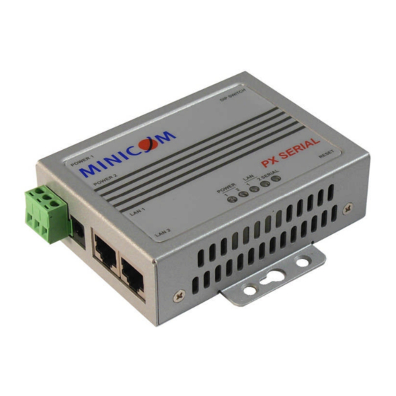
USER GUIDE 4. PX Serial ports Hardware reset button Long distance RS422 /485 120 Ohm termination dipswitches RS232/422/482 port, DB9M 15KV ESD for all signals Speed:110 bps to 460.8kbps Figure 1 PX Serial ports side 9-30 VDC Power Jack Redundant Dual 10/100M Ethernet 12-48 VDC Terminal Auto MDI/MDIX Auto- Block... -
Page 6: Px Serial Leds
PX SERIAL 5. PX Serial LEDs Color Indication PWR 1 On: Power 1 is on and booting up. Blinking: Indicates an IP conflict, or DHCP or BOOTP server did not respond properly. Green On: Power is on and functioning normally. Blinking: Located by Administrator’s Location function. -
Page 7: Terminal Block (Pwr1)
USER GUIDE 7.1.1 Terminal Block (PWR1) 1. Insert the positive and negative wires of your DC supply into the V+ and V- contacts of the terminal block connector – see below. (GND / V- / V+) 2. Tighten the terminal screws to prevent the DC wires from coming loose – see below. -
Page 8: Connecting To The Serial Device
PX SERIAL 7.3 Connecting to the Serial device Connect the Serial device to the DB9M port. The DB9M pin-out appears below. Standard DB9M connector - Pin # RS232 RS422 RS485 (4 wire) RS485(2 wire) RXD- RXD- RXD+ RXD+ TXD+ TXD+ DATA+ TXD- TXD-... -
Page 9: Configuring The Px Serial Unit
USER GUIDE 9. Configuring the PX Serial unit The PX Serial unit can be managed by a Web interface, providing secure SSL communication over the internet. The PX Serial comes with the default IP address 192.169.10.2 - this appears on the underside of the PX unit. To display the Web interface: 1. -
Page 10: Basic Settings
PX SERIAL 9.1 Basic settings Click Basic Setting, the following appears. Figure 4 Basic Setting On this page configure: The server name connected to the PX Time Server settings You can disable the Telnet console e.g. to block access to the device for maintenance purposes. -
Page 11: Network Setting
USER GUIDE 9.2 Network Setting Consult your Network Administrator for the network settings. Click Network Setting, the following appears. Figure 5 Network Setting On this page you configure for the PX: IP Configuration – DHCP or static IP address ... -
Page 12: Port Configuration
PX SERIAL Figure 6 Change password 2. Type a password in the fields. Do not use spaces between the characters. Port Configuration Port Configuration covers Serial Parameter settings, such as baud rate, data bits, stop bits, parity, and flow control. From the menu click Port Configuration to display a sub-menu. -
Page 13: Port Profile
USER GUIDE Select the Interface: RS232 / RS422 / RS485 (2-wires) / RS485(4-wires) Select the settings for Baud rate, Data Bits, Stop Bits, Parity and Flow Control. Force TX interval time is to specify a timeout when no data has been transmitted. When the timeout is reached or TX buffer is full (4K Bytes), the queued data will be sent. -
Page 14: Service Mode
PX SERIAL 10.3 Service Mode Click Service Mode, the following appears. Figure 9 Service Mode In TCP Server mode, you must define the available port number, idle timeout, alive check, and maximum number (between 1 and 5) of simultaneous connections allowed to the web configuration pages. -
Page 15: Management
USER GUIDE Management From the menu click Management to display a sub-menu. 11.1 IP filtering Click IP filtering, the following appears. Figure 10 Access IP Setting The Access IP Setting table specifies the IP address and subnet that can access the device. -
Page 16: Email And Snmp Trap Notification
PX SERIAL 11.2 Email and SNMP Trap Notification Click Email and SNMP Trap, the following appears. Figure 11 Email and SNMP Trap Email Server configuration includes the mail server’s IP address or domain. If authentication is required, specify the username and password. There are 4 email addresses you can specify to receive the notification. -
Page 17: Event Notification
USER GUIDE 11.3 Event Notification Click Event Notification, the following appears. Figure 12 Device Notification: Specify the events that should be notified to the administrator. The events can be notified by means of email, SNMP traps, or system logs. Port Notification: DCD changed: When DCD (Data Carrier Detect) signal changes, indicating the modem connection status has changed, the event will be triggered. -
Page 18: Saving Configuration Changes
PX SERIAL Saving configuration changes To save any configuration changes, click Submit. 12.1 Maintenance Click Maintenance, the following appears. Figure 13 Maintenance From the Maintenance page you can do the following: Load Factory Default: Load default configuration except Network Settings. Import Configuration: Retrieve saved configuration files to apply to the device. - Page 19 USER GUIDE Figure 14 PuTTY Configuration Type the Host Name or IP Address of your PX (default:192.168.10.2). The Port number is the default - 22. For Connection type, choose SSH. Click Open to start the SSH session console. The SSH console appears, see figure below.
-
Page 20: Operating The Device
PX SERIAL Figure 16 PX Serial Commander Configure the device and port by pressing the desired function number or letter. Press “q” to exit the function. Note! Press “a” to apply and save changes. The configuration settings are the same as set out above for configuration via the web. - Page 21 USER GUIDE Connection from PuTTY: [IP address] [Port No.]. Figure 18 PuTTY Connection from Tera Term Web: [IP address] [Port No.]. Figure 19 Tera Term Web Once connected operate the Serial device according to the device’s instructions.
-
Page 22: Snmp Mib Ii Support
PX SERIAL SNMP MIB II support PX has a built-in SNMP agent that supports SNMP traps, RFC 1317 RS232 MIB and RFC1213 MIB-II. The following tables list SNMP variables implemented in the PX. RFC1213 MIB-II supported SNMP variables System MIB sysDescr sysObjectID sysUpTime... - Page 23 USER GUIDE TCP MIB tcpRtoAlgorithm tcpRtoMin tcpRtoMax tcpMaxConn tcpActiveOpens tcpPassiveOpens tcpAttemptFails tcpEstabResets tcpCurrEstab tcpInSegs tcpOutSegs tcpRetransSegs tcpConnState tcpConnLocalAddress tcpConnLocalPort tcpConnRemAddress tcpConnRemPort tcpInErrs tcpOutRsts UDP MIB udpInDatagrams udpNoPorts udpInErrors udpOutDatagrams udpLocalAddress udpLocalPort SNMP MIB snmpInPkts snmpOutPkts snmpInBadVersions snmpInBadCommunityNames snmpInBadCommunityUses snmpInASNParseErrs snmpInTooBigs snmpInNoSuchNames snmpInBadValues snmpInReadOnlys...
-
Page 24: Integrating The Px Serial Into The Kvm.net System
PX SERIAL Integrating the PX Serial into the KVM.net system To integrate the PX Serial into the KVM.net system you need to install a script adding telnet support to the KVM.net system. You can then access a PX Serial from the Web Target page of the KVM.net system. -
Page 25: Configuring The Kvm.net System
USER GUIDE 16.2 Configuring the KVM.net system 1. Login to the KVM.net as an administrator. 2. Select Targets Sets / Web Targets. The Web Targets page appears see below. Figure 21 Web Targets 3. From the toolbar, click . The following appears. Figure 22 Web Target Properties 4. -
Page 26: Win Xp With Ie6
PX SERIAL Note! The PX Serial has no authentication. This means that the serial device is open for anyone to connect to and operate it without any user name or password. All users, once connected to the KVM.net can connect the PX Serial regardless of his permissions. -
Page 27: Rs232 Pin Assignment
USER GUIDE RS232 pin assignment Pin No. Name Notes/Description Data Carrier Detect Receive Data (RxD, Rx) Transmit Data (TxD, Tx) Data Terminal Ready SGND Ground Data Set Ready Request To Send Clear To Send Ring Indicator... -
Page 28: Technical Specifications
PX SERIAL Technical specifications Network Interface Ethernet 2 x 10/100BaseTX, Redundant Ethernet Ethernet connector RJ45 Protection Built-in 1.5 KV magnetic isolation Protocols ICMP, IP, TCP, UDP, DHCP, BootP, ARP / RARP, DNS, SNMP MIB II, HTTPS, SSH Serial Interface Interface RS232, RS422, 2/4-Wire RS485 Connectors male DB9... -
Page 29: User Guide Feedback
USER GUIDE WEEE compliance WEEE Information for Minicom Customers and Recyclers Under the Waste Electrical and Electronic Equipment (WEEE) Directive and implementing regulations, when customers buy new electrical and electronic equipment from Minicom they are entitled to: Send old equipment for recycling on a one-for-one, like-for-like basis (this varies depending on the country) ... - Page 30 PX SERIAL 201205036 • 933209_EN...
Need help?
Do you have a question about the 0SU70033 and is the answer not in the manual?
Questions and answers