Table of Contents
Advertisement
Quick Links
Quick Start Guide
w w w . m i n i c o m . c o m
1111 W. 35th Street, Chicago, IL 60609 USA
1111 W. 35th Street, Chicago, IL 60609 USA
www.tripplite.com/support
Copyright ©2012 Tripp Lite. All rights reserved.
Copyright ©2012 Tripp Lite. All rights reserved.
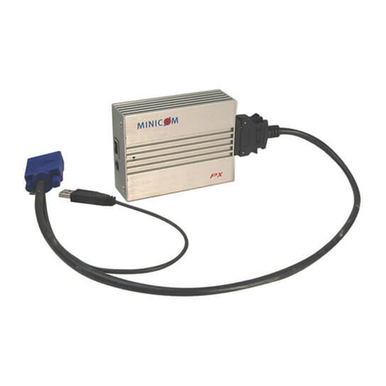
Connecting the PX
Where your network switch supports PoE (Power Over Ethernet),
power via the network cable. Alternatively they can receive power
power adapter.
To connect the PX:
1. Connect the 26 pin connector of the supplied USB-KVM cable
of the PX.
2. Connect the USB and Video connectors of the USB-KVM cable
ports of the Target server. See Figure 2 below. (For connection
computer, use the PS/2 cable p/n 5CB00611 - (ordered separate
the Keyboard, Video, and Mouse (KVM) connectors to the KVM
Target server.
3. Connect a network cable to the RJ45 port of the PX and to your
network switch.
4. Where relevant connect the power adapter to the PX power port.
PX
USB
CAT5 cable to PoE
network switch
Figure 2 PX connections
PX
QUICK GUIDE
Ethernet), PXs can receive
power from the optional
cable to the 26 pin port
cable to the relevant
connection to a PS/2 type
ately) and connect
KVM ports of the
our PoE enabled
port.
To Video port
Reset
button
Optional power
adapter
2
With the PX you can control, monitor
are, inside or outside the organization.
PX can be used as a standalone unit to
mouse) from any computer or server over
connection.
PX can also be used as part of a Central
KVM.net II) for access to servers and
using TCP/IP. Users login via the Central
connect to servers anywhere in the world.
Centralized Management s
For the Centralized Management system
components including the PX. The sheet
User Guide contains a list of all the de
extra sheets, photocopy them or print
CD.
The lists should include the following
•
A unique and clearly identifiable
•
The operating system
•
Non-default mouse settings. Default
Note! For Windows XP, 2003 Server
For Windows XP, 2003 Server and Vista
From the Control Panel select Printer
icon. The Mouse Properties box appea
tab.
Center the Motion section slider bar,
box. Click OK to save changes.
The PX has 2 green LEDs by the RJ45
PoE network switch and the other shows
particular PX is being accessed.
The PX comes with a versatile bracket
be connected to the PX and then mounted
•
Connect to the left or right side
•
Connect the PX to the bracket
•
Connect to different horizontal
To USB Port
Use the screws provided to connect the
of screws. Connect the 2 parts of the bra
headed screws. See Figure 4.
Connect section 2 of the bracket to the
screws. Note! The screws fit snugly into
indented.
PX
Intr
Introduction
and manage your server from wherever you
on.
to extend your KVM (keyboard, video, and
over TCP/IP via LAN, WAN or Internet
Centralized Management system (AccessIT or
network devices across geographic locations
Centralized Management Web interface to
world.
systems - Pre-installation guidelines
ems you need to prepare a list of all system
sheet supplied with the Centralized Management
details you need including the PX units. For
them from the softcopy files on the supplied
for each Target server:
iable name
Default mouse settings do not need to be listed
Server and Vista
ista deactivate Enhanced pointer precision.
ers and Other Hardware. Click the Mouse
appears. See Figure 1. Select the Pointer Options
Figure 1 Pointer tab
Figure
and uncheck the Enhanced pointer precision
1
PX
PX LEDs
RJ45 connector. 1 shows the PX is connected to
shows that the Target server connected to this
Connecting
nnecting the PX to a rack
acket in two sections see Figure 3. The bracket can
unted on a rack in many different ways.
side of the rack
bracket at different angles
ntal positions on the rack
Bracket section 1
Screw the brack
bracket sections
to the rear of
of the PX here
Figure 3 Rear of
of PX plus bracket sections
the bracket sections. There are 2 different types
brackets together with the 3 longer round
the rear of the PX with the 2 shorter flat headed
into the side of the bracket section 2 that is
3
Bracket section 2
Advertisement
Table of Contents

Related Manuals for Minicom 0SU70028


Summary of Contents for Minicom 0SU70028
-
Page 1: Quick Start Guide
Center the Motion section slider bar, and uncheck the Enhanced pointer precision www.tripplite.com/support box. Click OK to save changes. Copyright ©2012 Tripp Lite. All rights reserved. Copyright ©2012 Tripp Lite. All rights reserved. QUICK GUIDE Connecting the PX PX LEDs... - Page 2 QUICK GUIDE Assigning static IP addresses Where there is no DHCP server on the network, assign IP addresses as follows: Screw the bracket sections together with the 3 longer 1. Connect the PXs as described above, one at a time and open Internet Explorer. round headed screws 2.
Need help?
Do you have a question about the 0SU70028 and is the answer not in the manual?
Questions and answers