
Related Manuals for Minicom 0SU70017


Summary of Contents for Minicom 0SU70017
-
Page 1: User Guide
IP Control User Guide 1111 W. 35th Street, Chicago, IL 60609 USA www.tripplite.com/support Copyright ©2012 Tripp Lite. All rights reserved. -
Page 3: Legal Notice
Legal Notice Legal Notice This manual and the software described in it are furnished under license, and may be used or copied only in accordance with the terms of such license. The content of this manual is provided for informational use only, and is subject to change without notice. -
Page 4: About This Document
About this Document About this Document This document provides installation and operation instructions for the IP Control system, produced by Minicom Advanced Systems Limited. It is intended for system administrators and network managers. Chapters and Their Contents Introduction Provides an introduction to the document, IP Control Pg. -
Page 5: Style Conventions
About this Document Style Conventions Convention Used for Verdana Regular text. Arial Bold Names of menus, commands, buttons, and other elements of the user interface. Arial Italics Special terms, the first time they appear. Monospace Text entered by the user. Notes, which offer an additional explanation or a hint on how to overcome a common problem. -
Page 6: Table Of Contents
Table of Contents Table of Contents LEGAL NOTICE .....................I ABOUT THIS DOCUMENT ................II TABLE OF CONTENTS .................IV TABLE OF FIGURES .................. VII INTRODUCTION ..................9 ................9 RODUCT VERVIEW 1.1.1 Features and Benefits ..............9 ..................9 ERMINOLOGY .............10 LIENT OMPUTER PERATING YSTEM ..............10 ECHNICAL... -
Page 7: Table Of Contents
Table of Contents 3.5.3 Blocking a User..............26 3.5.4 Editing User Information ............26 KVM S .............27 ONFIGURING THE WITCH 3.6.1 Installing the Switch Definition File..........29 ..........29 ONFIGURING THE ERIAL ETTINGS 3.7.1 Assigning Serial Port .............30 .............30 ONFIGURING THE ECURITY ETTINGS ..........31 ONFIGURING THE YSTEM ATE AND... - Page 8 Table of Contents 4.10.2 Aligning the Mouse Pointers............53 4.10.3 Calibrating Mouse Pointers .............54 4.11 S ..........54 WITCHING TO A IFFERENT ERVER EVICE 4.12 D .............54 ISCONNECTING THE EMOTE ESSION TROUBLESHOOTING – SAFE MODE............55 .................55 NTERING ..............57 ESTORING ACTORY EFAULTS ............57 ESTORING THE EVICE...
-
Page 9: Table Of Figures
Table of Figures Table of Figures Figure 1 – IP Control Unit Front Panel ..............12 Figure 2 – IP Control Unit Back Panel ..............13 Figure 3 – IP Control Unit Connected to a Rack ............14 Figure 4 – IP Control Unit Connected to a Tabletop ........... 14 Figure 5 –... - Page 10 Table of Figures Figure 40 – Special Key Manager ................48 Figure 41 – Add a Predefined Key Dialog Box ............48 Figure 42 – Record Macro Box................49 Figure 43 – Delete Key(s) Confirmation Box............. 50 Figure 44 – Relative Mouse Settings ............... 51 Figure 45 –...
-
Page 11: Introduction
Introduction Product Overview 1 Introduction Congratulations on adding IP Control to your remote access tools. This document provides installation and operation instructions for Minicom’s IP Control. It is intended for system administrators and network managers, and assumes that readers have a general understanding of networks, hardware, and software. -
Page 12: Client Computer Operating System
Introduction Client Computer Operating System Term Definition The process of accessing and controlling target servers connected to IP Control from a user Remote session workstation 1.3 Client Computer Operating System The client computer operating system must be one of the following: ... - Page 13 Introduction WEEE Compliance Send old equipment for recycling on a one-for-one, like-for-like basis (this varies depending on the country) Send back the new equipment for recycling when it ultimately becomes waste Instructions for both customers and recyclers / treatment facilities wishing to obtain disassembly information are provided in our website www.minicom.com.
-
Page 14: Installation
Installation Overview 2 Installation 2.1 Overview Install the IP Control system as follows: 1. Remove the IP Control system from the package, and check that all components are present and in good working condition. 2. Mount the IP Control unit in a rack or under a tabletop. 3. -
Page 15: Mounting The Ip Control Unit
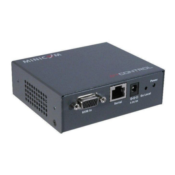
Installation Mounting the IP Control Unit Figure 2 – IP Control Unit Back Panel The following table describes the functionality of the elements of the IP Control back and front panels. Element Functionality For connecting the IP Control unit to the 10/100 Mbit Ethernet port on the Network switch LAN (Ethernet) via a cable. -
Page 16: Rack Mounting Safety Considerations
Installation Mounting the IP Control Unit Figure 3 – IP Control Unit Connected to a Rack Figure 4 – IP Control Unit Connected to a Tabletop Rack Mounting Safety Considerations 2.3.1 When mounting IP Control onto a rack, avoid the following conditions: ... -
Page 17: Connecting The System
Installation Connecting the System Connecting Figure Figure 5 – Holes for Rack/Tabletop Mounting To rack mount the IP Control unit: To rack mount the IP Control unit: 1. Connect the L-shaped brackets to the IP Control unit, using the screws provided. shaped brackets to the IP Control unit, using the screws provided. -
Page 18: Figure 7 - Ip Control Connections To A Computer
Installation Connecting the System It is recommended to place cables away from fluorescent lights, air conditioners, and machines that are likely to generate electrical noise. Figure 7 and Figure 8 illustrate the connections to a computer and KVM switch respectively, with the optional KVM console. Figure 7 –... -
Page 19: Figure 8 - Ip Control Connections To A Kvm Switch
Installation Connecting the System Figure 8 – IP Control Connections to a KVM Switch User Guide | 17... -
Page 20: Configuring The Network
Configuring the Network Boot-Up Process 3 Configuring the Network After the system has been installed and all connections have been made, you must configure the IP Control system as follows: 1. Configure IP Control’s network settings, which includes configuring: Device ID settings ... -
Page 21: Assigning Static Ip Addresses For A Number Of Units
Configuring the Network Logging Onto the Web Configuration Interface Figure 9 – Boot-Up Process Assigning Static IP Addresses for a Number of Units You can connect more than one IP Control to the same network. If there is no DHCP server, or you want to use static IP addresses, connect the IP Control units one at a time and change the static IP address of each unit before connecting the next unit. -
Page 22: Figure 10 - Web Page
Configuring the Network Logging Onto the Web Configuration Interface guration Interface Only one Administrator at a time can log Only one Administrator at a time can log onto the Web configuration interface. An idle nto the Web configuration interface. An idle timeout of 30 minutes terminates the session. -
Page 23: Web Configuration Interface Tabs
Configuring the Network Logging Onto the Web Configuration Interface Figure 12 – Network Configuration – Device Tab From the Configuration menu, you can configure the network, SNMP, Users, Switch Configuration, Serial Port, Security, and Date and Time settings. After making all configuration changes, you must click the button in the toolbar for the changes to go into effect. -
Page 24: Web Configuration Toolbar Buttons
Configuring the Network Configuring the Network Settings Web Configuration Toolbar Buttons 3.2.2 The following table describes the functionality of the Web configuration toolbar buttons. Button Functionality Saves the configuration changes Reloads the device settings into the configuration page parameter settings Reboots the device Upgrades the device firmware Restores the device with factory settings... -
Page 25: Configuring The Device Ip Address
Configuring the Network Configuring Configuring the Network Settings To configure Device ID settings evice ID settings: 1. In Device Name, type a name for IP Control type a name for IP Control. 2. In TCP Port, type the number of the port (from 800 to 65535) type the number of the port (from 800 to 65535). -
Page 26: Configuring Network Snmp Settings
Configuring the Network Configuring Network SNMP Settings In Manager IP Address, type the static IP address of the Centralized Management , type the static IP address of the Centralized Management , type the static IP address of the Centralized Management Manager. -
Page 27: Deleting User(S)
Configuring the Network Configuring User Settings Figure 14 – Users Page 2. Click the Add button. The Add User page appears. Figure 15 – Add User Page 3. Type a User Name and Password. The password must be at least six alphanumeric characters long and cannot include the user name, even if other characters are added. -
Page 28: Blocking A User
Configuring the Network Configuring User Settings You cannot delete an Administrator who is logged onto the system. You cannot delete an Administrator who is logged onto the system. You cannot delete an Administrator who is logged onto the system. To delete a User: 1. -
Page 29: Configuring The Kvm Switch
Configuring the Network Configuring Configuring Configuring the KVM Switch Figure 17 – Edit User Page 2. Change the Permission Permission and/or Access as required. 3. To change the password, click To change the password, click The Password parameter opens. In the upper textbox, type the new password; in parameter opens. -
Page 30: Figure 18 - Kvm Switch Configuration Page
Configuring the Network Configuring the KVM Switch Figure 18 – KVM Switch Configuration Page 2. From their respective dropdown lists, select the Manufacturer and Model of the connected KVM switch. If the KVM switch type used by the system does not correspond to any of those listed in the Manufacturer/Model dropdown lists, download the correct Switch Definition file, as described in Section 3.6.1. -
Page 31: Installing The Switch Definition File
Configuring the Network Configuring Configuring the Serial Port Settin the Serial Port Settings The server number The server number The server name, if the server is connected to the KVM switch; UNUSED if the The server name, if the server is connected to the KVM switch; UNUSED if the The server name, if the server is connected to the KVM switch;... -
Page 32: Assigning Serial Port
Configuring the Network Configuring the Security Settings Figure 20 – Serial Port Page 2. Type a Device Name and choose the correct device parameters. and choose the correct device parameters. 3. Select the Show checkbox to checkbox to display the Serial device in the list of servers/devices the Serial device in the list of servers/devices that can be accessed. -
Page 33: Configuring The System Date And Time
Configuring the Network Configuring Configuring the System Date and Time the System Date and Time Figure 21 – Security Page 2. In the Account Blocking Account Blocking section: In Block after, type e the number of allowable attempts to log in with a wrong in with a wrong username or password username or password in a time period specified in attempts within... -
Page 34: Performing Additional Configuration Operations
Configuring the Network Performing Additional Configuration Operations Additional Configuration Operations 2. In Date, type the current date: , type the current date: Day, Month, and Year. 3. In Time, type the current time: , type the current time: Hour, Minute, and Second. 3.10 Performing Additional Configuration Operations Performing Additional Configuration Operations Performing Additional Configuration Operations... -
Page 35: Upgrading Firmware
Configuring the Network Configuring Performing Additional Configuratio Additional Configuration Operations 6. Save the changes and restart the system, by clicking the Save the changes and restart the system, by clicking the button, and then button, button. button. Upgrading Firmware Upgrading Firmware 3.10.2 You can upgrade the IP Control firmware to take advantage of new features. -
Page 36: Restoring Factory Settings
Configuring the Network Reloading a Page The unit reboots. After about 30 seconds, the Login page appears. The unit reboots. After about 30 seconds, the Login page appears. Depending on the type of firmware upgrade, the following settings may Depending on the type of firmware upgrade, the following settings may Depending on the type of firmware upgrade, the following settings may be erased: User settings, KVM switch settings, mouse and video adjustments erased: User settings, KVM switch settings, mouse and video adjustments... -
Page 37: Saving Changes And Logging Out
Configuring the Network Configuring Saving Changes and Logging Out Changes and Logging Out The parameters are populated with the device settings. The parameters are populated with the device settings. 3.12 Saving Changes and Logging Out Saving Changes and Logging Out Once you have completed configuration changes, you must save them. -
Page 38: Figure 29 - Device Rebooting Progress Box
Configuring the Network Saving Changes and Logging Out Figure Figure 29 – Device Rebooting Progress Box Figure Figure 30 – Logon Page after Rebooting 3. Type your User name and name and Password and click Enter. The Configuration page opens. The Configuration page opens. -
Page 39: Conducting A Remote Session
Conducting Conducting a Remote Session Starting Starting a Remote Session 4 Conducting a Remote Session Conducting a Remote Session The remote session enables remotely accessing the server connected to IP Control. The remote session enables remotely accessing the server connected to IP Control. The remote session enables remotely accessing the server connected to IP Control. -
Page 40: Figure 31 - Logon Page
Conducting a Remote Session Starting a Remote Session Figure 31 – Logon Page Leave Mode as Remote Access. 4. In User and Password, type the default Administrator name and password, admin and access respectively (both lower case). 5. Click Enter. The screen of the target server or the currently selected server on the KVM switch that is connected directly to IP Control, appears with the IP Control toolbar. -
Page 41: Remote Session Toolbar Buttons
Conducting a Remote Session Sharing a Remote Session Remote Session Toolbar Buttons 4.1.1 The following table describes the functionality of the Remote Session toolbar buttons. Button Description Toggle button for displaying/hiding toolbar. Session button. Pressing this button opens up a dropdown menu for selecting: Session Profile –... -
Page 42: Exclusive Session
Conducting a Remote Session Displaying the Toolbar Figure Figure 33 – Shared Remote Session Exclusive Session Exclusive Session 4.2.1 When starting a remote session and there ar When starting a remote session and there are no other logged in users, a user can e no other logged in users, a user can prevent other users from connecting to the session (see Section prevent other users from connecting to the session (see Section 4.4, step 4). -
Page 43: Full Screen Mode
Conducting Conducting a Remote Session Setting Setting the Session Profile Figure Figure 34 – Session Profile Dialog Box 2. In Local Mouse Pointer Local Mouse Pointer, select one of the following options to set the appearance of the appearance of the client computer mouse pointer: mouse pointer: ... -
Page 44: Verifying Remote Presence Solutions Information
Conducting a Remote Session Verifying Remote Presence Solutions Information Remote Presence Solutions Information To exit full screen mode: 1. On the toolbar, click the Restore bu On the toolbar, click the Restore button The desktop window appears. The desktop window appears. Full screen mode can also be activated from the Session Profile box, see Full screen mode can also be activated from the Session Profile box, see Full screen mode can also be activated from the Session Profile box, see... -
Page 45: Figure 36 - Performance Settings
Conducting Conducting a Remote Session Changing the Video Performance Settings the Video Performance Settings Fixed – Enables you to select nables you to select any bandwidth option. For example, in a LAN bandwidth option. For example, in a LAN environment, it is best to set the bandwidth setting to environment, it is best to set the bandwidth setting to High. -
Page 46: Adjusting The Video
Conducting a Remote Session Adjusting the Video The chosen setting takes s effect and the screen of the last accessed target arget server appears. 4.7 Adjusting the Video Adjusting the Video There are three ways to adjust the video image: There are three ways to adjust the video image: ... -
Page 47: Manually Adjusting Video Settings
Conducting Conducting a Remote Session Adjusting the Video Manually Adjusting Video Settings Manually Adjusting Video Settings 4.7.3 Although automatic adjustment of video generally Although automatic adjustment of video generally optimizes the video view, you may optimizes the video view, you may want to fine-tune the results. -
Page 48: Power Managing The Target Servers
Conducting a Remote Session Power Managing the Target Servers 2. In Brightness and Contrast Contrast, use the scales to adjust the brightness and contrast of use the scales to adjust the brightness and contrast of the displayed image, respectively , respectively. Move the sliders to change the displayed image. . -
Page 49: Managing Keyboard Sequences
Conducting ucting a Remote Session Managing Keyboard Sequences Keyboard Sequences 4.9 Managing Keyboard Sequences Managing Keyboard Sequences You can select any keyboard sequence You can select any keyboard sequence (a combination of keys that performs a (a combination of keys that performs a specific process) that appears in the dropdown menu of the toolbar button that appears in the dropdown menu of the toolbar button that appears in the dropdown menu of the toolbar button... -
Page 50: Figure 40 - Special Key Manager
Conducting a Remote Session Managing Keyboard Sequences Figure 40 – Special Key Manager 2. Click the Add Predefined button. A list of existing sequences appears. Figure 41 – Add a Predefined Key Dialog Box 3. Select a key sequence and click OK. The sequence appears in the Special Key Manager box. -
Page 51: Recording A New Custom Key
Conducting Conducting a Remote Session Managing Keyboard Sequences Keyboard Sequences 4. In the Special Key Manager box, In the Special Key Manager box, click OK. The sequence appears in the Keyboard Key sequence list The sequence appears in the Keyboard Key sequence list. Recording a New Custom Key Recording a New Custom Key 4.9.2... -
Page 52: Deleting Key Sequence(S)
Conducting a Remote Session Synchronizing Mouse Pointers 3. On your keyboard, press the keys ress the keys to include in the key sequence. The names of the pressed keys he names of the pressed keys appear in the provided area. 4. -
Page 53: Manually Synchronizing The Mouse
Conducting Conducting a Remote Session Synchronizing Synchronizing Mouse Pointers Manually Synchronizing the Mouse Manually Synchronizing the Mouse 4.10.1 If the mouse settings on the If the mouse settings on the target server have been changed, or when the changed, or when the operating system on the target server target server is Windows XP / 2003 Server / 7 / 2008 Server, Linux, 2008 Server, Linux,... -
Page 54: The Usb Option
Conducting a Remote Session Synchronizing Mouse Pointers Examples The following are examples of the instructions for two different target operating systems. After performing the instructions for the selected operating system, you should click OK to synchronize the mouse pointers. 1. For Windows 7 Go to the Mouse Properties on the target and clear the Enhance pointer precision checkbox. -
Page 55: Advanced Mouse Emulation
Conducting Conducting a Remote Session Synchronizing Synchronizing Mouse Pointers Phantom Specter USB, or , or unsupported operating systems or SUN Solaris ris), use the USB option. Advanced Mouse Emulation Advanced Mouse Emulation In the Advanced Mouse settings, you can set the type of mouse that you would like IP In the Advanced Mouse settings, you can set the type of mouse that you would like IP In the Advanced Mouse settings, you can set the type of mouse that you would like IP Control to emulate. -
Page 56: Calibrating Mouse Pointers
Conducting a Remote Session Switching to a Different Server/Device To align the mouse pointers To align the mouse pointers: 1. On the toolbar, select > Align (or press Ctrl+M The mouse pointers align. Calibrating Mouse Po Calibrating Mouse Pointers 4.10.3 A target server may have a different mouse pointer speed than the may have a different mouse pointer speed than the client computer client computer. -
Page 57: Troubleshooting - Safe Mode
Troubleshooting – Safe Mode Entering Safe Mode 5 Troubleshooting – Safe Mode From Safe mode, you can: – When you cannot access the system (for example, you Restore factory defaults have forgotten the Username or Password), you can restore factory defaults from Safe mode (see Section 3.10.3 on page 34 on how to restore factory settings from the Web interface). -
Page 58: Figure 48 - Login Page
Troubleshooting – Safe Mode Restoring Factory Defaults To enter Safe mode: 1. While powering up IP Control, press and hold down the While powering up IP Control, press and hold down the Go Local button on the button on the back panel of the unit for for three to four seconds. -
Page 59: Restoring Factory Defaults
Troubleshooting Troubleshooting – Safe Mode Restoring Factory Defaults Restoring 5.2 Restoring Factory Defaults Restoring Factory Defaults You can restore all IP Control settings to their default values. You can restore all IP Control settings to their default values. To restore factory defaults To restore factory defaults: 1. -
Page 60: Figure 53 - Update Succeeded
Troubleshooting – Safe Mode Restoring the Device Firmware The firmware upgrades. When the process finishes, the following figure appears. Figure 53 – Update Succeeded 3. Click Reboot to restart the unit. 58 | IP Control... -
Page 61: Technical Specifications
Technical Specifications 6 Technical Specifications Specification Description Target server – DOS, Windows, Novell, Linux, or SUN Solaris for PC Operating systems Client computer – Windows 2000 or later with Internet Explorer 7.0 / Firefox 3.0 and later; Linux x86 with Firefox 3.0 and later Target server –... -
Page 62: Video Resolution And Refresh Rates
Video Resolution and Refresh Rates 7 Video Resolution and Refresh Rates Hz → 640x480 720x400 800x600 1024x768 1152x864 1152x900 1280x720 1280x768 1280x960 1280x1024 1600x1200 60 | IP Control... - Page 63 201204188 • 933203_EN...
Need help?
Do you have a question about the 0SU70017 and is the answer not in the manual?
Questions and answers