Advertisement
Model No. WECCSY57740
Serial No.
Write the serial number in the
space above for future reference.
Serial Number Decal (under seat)
QUESTIONS?
As a manufacturer, we are com-
mitted to providing complete
customer satisfaction. If you
have questions, or if there are
missing parts, please call:
1-888-936-4266
Mon.–Fri. 8h00 until 18h30 EST
(excluding holidays).
CAUTION
Read all precautions and instruc-
tions in this manual before
using this equipment. Save this
manual for future reference.
USER'S MANUAL
w
Visit our website at
www.weiderfitness.com
Advertisement
Table of Contents

Related Manuals for Weider Cross Bow By 1500x


Summary of Contents for Weider Cross Bow By 1500x
- Page 1 Model No. WECCSY57740 Serial No. Write the serial number in the space above for future reference. Serial Number Decal (under seat) QUESTIONS? USER’S MANUAL As a manufacturer, we are com- mitted to providing complete customer satisfaction. If you have questions, or if there are missing parts, please call: 1-888-936-4266 Mon.–Fri.
-
Page 2: Table Of Contents
1-888-936-4266 to order a free replace- ment decal. Apply the decal in the loca- tion shown. Keep hands and fingers clear of this area. ATTENTION Gardez vos mains et vos doigts éloignés de cet endroit. MAX by WEIDER is a trademark of ICON IP, Inc. -
Page 3: Important Precautions
Use the resist- used with the included resistance, and the ance system only as described in this manual. resistance included with a MAX by WEIDER ™ Power Pak. Do not use the resistance system 2. It is the responsibility of the owner to ensure with any other type of resistance. -
Page 4: Before You Begin
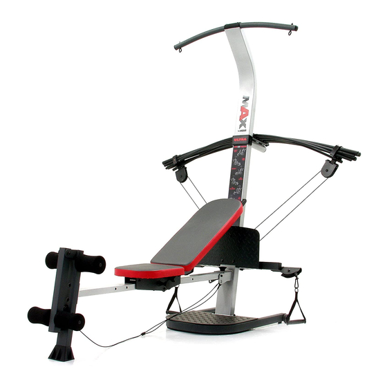
BEFORE YOU BEGIN Thank you for selecting the innovative MAX by WEI- questions, please call our toll-free customer service department at 1-888-936-4266, Monday through Friday ™ 1500X resistance system. The resistance system offers a selection of stations designed to develop every 8h00 until 18h30 eastern time (excluding holidays. -
Page 5: Assembly
ASSEMBLY • Tighten all parts as you assemble them, unless Make Things Easier for Yourself instructed to do otherwise. This manual is designed to ensure that the resist- • As you assemble the resistance system, make ance system can be assembled successfully by sure all parts are oriented as shown in the draw- most people. - Page 6 2. Attach a Wheel (31) to the outside of the Base (1) with an M10 x 108mm Bolt (81), three M10 Washers (75), and an M10 Nylon Locknut (76). Do not overtighten the Nylon Locknut; the Wheel must be able to turn easily. Attach the other Wheel (not shown) in the same manner.
- Page 7 6. Pull the Seat Knob (45, not shown) out as far as Third it will go, and slide the Seat Carriage (12) onto Hole the Bench Rail (5). Engage the Seat Knob into the third hole from the end of the Bench Rail. See the inset drawing.
- Page 8 9. Press two 38mm Round Inner Caps (38) into the ends of the Top Frame (10). Attach two Eyebolts (34) to the Top Frame (10) with two M8 Washers (59) and two M8 Nylon Locknuts (65). Do not overtighten the Locknuts; the Eyebolts must be able to rotate freely.
- Page 9 12. Locate the Resistance Bar Fulcrum (18) on the Lat Tower (4) (see the inset drawing). Slide the Tray (35) onto the rods on the Resistance Bar Fulcrum. Make sure the Spacer is oriented as shown in the drawing. Back Set the Resistance Bars into the Tray (35) in the following order: the 10-pound Removable Resistance Bar (67), the 20-pound Removable...
- Page 10 15. Press two 50mm Round Inner Caps (57) into the top and bottom of the Leg Developer (19). Press two 45mm Round Inner Caps (56) into the top Tube and bottom of the Leg Lever (7). Lubricate an M10 x 69mm Bolt (60) with grease. Attach the Leg Lever (7) to the Leg Developer (19) with the Bolt and an M10 Nylon Locknut (76).
- Page 11 19. Attach a Pulley Housing (94) to the indicated “U”- channel on the 10-pound Center Resistance Bar (44) with an M10 x 102mm Button Head Bolt (24), two Pivot Bushings (74), and an M10 Nylon Locknut (76). “U”-Channel Wrap the Long Cable (80) around a 90mm Pulley (28).
- Page 12 23. Make sure there are no Resistance Bars (not shown) under the “U”-channels on the 10-pound Center Resistance Bar (not shown). Have a sec- ond person pull on the Long Cable (80) to create slack in the Cable. Insert the end of the Long Cable (80) through the welded tube on the indicated end of the Cross Tube (11) and then through the remaining Swivel Arm (22).
-
Page 13: Adjustments
ADJUSTMENTS This section explains how to adjust the resistance system. See the EXERCISE GUIDELINES on page 17 for important information about how to get the most benefit from your exercise program. Also, refer to the accompa- nying exercise guide to see the correct form for each exercise. Make sure all parts are properly tightened each time you use the resistance system. - Page 14 ATTACHING THE ACCESSORIES To attach a Short Handle (49) to a high pulley, first attach the high pulley to the resistance system (see ATTACHING THE HIGH PULLEYS AND LEG LEVER on page 13). Then, attach the Short Handle to the Short Cable (33) with a Cable Clip (51).
-
Page 15: Adjusting The Backrest
ADJUSTING THE BACKREST The Backrest (14) can be used in a level position or one of three inclined positions. To use the Backrest in a level position, secure the Seat Carriage (12) at the hole Slot in the Bench Rail (5) closest to the Leg Developer (19) (see ADJUSTING THE SEAT on page 13). -
Page 16: Cable Diagram
USING THE REMOVABLE RESISTANCE BARS The Removable Resistance Bars (36, 67) can be used to exercise apart from the resistance system, as shown in the video or on the exercise guide. To remove a Resistance Bar, pull it out of the Tray (35). To replace the Removable Resistance Bars (36, 67), slide them into the Tray (35) from the side shown, so that the arrows on the rings point toward the Tray. -
Page 17: Exercise Guidelines
EXERCISE GUIDELINES THE FOUR BASIC TYPES OF WORKOUTS PERSONALIZING YOUR EXERCISE PROGRAM Muscle Building Determining the exact length of time for each workout, To increase the size and strength of your muscles, as well as the number of repetitions or sets completed, push them close to their maximum capacity. -
Page 18: Muscle Chart
Rest for a short period of time after each set. The slowly as you stretch and do not bounce. Ease into ideal resting periods are: each stretch gradually and go only as far as you can • Rest for three minutes after each set for a muscle without strain. - Page 19 EXERCISE RESISTANCE SETS REPS MONDAY Date: AEROBIC EXERCISE TUESDAY Date: EXERCISE RESISTANCE SETS REPS WEDNESDAY Date: THURSDAY AEROBIC EXERCISE Date: EXERCISE RESISTANCE SETS REPS FRIDAY Date: Make photocopies of this page for scheduling and recording your workouts.
-
Page 20: Ordering Replacement Parts
(excluding holidays). When ordering parts, please be prepared to give the following information: • The MODEL NUMBER of the product (WECCSY57740) • The NAME of the product (MAX by WEIDER 1500X resistance system) • The SERIAL NUMBER of the product (see the front cover of this manual) •... - Page 21 PART IDENTIFICATION CHART Refer to the drawings below to identify small parts used in assembly. The number in parentheses below each drawing is the key number of the part, from the PART LIST on the reverse side of this page. Important: Some parts may have been pre-assembled for shipping purposes.
- Page 22 PART LIST—Model No. WECCSY57740 R0105A Key No. Qty. Description Key No. Qty. Description Base M10 x 69mm Bolt Base Plate Seat Wheel Upright M4 x 16mm Screw Lat Tower M6 Zinc Nylon Locknut Bench Rail M10 x 72mm Bolt Front Leg M8 Nylon Locknut Leg Lever M10 x 132mm Bolt...
- Page 23 EXPLODED DRAWING—Model No. WECCSY57740 R0105A 58 62 89 62...
Need help?
Do you have a question about the Cross Bow By 1500x and is the answer not in the manual?
Questions and answers