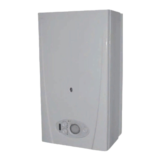
To b e l e f t w i t h t h e u s e r F24e G.C. No. 47-920-45 HIGH EFFICIENCY CONDENSING COMBINATION BOILER F28e G.C. No. 47-920-39 HIGH EFFICIENCY CONDENSING COMBINATION BOILER F28e SB G.C. No. 41-920-37 HIGH EFFICIENCY CONDENSING SYSTEM BOILER Saunier Duval, Nottingham Road, Belper, Derbyshire. DE56 1JT www.saunier-duval.co.uk...
Guarantee Registration Thank you for installing a new Saunier Duval appliance in your home. Saunier Duval appliances' are manufactured to the very highest standard so we are pleased to offer our customers' a Comprehensive Guarantee. This product is guaranteed for 24 months from the date of installation or 30 months from the date of manufacture, whichever is the shorter, for parts.
Contents The instructions consist of three parts, User, Installation and Servicing Instructions, which includes the Guarantee Registration Card. The instructions are an integral part of the appliance and must, to comply with the current issue of the Gas Safety (Installation and Use) Regulations, be handed to the user on completion of the installation.
Saunier Duval. going to the lavatory. Any alteration not approved by Saunier Duval, could invalidate If you do suffer irritation to the eyes or severe irritation to the skin the certification, boiler warranty and may also infringe the seek medical attention.
Introduction - Manual Handling IMPORTANT. With regards to the Manual Handling Operations, Carriage of carton from point of delivery to 1992 Regulations, the following lift operations are recommended point of installation - roofspace. as the appliance weight exceeds a one man lift. Recommend 2-person lift.
Introduction - Manual Handling Positioning of Appliance for Final Installation - above worktop, foreseeable obstructions etc. Recommend 2 persons lift appliance to position into place. Fit bracket securely onto wall before lifting appliance into position. Obtain firm grip on front and sides of appliance, lift upwards, onto worktop if practicable.
User Instructions - Appliance Introduction The EnviroPlus F24e & F28e boilers are wall mounted high Accessories efficiency condensing combination boilers with electronic ignition A range of accessories are available. providing central heating and instantaneous hot water. For further information contact your supplier.
Saunier Duval. Do not use abrasive or solvent cleaners. If a part is required contact Saunier Duval Service using the telephone number on the inside front cover of this booklet. Maintenance and Servicing Please quote the name of the appliance, this infomation will be on the name badge on the front of the appliance.
Check that all isolating valves on the boiler are open and that water flows from the hot water tap. If you are in any doubt about the boiler being filled with water contact your installer or Saunier Duval's own service organisation using the telephone number on the inside front cover of this booklet.
Page 10
(b) and then tap (a). If the system repeatedly loses pressure, YOU MUST CONTACT YOUR INSTALLER OR SAUNIER DUVAL'S OWN SERVICE ORGANISATION USING THE TELEPHONE NUMBER ON THE INSIDE FRONT COVER OF THIS BOOKLET.
Page 11
User Instructions - (F24e & F28e ONLY) Optional Programmer General description The programmer is factory preset which switches the boiler on and off up to three times a day as shown below. FACTORY PRESET TIMES 6.30 8.30 2nd ON 12.00 2nd OFF 12.00 16.30...
Page 12
User Instructions - (F24e & F28e ONLY) Optional Programmer To set the programmer ON and OFF times Note: The programmer can be set to give a minimum of one and a maximum of three "ON" and "OFF" times. Place the slide switch to "SET". Press the "enter"...
1 Technical Data Net lift weight (boiler only) (F24e 47 kg) (F28e 47 kg) (F28e SB 42 kg) Gross lift weight (boiler and packaging) (F24e 52 kg) (F28e 52 kg) (F28e SB 47 kg) Diagram 1.1 The boiler and fittings pack are delivered in one carton. The flue is supplied separately.
Page 14
1 Technical Data (F24e ONLY) Heating (F24e ONLY) Hot water Heat input (max) NET Q 25.6 kW Heat input (max) NET Q 25.6 kW 87,347 BTU/H 87,347 BTU/H Heat input (min) NET Q 5.0 kW Heat input (min) NET Q 5.0 kW 17,060 BTU/H 17,060 BTU/H...
Where no specific instructions are given, reference should be permission, in writing, from Saunier Duval. made to the relevant British Standard Code of Practice. Any alteration that is not approved by Saunier Duval, could invalidate the warranty and could also infringe the current issue of the Statutory Requirements.
Page 16
3 Heating System Design - The EnviroPlus F24e, F28e and F28e SB are for use with 3.2 Filling the Sealed System sealed central heating systems. NOTE: The water pressure at the boiler must be at least 1.2bar - The safety valves are an integral part of the boiler and cannot to enable filling the boiler to a minimum pressure.
3 Heating System Design Additional Boiler expansion vessel (if required) Bypass (if required) Control valve Drain point Heating circuit Diagram 3.2a TYPE CA FILLING LOOP TAP (b) EXTENSION TAP (a) EXTENSION Diagram 3.4 (F24e & F28e ONLY) Diagram 3.3 4 (F24e & F28e ONLY) Domestic Hot Water System Design - The boiler will operate with a supply pressure of 0,6 bar, but All domestic hot water circuits, connections, fittings must be in under reduced flow rate.
6 Boiler Location, Flue and Ventilation 6.1 Location This boiler is not suitable for outdoor installation. This boiler may be installed in any room, although particular attention is drawn to the installation of a boiler in a room containing a bath or shower where reference must be made to the relevant requirements.
Page 21
Institute of Gas Engineers document IGE/UP/7/1998. If in doubt seek advice from the local gas undertaking or Saunier Duval. 6.6 Room Ventilation The boiler is room sealed, so when it is installed in a room or space, a permanent air vent is not required.
7 Installation Preparation and Appliance Fixing 7.1 Unpacking of Boiler When using extension pipes with the horizontal rear flue, a core drill size of 125mm should be used to allow the extension pieces IMPORTANT: With regards to the Manual Handling Operations, to slope at 35mm/metre (2.5 ) towards the boiler.
8 Horizontal Top Flue Preparation and Fitting The standard horizontal flue is fitted onto the top of the boiler WALL THICKNESS 'X' = 75 TO 527mm using the flue adaptor. See diagrams 8.1 to 8.3 to determine whether a standard flue can be used.
Page 24
8 Horizontal Top Flue Preparation and Fitting 8.2 Rear Flue (LIPS POINT INWARDS) FLUE ELBOW Mark the air duct assembly and the flue duct at the lengths shown in diagram 8.4. Then cut to length, cutting square and removing any burrs. 8.3 Standard Side Flue Fit the flue spigot 'H', supplied with the boiler with the three securing screws to the top of the boiler.
Page 25
8 Horizontal Top Flue Preparation and Fitting 8.5 Flue Assembly 8.6 Flue Attachment to Boiler, refer to Diagram 8.6. The flue assembly is an entirely push fit design. The lip seals should be fitted in the correct orientation into the Internal rear flue fitting.
8 Twin Flue Preparation and Fitting TWIN FLUE 1M EXTENSION ADAPTOR KIT Pt.No.08547800 (Aluminium) Pt.No.A2025000 PITCHED ROOF TWIN PIPE TO WEATHER COLLAR CONCENTRIC Pt.No.08510500 ADAPTOR 0.5M EXTENSION Pt.No.08511800 Pt.No.08547600 (Aluminium) FLAT ROOF 0.5M EXTENSION AIR DUCT WEATHER COLLAR Pt.No.08547200 (Plastic) Pt.No.08510700 SINGLE PIPE TO TERMINAL...
Page 29
8 Twin Flue Preparation and Fitting FLUE CONFIGURATION EXAMPLE INCLUDING DIMENSIONS TO AID CUTTING AND INSTALLATION AIR DUCT 45°ELBOW TERMINAL 1000 1 METRE EXTENSION 1 METRE EXTENSION 1 METRE FLUE DUCT 90°ELBOW EXTENSION TERMINAL TWIN FLUE ADAPTOR Diagram 8.11 An Example Twin Flue Installation. (The flue assembly is an entirely push fit design), see diagram 8.11.
Page 30
8 Twin Flue Preparation and Fitting 90°ELBOW SEALING COLLARS 1 METRE EXTENSION (cut to fit) 90°ELBOW AIR DUCT TERMINAL SEALING COLLARS FLUE DUCT TERMINAL Diagram 8.13 1 METRE EXTENSION CONCENTRIC EXTERNAL INTERNAL HORIZONTAL CONCENTRIC SEALING SEALING TERMINAL ADAPTOR COLLAR COLLAR Diagram 8.14 2000225294A...
Page 31
8 Twin Flue Preparation and Fitting FLAT ROOF FLASHING VERTICAL ROOF TERMINAL VERTICAL ROOF TERMINAL After installation the vertical roof terminal must be secured with a Fit flat roof or pitched fixing bracket weather collar onto SINGLE CONCENTRIC vertical roof terminal. PIPE ADAPTOR Make sure a weather...
9 Gas/Water Connections These packs are for the (F24e & F28e ONLY) Packs supplied with the boiler 4. Pipe pack containing 1. Isolating valve pack containing Central heating pipe (2 off) Heating isolating valves (2 off) Domestic water pipe (2 off) Domestic cold water isolating valves (1 off) Gas pipe (1 off) Domestic hot water elbow (1 off)
Page 33
9 Gas/Water Connections ISOLATING VALVE ON/OFF LEVER ISOLATING VALVE (F24E & F28e ONLY) DOMESTIC COLD WATER CENTRAL ISOLATING INLET ISOLATING ALL VALVES SHOWN IN HEATING VALVE FLOW AND VALVE CLOSED POSITION RETURN ISOLATING (F24E & F28e ONLY) (F24E & F28e ONLY) VALVES TAP EXTENSION DOMESTIC...
Page 34
9 Gas/Water Connections These packs are for the (F28e SB ONLY) Packs supplied with the boiler 4. Pipe pack containing Central heating pipe (2 off) 1. Isolating valve pack containing Domestic water pipe (2 off) (F28e ONLY) Heating isolating valves (2 off) Gas pipe (1 off) Gas isolating valve (1 off) 1/2 in.
10 Safety Discharge Valve and Condensate Connections 10.1 Safety Discharge Valve SAFETY DISCHARGE A short discharge pipe with nut and washer are supplied in a VALVE pack at the bottom of the boiler packaging. Connect the discharge tube to the heating safety valve. This must be extended, using not less than 15mm o.d.
Page 36
10 Safety Discharge Valve and Condensate Connections INTERNAL SOIL EXTERNAL SOIL AND VENT STACK AND VENT STACK BOILER BOILER EXTERNAL MAX. 3M MIN. DIA. 21MM MIN. DIA. 21MM NO RESTRICTION NO RESTRICTION ON LENGTH ON LENGTH Internal Soil and Vent Pipe External Soil and Vent Pipe or Rainwater Pipe BOILER SINK...
(E), fitted between the two terminals of the heating of the Saunier Duval guarantee. controls connection, is left in place, see diagram 11.1. All system components must be of an approved type.
Page 38
11 Electrical Connections Route the external controls cable through to the rear of the control panel where the other cables exit. External controls should be fitted in accordance with the rules in force. Refer to Section 15 wiring diagram. 11.3 Electrical Connections - Testing Carry out preliminary electrical system checks as below: 1.
12 Commissioning Please ensure the "Benchmark" logbook is completed and left with the user. Undo cap on automatic air vent on top of boiler The commissioning and first firing of the boiler must only be done by a competent person. and leave undone.
Page 40
12 Commissioning 12.3 Initial Lighting 12.5 Instruct the User - Adjust heating temperature to maximum, refer to User Controls Instruct and demonstrate the lighting procedure and advise the and Lighting. user on the safe and efficient operation of the boiler. - Check that any system controls, if fitted, are calling for heat Instruct on and demonstrate the operation of any heating (set room thermostat to maximum).
13 Servicing 13.1 General RETAINING Measurement of the products of combustion can be achieved by connection of a probe to the flue elbow or alternatively to the LUGS sample point at the base of the flue outlet pipe inside the boiler, see diagram 13.2.
Page 42
13 Servicing 13.3 Burner and Fan SECURING PLATE SCREW Refer to diagram 13.4. HEATING FLOW (Slacken pull ELECTRICAL Remove spark electrode lead, heating flow thermistor electrical forwards CONNECTIONS connections and electrical connections to the fan and gas valve. to remove) Remove gas pipe securing clip.
13 Servicing 13.5 Condensate Drain FIXING Refer to diagram 13.5 and 13.6. BRACKET Remove condensate drain pipe. Slide fixing bracket forward and remove, ease condensate CONDENSATE drain down off the inlet connection. DRAIN Carefully remove the condense drain taking care not to spill any water which may be in the unit.
Page 44
13 Servicing Adjustment of the CO at minimum rate is very coarse so OFFSET carefully adjust the CO with the offset adjustment to 8.3%, see ADJUSTMENT diagram 13.9. Rotate the service potentiometer fully clockwise, see diagram 13.8 and recheck the maximum rate combustion, which should be 9.3% ±...
Page 45
13 Servicing 13.9 Draining of Boiler Heating Circuit Drain down the Heating Circuit of the boiler only, by closing the heating flow and return isolating valves, see diagram 9.2. Refer to diagram 13.12. Attach a length of hose to the drain point and open the drain valve.
14 Fault Finding When trying to operate the boiler make sure that : WARNING: Always isolate the boiler from the electrical supply before carrying out any electrical replacement work. - All gas supply cocks are open and that the gas supply has been purged of air.
Page 47
14 Fault Finding To carry out the electrical test, gain access to the Control Box PCB, as follows: Hinge down the control box. Remove Torx screws and unhook the rear panel. For layout of PCB, see (F24e / F28e) diagram 15.1 or (F28e SB) diagram 15.1a To check components see (F24e / F28e) Table 1 or (F28e SB) Table 1a .
Page 48
14 Fault Finding (F24e / F28e ONLY) Table 1. (F28e SB ONLY) Table 1a. COMPONENT C.H. thermistor 10K Ω @ 25°C 24V DC accross terminals on fan, 40V dc in standby mode, see diagram 14.2. Check 3.15 AT fuse on DC fan supply. Gas Valve 24VDC/55 Ω...
15 Wiring Diagram MAINS VOLTAGE HEATING CONTROLS PLUG REMOVE VOLTAGE FREE LINK 230V SWITCHED LIVE FROM OPTIONAL FROST STAT. 230V SWITCHED LIVE FROM HEATING CONTROLS. VOLTAGE FREE HEATING CONTROLS PLUG LINK REMOVE THE LINK IF FITTING VOLTAGE FREE OR 230V SYSTEM CONTROLS.
16 Replacement of Parts 16.1 General 16.5 Transformer For access, refer to section 16.1. Replacement of parts must be carried out by a competent person. Refer to diagram 16.2. Before replacing any parts the boiler should be isolated from the Unplug electrical connection from the transformer.
Page 53
16 Replacement of Parts 16.6 Gas Control Valve For access, refer to section 16.1. Refer to section 13.3 for removal of the fan/gas control valve SECURING and silencer assembly. SCREW (3) Remove the gas control valve and plate which is held by the three plate securing screws, see diagram 16.4.
Page 54
16 Replacement of Parts 16.10 Pump (head only) 16.9 (F24e/F28e ONLY) Plate to Plate Heat Exchanger For access, refer to section 16.1. Drain the heating circuit, see section 13.9. Drain the boiler heating circuit, see section 13.9. Drain the hot water circuit, see section 13.10. Make sure that the filling loop valves are closed, then proceed as Section 16.19 (F24e or F28e only).
Page 55
16 Replacement of Parts 16.11 Expansion Vessel (F24e/F28e ONLY) 16.11a Expansion Vessel (F28e SB ONLY) For access and to hinge Rhd. side panel, refer to section 16.1. For access and to hinge R/H side panel, refer to section 16.1. Drain the boiler heating circuit, see section 13.9. Drain the boiler heating circuit, see section 13.9.
Page 56
16 Replacement of Parts 16.12 Safety Discharge Valve SAFETY SECURING DISCHARGE For access, refer to section 16.1. CLIP VALVE Drain down the heating circuit, see section 13.9. Refer to section 13.9 and drain the boiler heating circuit. Refer to diagram 16.9 Undo the safety discharge valve coupling and remove from the pipework.
Page 57
16 Replacement of Parts 16.15 (F24e/F28e ONLY) Central Heating Return Thermistor For access, refer to section 16.1. Refer to diagram 16.12. Remove the electrical connections from the thermistor. Remove the thermistor and retaining clip from the flow pipe. Fit the replacement thermistor using the heat sink compound supplied.
Page 58
16 Replacement of Parts 16.18 (F24e/F28e ONLY) Flow Sensor AIR VENT For access, refer to section 16.1. Refer to section 13.10 and drain the boiler hot water circuit. Refer to diagram 16.15. Remove the electrical connection to the flow sensor. Remove the securing clip between the flow sensor and the plate to plate heat exchanger.
Page 59
16 Replacement of Parts 16.21 (F24e/F28e ONLY) Three Way Valve ELECTRICAL Refer to sections 13.9 and 13.10. CONNECTIONS Remove the Reduced Pressure Zone Valve Refer to Section 16.19. Remove the electrical connection from the three way valve, see diagram 16.7. Remove the pipe assembly from between the cold water inlet isolation valve to cold water filter housing, see diagram 13.10.
Page 60
16 Replacement of Parts 16.25 Condense Drain RETAINING For access, refer to section 16.1. LATCHES Refer to section 13.5. 16.26 Access to Switches, User Interface and Programmer For access, refer to section 16.1. Release the front of the fascia by carefully unclipping the two retaining latches, see diagram 16.19.
Page 61
16 Replacement of Parts 16.32 Control Box THREE WAY For access, refer to section 16.1. VALVE PCB SECURING (F24e/F28e ONLY) SCREWS (2) Remove relevant plugs and connectors, refer to wiring diagrams section 15. Withdraw grommets and leads so they are hanging loose. Unthread the retaining cord and remove the control box by drawing it outwards away from its retaining slots, see relevant part of diagram 11.1.
Page 62
16 Replacement of Parts 16.35 Heat Exchanger Refer to section 16.1. Drain the boiler heating circuit, see section 13.9. Drain the boiler hot water circuit, see section 13.10. Remove the flue elbow, water and gas connections at the bottom of the boiler, any electrical connections. Lift the boiler up and off the hanging bracket, carefully lay the boiler on its back on the floor.
17 Spare Parts When ordering spare parts, contact Saunier Duval service organisation using the telephone number on the inside front cover of this booklet. Please quote the name of the appliance and serial number, to be found on the data label.
Page 64
17 Spare Parts Diagram 17.1 Because of our constant endeavour for improvement, details may vary slightly from those shown in these instructions. 2000225294A...
Need help?
Do you have a question about the EnviroPlus F24e and is the answer not in the manual?
Questions and answers