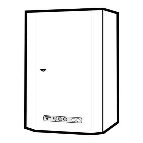
Summary of Contents for Saunier Duval Sylva FF 24 E
-
Page 1: Servicing Instructions
SYLVA Servicing instructions I N W A R R A N T Y T E C H N I C A L H E L P L I N E 01773 828400 01773 828100 THIS IS A CAT II2H3+ APPLIANCE... -
Page 3: Table Of Contents
SERVICING INSTRUCTIONS SYLVA Note! The boiler serial number is marked on the label attached to the inside of the door. Refer to the «Introduction» section page 3 of the Installation and User instructions for a description of the basic functions of the boiler. The «Users» section describes how to safely operate the boiler. CONTENTS Routine cleaning and inspection ........ -
Page 4: Routine Cleaning And Inspection
ROUTINE CLEANING AND INSPECTION To ensure the continued efficient and safe opera- Diagram. 1 tion of the boiler it is recommended that it is checked and serviced at regular intervals. The frequency of servicing will depend upon the particular installa- tion conditions and usage, but in general once a year should be enough. - Page 5 ROUTINE CLEANING AND INSPECTION Flue system Check externally to make sure that flue is not blocked Inspect flue system to make sure that all fittings are secure. Operation of fan Switch on electrical supply and turn on gas. Set selector switch to ‘Winter’ position.
-
Page 6: Replacement Of Parts
REPLACEMENT OF PARTS For replacement of the following components it will Close isolating valves on flow and return pipes on be necessary to remove boiler casing panels as des- boiler, see diagram 3. cribed in ‘Routine Cleaning and Inspection’. Note: 1) These valves are closed when levers are at right angles to direction of flow. - Page 7 REPLACEMENT OF PARTS Undo and remove screw securing electrical cover Note: It is not necessary to drain down entire heating onto pump housing and remove cover. system to carry out this work. Disconnect electrical connections from pump. Remove 3-way valve head as described previously. Connect electrical connections to replacement Unscrew three nuts securing 3 - way valve to pump and refit cover.
- Page 8 REPLACEMENT OF PARTS Withdraw gas valve assembly. Isolate electrical supply to boiler. Using old gas valve as a guide, transfer gas pipes Close isolating valve (c) on cold water inlet pipe, from old gas valve to replacement gas valve. see diagram 3. Fit replacement gas valve into boiler.
- Page 9 REPLACEMENT OF PARTS Diagram. 9 To replace central heating expansion vessel Drain down heating circuit of boiler only as described in 'To replace pump'. Note: It is not necessary to drain down entire heating system to carry out this work. Isolate electrical supply to boiler.
-
Page 10: Fan
BOILER SCHEMATIC SYLVA FF 24 E 1 - 3-way valve 17 - Expansion valve (6 bar) 2 - Loss of water switch 18 - Domestic expansion vessel 3 - Pump 19 - Drain valve 4 - CVI unit 20 - Fan... -
Page 11: Burner
TECHNICAL DATA Heating output Hot water output adjustable from 10,8 kW to 24 kW automatically variable from 10,8 kW to 24 kW 36,850 BTU/H to 81,890 BTU/H 36,850 BTU/H to 81,890 BTU/H Efficiency 81 % Storage capacity 60 l 90 °C 65 °C Maximum heating temperature Maximum hot water temperature... -
Page 12: Schematic Wiring Diagram
SCHEMATIC WIRING DIAGRAM ACF ........Flame control circuit K4 ........Overheat thermostat A1 ........230V Connector K5 ........Loss of water switch A3-A5 ........ 24V Connectors LK4 ........Safety reset light A7 ........Clock option connector L.alim ......... Mains supply light BR ........ -
Page 13: Fault Finding
FAULT FINDING Before trying to operate the boiler make sure that : For example: All gas supply cocks are open and that the gas If the domestic hot water works but the heating supply has been purged of air. doesn’t, refer to chart No. 1. The heating system pressure is at least 1 bar. - Page 14 FAULT FINDING ° CHART N Does burner fire? Is burner pressure correct? - Refer to technical data. NO CENTRAL HEATING Does burner fire when a hot tap Heating ok. is opened for approximately 3 minutes ? Is the range rating potentiometer correctly adjusted? Refer to chart No.3.
- Page 15 FAULT FINDING ° CHART N Does burner fire on central heating or Does burner remain on for less than 5 hot water ? seconds ? BURNER WILL NOT FIRE (AFTER REFER- Boiler ok. Is fan running at full speed ? RING TO CHART 1 OR 2) Does burner light and then go out ?
-
Page 16: Spare Parts
FAULT FINDING ° Does pump run? CHART N PUMP NOT Pump ok. RUNNING Remove cap on front of pump. Using screwdriver, press in and rotate the slotted shaft clockwise - Is pump free to rotate? do not hit shaft. Check PCB - is there 230 V ac between Is there air in pump? PCB connections A1.3 and A1.4 Open auto air vent...


Need help?
Do you have a question about the Sylva FF 24 E and is the answer not in the manual?
Questions and answers