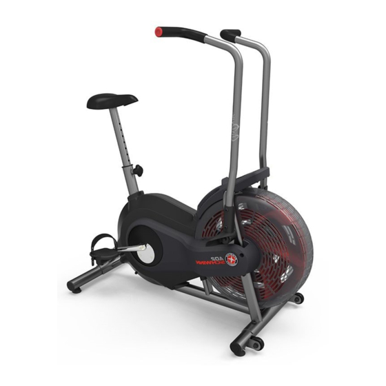
Schwinn Airdyne AD2 Assembly Manual
Assembly and owner's manual
Hide thumbs
Also See for Airdyne AD2:
- User manual ,
- Service manual (31 pages) ,
- Assembly manual / owner's manual (28 pages)

Related Manuals for Schwinn Airdyne AD2


Summary of Contents for Schwinn Airdyne AD2
- Page 1 Manual en Español Latino Americano: ASSEMBLY MANUAL / OWNER’S MANUAL http://www.schwinnfitness.com...
-
Page 2: Table Of Contents
Printed in China | © 2011 Nautilus, Inc., All rights reserved. ™ and ® indicate a trademark or registered trademark. Nautilus, Inc. (www.NautilusInc.com) trademarks include NAUTILUS®, BOWFLEX®, SCHWINN®, UNIVERSAL® and AIRDYNE® and respective logos. Other trademarks are the property of their respective... -
Page 3: Important Safety Instructions - Assembly
IMpORTANT SAfETY INSTRUCTIONS — ASSEMBLY This icon means a potentially hazardous situation which, if not avoided, could result in death or serious injury. Obey the following warnings: Read and understand all warnings on this machine. Carefully read and understand the Assembly instructions. •... -
Page 4: Safety Warning Labels / Serial Number
SAfETY WARNINg LABELS ANd SERIAL NUMBER • • • • 250lbs. (113kg). • • • • • • 250lbs. (113kg). • •... -
Page 5: Specifications
SpECIfICATIONS Maximum User Weight: 250 lbs. (113 kg) Power Requirements: 2 AA batteries (LR6) - not included Operational Voltage: 1.0 - 3.3VDC 50” (127 cm) 46” (117 cm) 25” (63.5 cm) Before Assembly Select the area where you are going to set up and operate your machine. For safe operation, the location must be on a hard, level surface. -
Page 6: Parts
pARTS Item Description Item Description Main Frame Foot Peg, Left Front Stabilizer Handlebar, Right Rear Stabilizer Handlebar, Left Pedal, Right Console Pedal, Left Seat Foot Peg, Right Seat Post... -
Page 7: Hardware
HARdWARE / TOOLS Item Description Button Head Hex Screw M8 x 20 Curved Washer M8 Lock Washer M8 Tools Included Not Included 6 mm (recommended) -
Page 8: Assembly
ASSEMBLY 1. Attach Stabilizers to Frame Assembly 6 mm... - Page 9 2. Attach Pedals Note: The Left Pedal is reverse-threaded. Be sure to attach Pedals on the proper side of the Bike. Orientation is based from a seated position on the bike. The Left Pedal has an “L”, the Right Pedal an “R”.
- Page 10 3. Attach Foot Pegs and Handlebar Arms 6 mm...
- Page 11 4. Install batteries in Console Note: The console uses AA size batteries (LR6), which are not included. Make sure that the batteries point in the direction of the +/– indicators in the battery bay.
- Page 12 5. Attach the Console and Connect the Console Cable NOTICE: Do not crimp Console Cable.
- Page 13 6. Attach Seat to Seat Post and Install on Frame Assembly Note: Hardware is pre-installed on the seat and not on the hardware card. NOTICE: Be sure the Seat is straight and tighten the hardware. Make sure the adjustment knob (12a) engages the holes in the Seat Post. 7.
-
Page 14: Leveling The Bike
BEfORE YOU START Leveling Your Machine If your workout area is uneven, you must level your machine. To adjust: Loosen the upper locking nut. Turn the leveler to adjust the height. Tighten the upper locking nut to lock the leveler. Do not adjust the levelers to such a height that they detach or unscrew from the machine. -
Page 15: Important Safety Instructions - Owner's
IMpORTANT SAfETY INSTRUCTIONS This icon means a potentially hazardous situation which, if not avoided, could result in death or serious injury. Before using this equipment, obey the following warnings: Read and understand the complete Manual. Keep the Manual for future reference. Read and understand all warnings on this machine. -
Page 16: Features
fEATURES Console Pedals Handlebars Adjustable Seat Assembly Fan Assembly Foot Rests Stabilizers Air Vents Transport Wheels Magazine Holder Levelers Battery Bay... -
Page 17: Console Features
Console Features The Console provides information about your workout on the display screen. You can also use the button to get access to information about console settings. Front Back Battery bay Cable connector START/RESET Start Reset WARNING: If you feel any unusual pain, shortness of breath or dizziness, consult your physician. - Page 18 LCD Display Data The console display shows each workout measurement in sequence for 5 seconds: Time Calories Distance Speed Pedal revolutions Numeric display Time The TIME display field shows the time count in the workout. The maximum display is 99:59. If the time count is more, the display starts again at 0:00.
-
Page 19: Operations
OpERATIONS What to Wear Wear rubber-soled athletic shoes. You will need the appropriate clothes for exercise that allow you to move freely. How Often Should You Exercise Consult a physician before you start an exercise program. Stop exercising if you feel pain or tightness in your chest, become short of breath, or feel faint. -
Page 20: Workout Mode
Workout Mode The Console starts Workout Mode if the button is pushed, or if it receives a signal from the RPM sensor as a result of pedaling the machine. The Time starts to count up from 0:00. Note: If the battery level is low, the Console display shows “Batt” for 10 seconds or until the button is pushed. -
Page 21: Service Mode
SERvICE MOdE Service Mode lets you set the units of measure to either English or Metric, see machine statistics and firmware version (for technician use only). When the Console is in Workout Mode or Pause Mode, push and hold down the button for 5 seconds to go into Service Mode. -
Page 22: Maintenance
MAINTENANCE Read all maintenance instructions fully before you start any repair work. In some conditions, an assistant is necessary to do the necessary tasks. Equipment must be regularly examined for damage and repairs. The owner is responsible to make sure that regular maintenance is done. Worn, damaged or loose components must be repaired or replaced immediately. - Page 23 Maintenance Parts Console Crank Arms Speed Sensor Magnet Handlebars Crank Covers Data Cable Fan Assembly Pedals RPM Sensor Fan Assembly Covers Shroud, Right Levelers Footpegs Shroud, Left Seat Arm Pivots M Drive Pulley Seat Post Connector Arms Drive Belt Adjustment Knob...
-
Page 24: Replacing The Batteries
Replacing the Console Batteries The Console display will show “Batt” during power up if the battery level is low. When replacing the batteries, make sure the batteries point in the +/– direction shown in the battery bay. Note: The console uses AA size batteries (LR6). Do not mix old and new batteries. -
Page 25: Troubleshooting
TROUBLESHOOTINg Condition/Problem Things to Check Solution Console will not power up/turn Batteries Make sure batteries are on/start installed correctly. If batteries are correctly installed, replace with a set of new batteries. Check data cable integrity All wires in cable should be intact. - Page 26 Check RPM Sensor (requires RPM sensor should be aligned shroud removal) with magnet and connected to data cable. Realign sensor if necessary. Replace if there is any damage to the sensor or the connecting wire. Console shuts off (enters sleep Check data cable integrity All wires in the cable should be mode) while in use...
- Page 28 Nautilus Bowflex Schwinn fitness Universal ® ® ® ® 004-4565.060211.A...
Need help?
Do you have a question about the Airdyne AD2 and is the answer not in the manual?
Questions and answers