Table of Contents
Advertisement
Quick Links
PARTS AND OPERATION MANUAL
PARTS AND OPERATION MANUAL
Table of Contents
MODEL DCA-150SSKII
PORTABLE GENERATOR
MQ POWER
Revision #2 (05/08/01)
MULTIQUIP INC.
18910 WILMINGTON AVE.
CARSON, CALIFORNIA 90746 FAX: 800-672-7877
310-537-3700
800-421-1244
FAX: 310-537-3927
E-mail:mq@multiquip.com
PARTS DEPARTMENT:
800-427-1244
SERVICE DEPARTMENT:
800-835-2551
FAX: 310-638-8046
•
www:multiquip.com
Advertisement
Table of Contents
Troubleshooting

Related Manuals for MQ Power DCA-150SSKII


Summary of Contents for MQ Power DCA-150SSKII
- Page 1 PARTS AND OPERATION MANUAL PARTS AND OPERATION MANUAL Table of Contents MQ POWER MODEL DCA-150SSKII PORTABLE GENERATOR Revision #2 (05/08/01) MULTIQUIP INC. PARTS DEPARTMENT: 18910 WILMINGTON AVE. 800-427-1244 CARSON, CALIFORNIA 90746 FAX: 800-672-7877 SERVICE DEPARTMENT: 310-537-3700 800-421-1244 800-835-2551 FAX: 310-537-3927 FAX: 310-638-8046 •...
- Page 2 Table of Contents PAGE 2 —DCA-150SSKII— PARTS AND OPERATION MANUAL — REV. #2 (05/08/01)
-
Page 3: Dca-150Sskii — Parts And Operation Manual— Rev. #1 (05/08/01)
PARTS DEPARTMENT 800/427-1244 or 310/537-3700 FAX: 800/672-7877 or 310/637-3284 SERVICE DEPARTMENT 800/835-2551 or 310/537-3700 FAX: 310/638-8046 WARRANTY DEPARTMENT 800/835-2551 or 310/537-3700 FAX: 310/638-8046 MAIN 800/421-1244 or 310/537-3700 FAX: 310/537-3927 DCA-150SSKII — PARTS AND OPERATION MANUAL— REV. #1 (05/08/01) — PAGE 3... -
Page 4: Table Of Contents
Generator Start-Up Procedure (Auto) ....50 Generator Shut-Down Procedure ......51 Maintenance ............ 51-53 Troubleshooting (Engine) ......... 54-55 Troubleshooting (Generator/Engine) .....56 Troubleshooting (MPEC) ........57 Explanation Of Codes In Remarks Column ...58 Suggested Spare Parts ..........59 PAGE 4 —DCA-150SSKII— PARTS AND OPERATION MANUAL — REV. #2 (05/08/01) -
Page 5: Parts Ordering Procedures
10+ line items. Toll-free FAX: 800/6-PARTS-7 • 800-672-7877 *DISCOUNTS ARE SUBJECT TO CHANGE* Fax order discount and UPS special programs revised June 1, 1995 DCA-150SSKII — PARTS AND OPERATION MANUAL— REV. #1 (05/08/01) — PAGE 5... -
Page 6: Rules For Safe Operation
An explosion or fire could result causing severe bodily harm or even death. Topping-off to filler port is dangerous, as it tends to spill fuel. PAGE 6 —DCA-150SSKII— PARTS AND OPERATION MANUAL — REV. #2 (05/08/01) - Page 7 Make sure the power connecting cables are securely connected to the generator’s output terminals. Insufficient tightening of the terminal connections may cause damage to the generator and electrical shock. DCA-150SSKII — PARTS AND OPERATION MANUAL— REV. #1 (05/08/01) — PAGE 7...
- Page 8 When loading the generator on a truck, be sure to use the front and back frame bars as a means to secure the generator during transport. PAGE 8 —DCA-150SSKII— PARTS AND OPERATION MANUAL — REV. #2 (05/08/01)
-
Page 9: Rules For Safe Operation
Also know the phone numbers of the nearest ambulance , DO NOT pour waste, oil, coolant or fuel directly onto doctor and fire department . the ground, down a drain or into any water source. DCA-150SSKII — PARTS AND OPERATION MANUAL— REV. #1 (05/08/01) — PAGE 9... -
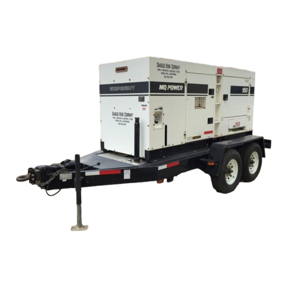
Page 10: Towing
Also check the tire tread wear on both DO NOT transport generator with fuel in tank. vehicles. ALWAYS make sure the trailer is equipped with a "Safety Chain". Figure 1. Generator with Trailer PAGE 10 —DCA-150SSKII— PARTS AND OPERATION MANUAL — REV. #2 (05/08/01) - Page 11 5. Frame Width - This measurement is from fender to fender. 6. Jack Stand - Trailer support device with maximum pound requirement from the tongue of the trailer. DCA-150SSKII — PARTS AND OPERATION MANUAL— REV. #1 (05/08/01) — PAGE 11...
-
Page 12: Trailer Specifications
" 6 " 6 " 7 " 4 " 4 " 2 " 3 " 8 " 3 " 8 " 3 " 4 " 6 " 4 " 6 PAGE 12 —DCA-150SSKII— PARTS AND OPERATION MANUAL — REV. #2 (05/08/01) -
Page 13: Trailer Specifications
" 7 " 3 X " " 7 " 3 X " " 7 " 3 X " " 7 X " " 7 X " " 7 DCA-150SSKII — PARTS AND OPERATION MANUAL— REV. #1 (05/08/01) — PAGE 13... -
Page 14: Trailer Braking System
7. Replace the adjusting hole cover and lower the trailer to the ground. 8. Repeat steps 1 through 6 on the remaining brakes. PAGE 14 —DCA-150SSKII— PARTS AND OPERATION MANUAL — REV. #2 (05/08/01) -
Page 15: Trailer Braking System
Brake section. Refer to Table 6 for hydraulic brake troubleshooting lines should be periodically checked for cracks, kinks, or guidelines. blockage. Figure 3. Hydraulic Brake Components DCA-150SSKII — PARTS AND OPERATION MANUAL— REV. #1 (05/08/01) — PAGE 15... -
Page 16: Trailer Tires & Suspension
CAUTION: NOTE ALWAYS wear safety glasses when removing Figure 4. Suspension Components or installing force fitted parts. Failure to comply may result in serious injury. PAGE 16 —DCA-150SSKII— PARTS AND OPERATION MANUAL — REV. #2 (05/08/01) -
Page 17: Trailer Tires & Suspension
Check all wheel lug nuts periodically for continued safe operaion. Figure 5. Lug Nut Tightening Sequence NOTE NEVER use an pneumatic air gun to tighten wheel lug nuts. DCA-150SSKII — PARTS AND OPERATION MANUAL— REV. #1 (05/08/01) — PAGE 17... - Page 18 Table of Contents DCA-150SSKII — TRAILER WIRING DIAGRAMS NOTE: LIGHTS ARE ORIENTED FROM THE DRIVER’S SEAT PAGE 18 —DCA-150SSKII— PARTS AND OPERATION MANUAL — REV. #2 (05/08/01)
- Page 19 Table of Contents DCA-150SSKII — TRAILER-BRAKE TROUBLESHOOTING . r i l l u l i o DCA-150SSKII — PARTS AND OPERATION MANUAL— REV. #1 (05/08/01) — PAGE 19...
- Page 20 Table of Contents DCA-150SSKII — TRAILER-BRAKE TROUBLESHOOTING . y l l l i f PAGE 20 —DCA-150SSKII— PARTS AND OPERATION MANUAL — REV. #2 (05/08/01)
-
Page 21: Operation And Safety Decals
DCA-150SSKII — OPERATION AND SAFETY DECALS Machine Safety Decals The DCA-150SSKII generator is equipped with a number of safety decals. These decals are provided for operator safety and maintenance information. The illustration below and on the preceding page shows these decals as they appear on the machine. -
Page 22: Operation And Safety Decals
Table of Contents DCA-150SSKII — OPERATION AND SAFETY DECALS PAGE 22 —DCA-150SSKII— PARTS AND OPERATION MANUAL — REV. #2 (05/08/01) -
Page 23: Specifications
Table of Contents DCA-150SSKII — SPECIFICATIONS t i l t i l DCA-150SSKII — PARTS AND OPERATION MANUAL— REV. #1 (05/08/01) — PAGE 23... -
Page 24: General Information
The basic controls and indicators for the DCA-150SSKII Control Box generator are addressed on the following pages. The “Control Box” is provided with the following: " Main Circuit Breaker 400 amps " Over-Current Relay PAGE 24 —DCA-150SSKII— PARTS AND OPERATION MANUAL — REV. #2 (05/08/01) - Page 25 NOTE PAGE DCA-150SSKII — PARTS AND OPERATION MANUAL— REV. #1 (05/08/01) — PAGE 25...
-
Page 26: Major Components
Table of Contents DCA-150SSKII — MAJOR COMPONENTS Figure 6. Major Components PAGE 26 —DCA-150SSKII— PARTS AND OPERATION MANUAL — REV. #2 (05/08/01) -
Page 27: Dimensions (Top, Side And Rear)
Table of Contents DCA-150SSKII — DIMENSIONS (TOP, SIDE, AND REAR) Figure 7. Dimensions DCA-150SSKII — PARTS AND OPERATION MANUAL— REV. #1 (05/08/01) — PAGE 27... -
Page 28: Control Panel
Table of Contents DCA-150SSKII — CONTROL PANEL Figure 8. Control Panel PAGE 28 —DCA-150SSKII— PARTS AND OPERATION MANUAL — REV. #2 (05/08/01) -
Page 29: Control Panel
This is considered a major fault. Engine Running – Indicates that engine is running at a safe operating speed. Figure 9. MPEC Module DCA-150SSKII — PARTS AND OPERATION MANUAL— REV. #1 (05/08/01) — PAGE 29... -
Page 30: Engine Operating Panel
Table of Contents DCA-150SSKII — ENGINE OPERATING PANEL Figure 10. Engine Operating Panel PAGE 30 —DCA-150SSKII— PARTS AND OPERATION MANUAL — REV. #2 (05/08/01) -
Page 31: Engine Operating Panel
C. Low Fuel Level Lamp – When this lamp is ON, it is time to stop the engine and add fuel. Remember to let the engine cool before adding fuel. DCA-150SSKII — PARTS AND OPERATION MANUAL— REV. #1 (05/08/01) — PAGE 31... -
Page 32: Output Terminal Panel
GFCI function. The over switch to the U or W to read the output. receptacle should be tested at least once a month. FIGURE 12. GFCI Test Button PAGE 32 —DCA-150SSKII— PARTS AND OPERATION MANUAL — REV. #2 (05/08/01) - Page 33 Table of Contents DCA-150SSKII — OUTPUT TERMINAL PANEL OVERVIEW NOTE Legs O and Ground are considered Bonded Grounds. FIGURE 14. Output Terminal Panel DCA-150SSKII — PARTS AND OPERATION MANUAL— REV. #1 (05/08/01) — PAGE 33...
- Page 34 If the circuit breaker can not be reset, the reset button on the over current relay must be pressed. The over current relay is located in the control box. PAGE 34 —DCA-150SSKII— PARTS AND OPERATION MANUAL — REV. #2 (05/08/01)
- Page 35 FIGURE 15. Voltage Selector Switch 240/120V Single Phase Position FIGURE 16. AC Voltmeter FIGURE 17. AC Voltmeter Change-over switch Guage (Reading the W-U leg on (Volt reading on W-U Lug) the outputerminal panel) DCA-150SSKII — PARTS AND OPERATION MANUAL— REV. #1 (05/08/01) — PAGE 35...
- Page 36 FIGURE 22. Voltage Selector Switch 480/277V Three Phase FIGURE 20. Voltage Selector Switch 240/120V Single Phase Position Position FIGURE 23. Hard Wire Hook-up at 480/240V Position FIGURE 21. Hard Wire Hook-up at 240/120V Position PAGE 36 —DCA-150SSKII— PARTS AND OPERATION MANUAL — REV. #2 (05/08/01)
- Page 37 (See Figure 25). FIGURE 26. Hard Wire Hook-up for Three Phase 480V, 440V, FIGURE 28. Hard Wire Hook-up for Single Phase 277V, 254V, or 416V or 240V DCA-150SSKII — PARTS AND OPERATION MANUAL— REV. #1 (05/08/01) — PAGE 37...
- Page 38 (See Figure 30). FIGURE 33. Hard Wire Hook-up for Single Phase 139V, 127V, FIGURE 31. Hard Wire Hook-up for Three Phase 240V, 220V, or 120V or 208V PAGE 38 —DCA-150SSKII— PARTS AND OPERATION MANUAL — REV. #2 (05/08/01)
-
Page 39: Output Terminal Panel
36 below, use the Voltage Regulator Knob to fine tune to 240V. (See Figure 35). FIGURE 36. Hard Wire Hook-up for Single Phase 240 volt DCA-150SSKII — PARTS AND OPERATION MANUAL— REV. #1 (05/08/01) — PAGE 39... -
Page 40: Installation
DO NOT cover ventilation areas on the enclosure, covering the ventilation grids will cause the engine to over heat. NOTE When connecting the generator to any buildings electrical system ALWAYS consult with a licensed electrician. PAGE 40 —DCA-150SSKII— PARTS AND OPERATION MANUAL — REV. #2 (05/08/01) -
Page 41: Installation
Table of Contents DCA-150SSKII — INSTALLATION Figure 38. Typical Generator Grounding Application CAUTION : Always check Local, State, and Federal laws before grounding generator set. DCA-150SSKII — PARTS AND OPERATION MANUAL— REV. #1 (05/08/01) — PAGE 41... -
Page 42: Pre-Setup
. t f . t f . t f . t f . t f . t f . t f . t f . t f a t l PAGE 42 —DCA-150SSKII— PARTS AND OPERATION MANUAL — REV. #2 (05/08/01) - Page 43 Komatsu Engine Owner's Manual. ° 4 ° 3 ° 0 ° 5 ° 3 ° 5 ° 5 ° 5 ° 5 ) ° DCA-150SSKII — PARTS AND OPERATION MANUAL— REV. #1 (05/08/01) — PAGE 43...
- Page 44 50%. contact may result in poor starting or malfunctions. Always keep the terminals firmly tightened. Coating the terminals with a thin film of grease will help to inhibit corrosion. PAGE 44 —DCA-150SSKII— PARTS AND OPERATION MANUAL — REV. #2 (05/08/01)
-
Page 45: Pre-Setup
2. Place a small amount of grease around both battery terminals. This will ensure a good connection and will help prevent corrosion around the battery terminals. DCA-150SSKII — PARTS AND OPERATION MANUAL— REV. #1 (05/08/01) — PAGE 45... -
Page 46: Load Application
(kVA) given When calculating the power requirements for 3-phase on the equipment nameplate, approximate power use the following equation: output may be determined by multiplying voltage by amperage by PAGE 46 —DCA-150SSKII— PARTS AND OPERATION MANUAL — REV. #2 (05/08/01) -
Page 47: Generator Start-Up Procedure (Manual)
G.F.C.I. circuit breakers (Figure 42) to the “OFF” position prior to starting the engine. Figure 44. Battery Connections Figure 42. Main, GFCI and Load Circuit Breakers DCA-150SSKII — PARTS AND OPERATION MANUAL— REV. #1 (05/08/01) — PAGE 47... - Page 48 10. If the generator is equipped without the engine throttle lever, set the idle control switch to the "ON" position. (See figure 52) Figure 48. Off/Manual/Auto Switch (Manual) Figure 52. Idle Control (ON) PAGE 48 —DCA-150SSKII— PARTS AND OPERATION MANUAL — REV. #2 (05/08/01)
-
Page 49: Generator Start-Up Procedure (Manual)
When a load is applied, this meter will indicate the amount of current that the load is drawing from the generator’s alternator. Figure 59. Engine Tachometer Figure 56. Ammeter (No Load) DCA-150SSKII — PARTS AND OPERATION MANUAL— REV. #1 (05/08/01) — PAGE 49... -
Page 50: Generator Start-Up Procedure (Auto)
20. The generator will run until manually stopped or an abnormal condition occurs. Figure 62. Off/Manual/Auto Switch (Manual) 3. Continue to follow the steps outline in the manual start- up procedure (start at step 9, page 48). PAGE 50 —DCA-150SSKII— PARTS AND OPERATION MANUAL — REV. #2 (05/08/01) -
Page 51: Generator Shut-Down Procedure
4. Let the engine cool by running it for 3-5 minutes with no load applied. 5. Place the Off/Manual/Auto Switch (Figure 65) in the "OFF/ RESET" position. Figure 65. Off/Manual Auto Switch (OFF) DCA-150SSKII — PARTS AND OPERATION MANUAL— REV. #1 (05/08/01) — PAGE 51... -
Page 52: Maintenance
If engine is operating in very dusty and dry grass conditions, a clogged air cleaner will result in high fuel consumption, loss of power and excessive carbon buildup in the combustion chamber. PAGE 52 —DCA-150SSKII— PARTS AND OPERATION MANUAL — REV. #2 (05/08/01) -
Page 53: Maintenance
. y l t l i f r i f . y l DCA-150SSKII — PARTS AND OPERATION MANUAL— REV. #1 (05/08/01) — PAGE 53... -
Page 54: Troubleshooting (Engine)
, t l i l y n i l . t s u f l o i t i r i PAGE 54 —DCA-150SSKII— PARTS AND OPERATION MANUAL — REV. #2 (05/08/01) -
Page 55: Troubleshooting (Engine)
? l i n i l c i f t l i f c i f c i f c i f n i l , t l DCA-150SSKII — PARTS AND OPERATION MANUAL— REV. #1 (05/08/01) — PAGE 55... -
Page 56: Troubleshooting (Generator/Engine)
- , t i i t c i t c i t c e t l e t l e t l e t l PAGE 56 —DCA-150SSKII— PARTS AND OPERATION MANUAL — REV. #2 (05/08/01) -
Page 57: Troubleshooting (Mpec)
DCA-150SSKII — PARTS AND OPERATION MANUAL— REV. #1 (05/08/01) — PAGE 57... -
Page 58: Explanation Of Codes In Remarks Column
, belong to the same assembly or kit. NOTE If more than one of the same reference number is listed, the last one listed indicates newest (or latest) part available. PAGE 58 —DCA-150SSKII— PARTS AND OPERATION MANUAL — REV. #2 (05/08/01) -
Page 59: Suggested Spare Parts
1 ..0602122037 ..OIL PRESSURE GAUGE 1 ..0602122251 ..OIL SHUT-DOWN SENDING UNIT 1 ..0602123250 ..WATER TEMPERATURE SENDING UNIT 3 ..0601822034 ..RECEPTACLE, CS 6369 250V, 50 AMPS DCA-150SSKII — PARTS AND OPERATION MANUAL— REV. #1 (05/08/01) — PAGE 59... - Page 60 Table of Contents DCA-150SSKII— GENERATOR ASSY. GENERATOR ASSY. PAGE 60 —DCA-150SSKII— PARTS AND OPERATION MANUAL — REV. #2 (05/08/01)
- Page 61 HEX HEAD BOLT ......12 ..REPLACES 0012110030 030210250 LOCK WASHER ......12 ..REPLACES 0042510000 8131332003 COVER, FAN 0605000063 RUBBER SUSPENSION 0030016000 HEX NUT 0040016000 LOCK WASHER DCA-150SSKII — PARTS AND OPERATION MANUAL— REV. #1 (05/08/01) — PAGE 61...
- Page 62 Table of Contents DCA-150SSKII — CONTROL BOX ASSY. CONTROL BOX ASSY. PAGE 62 —DCA-150SSKII— PARTS AND OPERATION MANUAL — REV. #2 (05/08/01)
- Page 63 BRACKET, SELECTOR SWITCH 1 0021304020 MACHINE SCREW 0021306020 MACHINE SCREW 0021306020 MACHINE SCREW 011008020 HEX HEAD BOLT ......2 ..REPLACES 0017108020 020108060 HEX NUT ........2 ..REPLACES 0207008000 DCA-150SSKII — PARTS AND OPERATION MANUAL— REV. #1 (05/08/01) — PAGE 63...
- Page 64 Table of Contents DCA-150SSKII— CONTROL BOX ASSY. CONTROL BOX ASSY. PAGE 64 —DCA-150SSKII— PARTS AND OPERATION MANUAL — REV. #2 (05/08/01)
- Page 65 HEX HEAD BOLT ........8 .... REPLACES 0017108020 8361827504 PANEL, CONTROL BOX 011008020 HEX HEAD BOLT ........8 .... REPLACES 0017108020 011008020 HEX HEAD BOLT ........4 .... REPLACES 0017108020 DCA-150SSKII — PARTS AND OPERATION MANUAL— REV. #1 (05/08/01) — PAGE 65...
- Page 66 Table of Contents DCA-150SSKII— ENGINE & RADIATOR ASSY. ENGINE & RADIATOR ASSY. PAGE 66 —DCA-150SSKII— PARTS AND OPERATION MANUAL — REV. #2 (05/08/01)
- Page 67 DRAIN PLUG 011208025 HEX HEAD BOLT ......2 ..REPLACES 0017108025 0130008000 ELBOW JOINT, 3/4 0134308100 LONG NIPPLE 0603325017 VALVE ..........1 ..BBS22020 0602022294 HOSE JOINT 0265800850 DRAIN HOSE DCA-150SSKII — PARTS AND OPERATION MANUAL— REV. #1 (05/08/01) — PAGE 67...
- Page 68 Table of Contents DCA-150SSKII— ENGINE & RADIATOR ASSY. ENGINE & RADIATOR ASSY. PAGE 68 —DCA-150SSKII— PARTS AND OPERATION MANUAL — REV. #2 (05/08/01)
- Page 69 HOSE 0605515013 HOSE BAND 0193600450 HOSE 0193600800 HOSE 0268200900 HOSE 0605515132 HOSE BAND 8302256104 CLAMPER ROD 8152256104 CLAMPER ROD 012210020 HEX HEAD BOLT ......3 ..REPLACES 0017110020 DCA-150SSKII — PARTS AND OPERATION MANUAL— REV. #1 (05/08/01) — PAGE 69...
- Page 70 Table of Contents DCA-150SSKII — ENGINE OPERATING PANEL ASSY. ENGINE OPERATING PANEL ASSY. PAGE 70 —DCA-150SSKII— PARTS AND OPERATION MANUAL — REV. #2 (05/08/01)
- Page 71 0207006000 HEX NUT 952404470 PLAIN WASHER ......2 ..REPLACES 0041206000 C0355200204 ROD GUIDE 0017112025 HEX HEAD BOLT C0484000303 SUPPORT LEG 0017110025 HEX HEAD BOLT 0207010000 HEX NUT DCA-150SSKII — PARTS AND OPERATION MANUAL— REV. #1 (05/08/01) — PAGE 71...
- Page 72 Table of Contents DCA-150SSKII — ENGINE OPERATING PANEL ASSY. ENGINE OPERATING PANEL ASSY. PAGE 72 —DCA-150SSKII— PARTS AND OPERATION MANUAL — REV. #2 (05/08/01)
- Page 73 HEX HEAD BOLT ......2 .....REPLACES 0017106020 8131865303 COVER 012212045 HEX HEAD BOLT ......2 .....REPLACES 0010012045 031112230 PLAIN WASHER ......2 .....REPLACES 0041212000 0805009804 RUBBER WASHER 0030012000 HEX NUT DCA-150SSKII — PARTS AND OPERATION MANUAL— REV. #1 (05/08/01) — PAGE 73...
- Page 74 Table of Contents DCA-150SSKII — BATTERY ASSY. BATTERY ASSY. PAGE 74 —DCA-150SSKII— PARTS AND OPERATION MANUAL — REV. #2 (05/08/01)
- Page 75 HEX HEAD BOLT ......1 ..REPLACES 0010012025 0040012000 LOCK WASHER 031112230 PLAIN WASHER ......1 ..REPLACES 0041212000 0040512000 TOOTHED WASHER 0845040414 TERMINAL CAP + 0845041304 TERMINAL CAP - DCA-150SSKII — PARTS AND OPERATION MANUAL— REV. #1 (05/08/01) — PAGE 75...
- Page 76 Table of Contents DCA-150SSKII — MUFFLER ASSY. MUFFLER ASSY. PAGE 76 —DCA-150SSKII— PARTS AND OPERATION MANUAL — REV. #2 (05/08/01)
- Page 77 0010112050 HEX HEAD BOLT 0030012000 HEX NUT 031112230 PLAIN WASHER ......8 ..REPLACES 0041212000 8252354004 COVER C0334200104 SHEET 011008020 HEX HEAD BOLT ......4 ..REPLACES 0017108020 DCA-150SSKII — PARTS AND OPERATION MANUAL— REV. #1 (05/08/01) — PAGE 77...
- Page 78 Table of Contents DCA-150SSKII — FUEL TANK ASSY. FUEL TANK ASSY. PAGE 78 —DCA-150SSKII— PARTS AND OPERATION MANUAL — REV. #2 (05/08/01)
- Page 79 0802011104 PLUG 0150000018 O RING 0191301100 SUCTION HOSE 0191301200 RETURN HOSE 0191001750 RETURN HOSE 0605515014 HOSE BAND 0605515013 HOSE BAND 0605503009 FUEL SENSOR 0802120604 PACKING 0845039604 RUBBER SEAL DCA-150SSKII — PARTS AND OPERATION MANUAL— REV. #1 (05/08/01) — PAGE 79...
- Page 80 WHEN ORDERING ANY PAINTED PANEL TO INDICATE COLOR OF UNIT: 5 -BLACK 1-ORANGE 6 -CATERPILLAR YELLOW 2-WHITE 7 -CATO GOLD 3 -SPECTRUM GRAY 8 -RED 4 -SUNBELT GREEN THE SERIAL NUMBER MAY BE REQUIRED. PAGE 80 —DCA-150SSKII— PARTS AND OPERATION MANUAL — REV. #2 (05/08/01)
- Page 81 DOOR, REAR FRAME C0444200413 DOOR, REAR FRAME B9114000102 DOOR HANDLE 0021806016 MACHINE SCREW 0030006016 HEX, NUT 8255146104 DOOR ROD 8255146204 DOOR ROD 0845050704 STAY 0207006000 HEX, NUT 8165157004 WINDOW PLATE DCA-150SSKII — PARTS AND OPERATION MANUAL— REV. #1 (05/08/01) — PAGE 81...
- Page 82 WHEN ORDERING ANY PAINTED PANEL TO INDICATE COLOR OF UNIT: 5 -BLACK 1-ORANGE 6 -CATERPILLAR YELLOW 2-WHITE 7 -CATO GOLD 3 -SPECTRUM GRAY 8 -RED 4 -SUNBELT GREEN THE SERIAL NUMBER MAY BE REQUIRED. PAGE 82 —DCA-150SSKII— PARTS AND OPERATION MANUAL — REV. #2 (05/08/01)
- Page 83 HINGE 0845045004 WASHER 0845047004 HINGE 0845045004 WASHER 011008020 HEX. HEAD BOLT ....... 16 ..REPLACES 0017108020 0601850057 RUBBER CUSHION 0021008025 MACHINE SCREW 0845031504 B9511200003 EMBLEM 0021106016 MACHINE SCREW DCA-150SSKII — PARTS AND OPERATION MANUAL— REV. #1 (05/08/01) — PAGE 83...
- Page 84 Table of Contents DCA-150SSKII — RUBBER SEALS ASSY. RUBBER SEALS ASSY. PAGE 84 —DCA-150SSKII— PARTS AND OPERATION MANUAL — REV. #2 (05/08/01)
- Page 85 RUBBER SEAL 0228900730 RUBBER SEAL 0228901080 RUBBER SEAL 0229201200 RUBBER SEAL Full View 0228800650 RUBBER SEAL 0228801045 RUBBER SEAL 0229201190 RUBBER SEAL 0228100320 RUBBER SEAL 0228100540 RUBBER SEAL DCA-150SSKII — PARTS AND OPERATION MANUAL— REV. #1 (05/08/01) — PAGE 85...
-
Page 86: Name Plate And Decals
Table of Contents DCA-150SSKII — NAME PLATE AND DECALS NAME PLATE AND DECALS PAGE 86 —DCA-150SSKII— PARTS AND OPERATION MANUAL — REV. #2 (05/08/01) - Page 87 DECAL;WARNING ..........1 ....B91110030 B9511100404 DECAL;WARNING ..........1 ....B91110040 B9531100504 DECAL; WARNING ..........1 .... B93110050 B9531100604 DECAL; WARNING ..........1 .... B93110060 5-10 C0551001004 DECAL; NOTE ............ 1 .... C05100100 DCA-150SSKII — PARTS AND OPERATION MANUAL— REV. #1 (05/08/01) — PAGE 87...
- Page 88 Table of Contents DCA-150SSKII — NAME PLATE AND DECALS NAME PLATE AND DECALS PAGE 88 —DCA-150SSKII— PARTS AND OPERATION MANUAL — REV. #2 (05/08/01)
-
Page 89: Name Plate And Decals
DECAL; MQ ............1 .... S-3057 B9504000304 DECAL; CAUTION ..........1 .... B90400030 C0561100402 STRIPE C0561101203 STRIPE C0561100204 STRIPE C0561100603 STRIPE C0561102604 STRIPE 9-10 C0561101003 STRIPE 9-11 C0561100103 STRIPE DCA-150SSKII — PARTS AND OPERATION MANUAL— REV. #1 (05/08/01) — PAGE 89... -
Page 90: Terms And Conditions Of Sale — Parts
RMA. products on the face hereof. A copy of the Return Material Authorization must accompany the return shipment. PAGE 90 —DCA-150SSKII— PARTS AND OPERATION MANUAL — REV. #2 (05/08/01) - Page 91 NOTE PAGE DCA-150SSKII — PARTS AND OPERATION MANUAL— REV. #1 (05/08/01) — PAGE 91...
- Page 92 FAX: 310/638-8046 WARRANTY DEPARTMENT 800/835-2551 or 310/537-3700 FAX: 310/638-8046 MAIN 800/421-1244 or 310/537-3700 FAX: 310 - 537-3927 Manufactured for Multiquip Inc. DENYO, MANUFACTURING, CO., USA MULTIQUIP INC. POST OFFICE BOX 6254 CARSON, CA 90749 310-537-3700 • 800-421-1244 FAX: 310-537-3927 E-MAIL: mq@multiquip.com WWW: multiquip.com...
Need help?
Do you have a question about the DCA-150SSKII and is the answer not in the manual?
Questions and answers