Table of Contents
Advertisement
Quick Links
OPERATION MANUAL
WHISPERWATT™ SERIES
MODEL DCA150SSJU4F2
MODEL DCA150SSJU4F3
60Hz GENERATORS
(JOHN DEERE 6068HFG05 DIESEL ENGINE)
INSTRUCTION MANUAL NO. M3844300704/DCA150SSJU4F2
INSTRUCTION MANUAL NO. M3844301204/DCA150SSJU4F3
To find the latest revision of this publication or
associated parts manual, visit our website at:
THIS MANUAL MUST ACCOMPANY THE EQUIPMENT AT ALL TIMES.
Revision #0 (02/16/22)
www.mqpower.com
Advertisement
Table of Contents
Troubleshooting

Related Manuals for MQ Power WHISPERWATT DCA150SSJU4F2


Summary of Contents for MQ Power WHISPERWATT DCA150SSJU4F2
- Page 1 OPERATION MANUAL WHISPERWATT™ SERIES MODEL DCA150SSJU4F2 MODEL DCA150SSJU4F3 60Hz GENERATORS (JOHN DEERE 6068HFG05 DIESEL ENGINE) INSTRUCTION MANUAL NO. M3844300704/DCA150SSJU4F2 INSTRUCTION MANUAL NO. M3844301204/DCA150SSJU4F3 Revision #0 (02/16/22) To find the latest revision of this publication or associated parts manual, visit our website at: www.mqpower.com THIS MANUAL MUST ACCOMPANY THE EQUIPMENT AT ALL TIMES.
-
Page 2: Proposition 65 Warning
PROPOSITION 65 WARNING PAGE 2 — DCA150SSJU4F2/F3 60 HZ GENERATOR • OPERATION MANUAL — REV. #0 (02/16/22) -
Page 3: Table Of Contents
TABLE OF CONTENTS DCA150SSJU4F2/F3 60 Hz Generators Proposition 65 Warning ........... 2 Safety Decals ............4 Safety Information ..........5–10 Specifications ............11 Dimensions ............12–13 Installation ............14–15 General Information ......... 16–17 General Paralleling Information (Option) ..18–20 Major Components ..........21 Engine Control Unit (ECU-845) ...... -
Page 4: Safety Decals
SAFETY DECALS Safety decals are attached to the generator as shown in NOTICE Figure 1. Keep these safety decals clean at all times. When For safety decal part numbers, refer to the associated the safety decals become worn or damaged, contact your parts manual. -
Page 5: Safety Information
SAFETY INFORMATION Do not operate or service the generator before reading the Potential hazards associated with the operation of this entire manual. Safety precautions should be followed at all generator will be referenced with hazard symbols which times when operating this generator. Failure to read and may appear throughout this manual in conjunction with understand the safety messages and operating instructions safety messages. - Page 6 „ NEVER use accessories or attachments that are not being used. The generator should be stored in a clean, dry location out of the reach of children and unauthorized recommended by MQ Power for this generator. Damage to the generator and/or injury to the user may result. personnel.
- Page 7 SAFETY INFORMATION ENGINE SAFETY „ Operation of the generator may create sparks that can start fi res around dry vegetation. A spark arrestor DANGER may be required. The operator should contact local fi re agencies for laws or regulations relating to fi re prevention „...
- Page 8 SAFETY INFORMATION „ State Health Safety Codes and Public Resources „ Refer to the MQ Power trailer manual for additional safety Codes specify that in certain locations, spark arresters information. must be used on internal combustion engines that use „ In order to reduce the possibility of an accident hydrocarbon fuels.
- Page 9 SAFETY INFORMATION „ Raise and lock the trailer wheel stand in the upright „ NEVER use damaged or worn cables or cords when position when towing. connecting equipment to the generator. Inspect the insulation for cuts. „ Place chock blocks underneath the wheels to prevent rolling while parked.
- Page 10 SAFETY INFORMATION „ ALWAYS keep the battery charged. If the battery is not Metal recycling involves the collection of metal from charged, combustible gas will build up. discarded products and its transformation into raw materials to use in manufacturing a new product. „...
- Page 11 NOTES DCA150SSJU4F2/F3 60 HZ GENERATOR • OPERATION MANUAL — REV. #0 (02/16/22) — PAGE 11...
-
Page 12: Specifications
SPECIFICATIONS Table 1. Generator Specifications Model DCA150SSJU4F2 DCA150SSJU4F3 Revolving field, self-ventilated, Type open protected type synchronous generator Armature Connection Star with Neutral Zigzag Phase 3Ø Single Standby Output 132 kW (165 kVA) 95.7 kW Prime Output 120 kW (150 kVA) 87 kW 3Ø... -
Page 13: Dimensions
DIMENSIONS MAXIMUM LIFTING TOP VIEW POINT 16,500 lbs. (7,483 kg) PowerBalance (Option) SIDE VIEW Figure 2. Dimensions PowerBalance (Option) FRONT VIEW Table 3. Dimensions Reference Reference Dimension in. (mm) Dimension in. (mm) Letter Letter 44.29 (1,125) 35.24 (895) 41.34 (1,050) 11.38 (289) 44.29 (1,125) 141.73 (3,600) -
Page 14: Installation
M I N 2 . 4 T . / REFERENCE NEC 250 Figure 3. Typical Generator Grounding Application NOTICE Trailer-mounted generators are the sole responsibility of MQ Power. PAGE 14 — DCA150SSJU4F2/F3 60 HZ GENERATOR • OPERATION MANUAL — REV. #0 (02/16/22) - Page 15 INSTALLATION OUTDOOR INSTALLATION GENERATOR GROUNDING NOTICE Install the generator in an area that is free of debris, bystanders, and overhead obstructions. Make sure the The Occupational Safety and Health Administration generator is on secure, level ground so that it cannot slide (OSHA) and the National Electrical Code (NEC) or shift around.
-
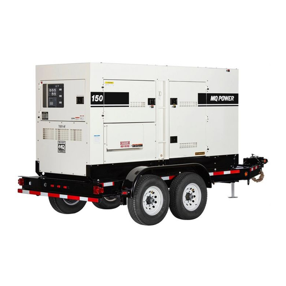
Page 16: General Information
GENERAL INFORMATION GENERAL INFORMATION GENERATOR CONTROL PANEL This generator (Figure 7) is designed as a high-quality, The “Control Panel” is provided with the following: portable (requires a trailer for transport) power source for „ Frequency Meter (Hz) telecom sites, lighting facilities, power tools, submersible pumps, and other industrial and construction machinery. - Page 17 There are four connections of the open delta—A, B, C and D. During steady state loads, the power from the voltage In keeping with MQ Power’s policy of constantly improving regulator is supplied from the parallel connections of A to B, its products, the specifications quoted herein are subject A to D, and C to D.
-
Page 18: General Paralleling Information (Option)
GENERAL PARALLELING INFORMATION (OPTION) The kVAR load sharing is achieved by increasing or NOTICE decreasing the field excitation to the systems’ alternators. When the paralleling option is employed, the Basler As the field excitation of one generator set in a group is DGC-2020HD controller must be installed. - Page 19 GENERAL PARALLELING INFORMATION (OPTION) SEQUENCING The complete password sequence is shown in Figure 4. The set-point for the desired hours until maintenance can NOTICE now be changed. Press edit to save. Ethernet communication is required when the generators are configured for the sequencing mode of operation.
- Page 20 GENERAL PARALLELING INFORMATION (OPTION) Pressing the alarm silence button will stop the toggling NOTICE between the pre-alarm and the overview screen. When connecting load cables to the power distribution Once the overview screen is selected, the maintenance panel be sure to select the correct size of the load interval can be reset by pressing and holding the reset cables to handle full load/amperage of both generators button for 10 seconds.
-
Page 21: Major Components
MAJOR COMPONENTS DCA150SSJU4F2 WHISPERWATT DCA150SSJU4F3 DCA150SSJU4F3 WHISPERWATT O O GND Table 5. Generator Major Components ITEM NO. DESCRIPTION DOC/SCR Assembly Air Filter Assembly °F RPMX10 INCREASE DECREASE OIL PRESS WATER TEMP SPEED VOLTS Integrated Gauge Panel Check ½ ½ Emissions Failure Emissions °F... -
Page 22: Engine Control Unit (Ecu-845)
ENGINE CONTROL UNIT (ECU-845) Series 800 Controller Engine Started °F RPMX10 INCREASE DECREASE OIL PRESS WATER TEMP SPEED ECU Shutdown VOLTS Integrated Gauge Panel ½ ½ Check Emissions Failure °F °F Emissions Failure Regen Pre-Alarm Needed FUEL Regen Inhibit Fuel Series 800 Controller Engine Started Shutdown... -
Page 23: Gauge Unit Assembly (Ecu-670)
GAUGE UNIT ASSEMBLY (ECU-670) RPMX10 °F INCREASE DECREASE OIL PRESS SPEED WATER TEMP ECU VOLTS Integrated Gauge Panel RPMX10 °F ½ ½ Check Emissions Failure °F °F Emissions Failure Regen Needed FUEL Regen Fuel Inhibit OIL PRESS SPEED WATER TEMP ECU... -
Page 24: Engine/Generator Control Panel
ENGINE/GENERATOR CONTROL PANEL RPMX10 °F INCREASE DECREASE OIL PRESS WATER TEMP SPEED ECU VOLTS Integrated Gauge Panel ½ ½ Check Emissions Failure °F °F Emissions Failure Regen Needed FUEL Regen Fuel Inhibit Series 800 Controller Engine Started Shutdown Pre-Alarm Alarm Screen Program Option... - Page 25 NOTES DCA150SSJU4F2/F3 60 HZ GENERATOR • OPERATION MANUAL — REV. #0 (02/16/22) — PAGE 25...
-
Page 26: Basler Digital Genset Controller (Option)
BASLER DIGITAL GENSET CONTROLLER (OPTION) Figure 12. Basler DGC-2020HD NOTICE The Basler DGC-2020HD controller is an option. It replaces the ECU 845 controller that comes standard with this generator when the paralleling option is employed. PAGE 26 — DCA150SSJU4F2/F3 60 HZ GENERATOR • OPERATION MANUAL — REV. #0 (02/16/22) - Page 27 BASLER DIGITAL GENSET CONTROLLER (OPTION) The definitions below describe the controls and functions 9. Off Pushbutton and Mode Indicator — Pressing this button places the DGC-2020HD in Off mode.The red of the Digital Genset Controller (Figure 12). Off mode LED lights when the DGC-2020HD is in Off 1.
-
Page 28: Paralleling Panel (Option)
PARALLELING PANEL (OPTION) Figure 13. Paralleling Panel Components PAGE 28 — DCA150SSJU4F2/F3 60 HZ GENERATOR • OPERATION MANUAL — REV. #0 (02/16/22) - Page 29 PARALLELING PANEL (OPTION) The definitions below describe the controls and functions For units with manually operated breakers, the breaker of the Paralleling Panel (Figure 13). will need to be reset by toggling the handle down, then can be turned back to the “ON” position. On models 1.
-
Page 30: Output Terminal Panel Familiarization
OUTPUT TERMINAL PANEL FAMILIARIZATION OUTPUT TERMINAL PANEL OUTPUT TERMINAL FAMILIARIZATION The Output Terminal Panel (Figure 14) shown below is The “Output Terminal Panel” (Figure 14) is provided with provided for the connection of electrical loads. Lift up on the following: the cover to gain access to receptacles and terminal lugs. - Page 31 OUTPUT TERMINAL PANEL FAMILIARIZATION 120 VAC GFCI Receptacles Twist-Lock Dual-Voltage 120/240 VAC Receptacles There are three 240/139V, 50-amp, auxiliary twist-lock NOTICE (CS-6369) receptacles (Figure 16) provided on the output It is recommended that the GFCI receptacles be tested terminal panel. These receptacles can only be accessed when the generator is initially uncrated.
- Page 32 OUTPUT TERMINAL PANEL FAMILIARIZATION Connecting Loads Overcurrent Relay Loads can be connected to the generator by the Output An overcurrent relay (Figure 19) is connected to the Terminal Lugs, convenience receptacles or the optional main circuit breaker. In the event of an overload, both the camlocks (Figure 18).
-
Page 33: Load Application
LOAD APPLICATION SINGLE-PHASE LOAD THREE-PHASE LOAD Always be sure to check the nameplate on the generator When calculating the power requirements for 3-phase and equipment to ensure the wattage, amperage, frequency, power use the following equation: and voltage requirements are satisfactorily supplied by the VOLTAGE ×... -
Page 34: Powerbalance
POWERBALANCE™ PowerBalance™ (Figure 20) is an optional load PowerBalance™ continuously monitors engine load by management solution that helps protect the engine generator sensing the engine exhaust temperature. from problems resulting from sustained low-load operations (defined as less than 30% of the generator full-load rating). Figure 20. -
Page 35: Generator Outputs
GENERATOR OUTPUTS GENERATOR OUTPUT VOLTAGES Maximum Amps Table 9 shows the maximum amps the generator can A wide range of voltages are available to supply voltage for many different applications. Voltages are selected by using provide. DO NOT exceed the maximum amps as listed. the voltage selector switch (Figure 21). -
Page 36: Generator Outputs/Gauge Reading
GENERATOR OUTPUTS/GAUGE READING HOW TO READ THE AC AMMETER AC Ammeter Gauge Reading AND AC VOLTMETER GAUGES Place the AC Ammeter Change-Over Switch (Figure 25) in the U position and observe the current reading (load The AC ammeter and AC voltmeter gauges are controlled drain) on the U terminal as indicated on the AC Ammeter by the AC ammeter and AC voltmeter change-over switches. -
Page 37: Output Terminal Panel Connections
OUTPUT TERMINAL PANEL CONNECTIONS UVWO TERMINAL OUTPUT VOLTAGES 3. Turn the voltage regulator knob (Figure 29) clockwise to increase voltage output, turn counterclockwise to Various output voltages can be obtained using the UVWO decrease voltage output. Use the voltage regulator output terminal lugs. - Page 38 OUTPUT TERMINAL PANEL CONNECTIONS 3Ø-480/277V UVWO Terminal Output Voltages 1Ø-240/120V UVWO Terminal Output Voltages 1. Place the voltage selector switch in the 3Ø 480/277 1. Place the voltage selector switch in the 1Ø 240/120 position as shown in Figure 31. position as shown in Figure 33.
-
Page 39: Inspection/Setup
INSPECTION/SETUP 4. Verify that the engine oil level is maintained between NOTICE the H and L markings on the dipstick as referenced in This Kubota engine is equipped with a low oil shutdown Figure 36A. capability. A built-in sensor will automatically turn off the 5. - Page 40 INSPECTION/SETUP FUEL CHECK Refueling Procedure DANGER WARNING Fuel spillage on a hot engine can cause Diesel fuel and its vapors are dangerous a fire or explosion. If fuel spillage occurs, to your health and the surrounding wipe up the spilled fuel completely to environment.
- Page 41 INSPECTION/SETUP DEF Refilling (Continuous Operation) 3. NEVER overfill the fuel tank — It is important to read the fuel gauge when filling the trailer fuel tank. DO NOT It is recommended to shut down the engine prior to wait for fuel to rise in the filler neck (Figure 41). refilling the DEF tank.
- Page 42 INSPECTION/SETUP COOLANT Cleaning the Radiator (ANTIFREEZE/SUMMER COOLANT/WATER) The engine may overheat if the radiator fins become overloaded with dust or debris. Periodically clean the John Deere recommends Cool-Gard™ II antifreeze/summer radiator fins with compressed air. Cleaning inside the coolant for use in their engines, which can be purchased in machine is dangerous, so clean only with the engine turned concentrate (and mixed with 50% demineralized water) or off and the negative battery terminal disconnected.
- Page 43 INSPECTION/SETUP BATTERY When connecting the battery do the following: 1. NEVER connect the battery cables to the battery This unit is of negative ground. DO NOT connect in reverse. terminals when the Auto-Off/Reset-Manual Switch Always maintain battery fluid level between the specified is in either the AUTO or MANUAL position.
- Page 44 INSPECTION/SETUP COLD WEATHER ENGINE STARTING FLUID (ETHER SYSTEM) This unit is equipped with an automatically controlled Engine Starting Fluid System (KBi’s DIESELMATIC NVT) that assists engine starting during low ambient temperature operation. The system is designed to spray a controlled amount of starting fluid into the air intake system of the engine during and immediately after the engine cranks.
-
Page 45: Generator Start-Up Procedure (Manual)
GENERATOR START-UP PROCEDURE (MANUAL) BEFORE STARTING STARTING (MANUAL) 1. Place the Auto-Off/Reset-Manual Switch in the CAUTION MANUAL position to start the engine (Figure 49). The engine’s exhaust contains harmful emissions. ALWAYS have adequate ventilation when operating. AUTO MANUAL Direct exhaust away from nearby personnel. OFF/RESET WARNING Figure 49. - Page 46 GENERATOR START-UP PROCEDURE (MANUAL) 5. If the voltage is not within the specified tolerance, use the voltage adjustment control knob (Figure 52) to increase or decrease the desired voltage. DECREASE INCREASE Figure 52. Voltage Adjust Control Knob 6. The ammeter (Figure 53) will indicate zero amps with no load applied.
-
Page 47: Generator Start-Up Procedure (Auto Mode)
GENERATOR START-UP PROCEDURE (AUTO) When starting the generator in AUTO mode use the STARTING (AUTO MODE) “Manual Start-Up” procedure except where noted (see DANGER below). Before connecting this generator to any 1. Perform steps 1 through 5 in the Before Starting section building’s electrical system, a licensed as outlined in the Manual Starting Procedure. -
Page 48: Generator Shutdown Procedures
GENERATOR SHUTDOWN PROCEDURES EMERGENCY SHUTDOWN PROCEDURE WARNING NOTICE NEVER stop the engine suddenly except in an emergency. The Emergency Stop Pushbutton Switch should only be used to stop the engine in case of an emergency NORMAL SHUTDOWN PROCEDURE or to lock out operation during service. The emergency stop switch should NEVER be used for routine stopping To shut down the generator, use the following procedure: of the engine. -
Page 49: Maintenance
MAINTENANCE 500 Hrs 3,000 Hrs 10 Hrs Table 15. Inspection/Maintenance 250 Hrs or Every or Every OTHER DAILY 12 Months 36 Months Check Engine Oil and Coolant Levels Check Fuel Filter/Water Separator Bowl Check Air Cleaner/Element Clean or Replace Air Cleaner/Element Check for Leaks/Hoses/Clamps Check for Loosening of Parts Change Engine Oil and Oil Filter *... - Page 50 MAINTENANCE GENERAL INSPECTION CAUTION Prior to each use, the generator should be cleaned and Wear protective equipment such as inspected for deficiencies. Check for loose, missing or approved safety glasses or face shields damaged nuts, bolts or other fasteners. Also check for and dust masks or respirators when fuel, oil, and coolant leaks.
- Page 51 MAINTENANCE FUEL FILTER ELEMENT REPLACEMENT 8. Replace both elements if they are damaged or excessively dirty. 1. Use a filter wrench to remove the fuel filter cup 9. Clean the inside of the air cleaner body. (Figure 65) from the fuel filter body. 10.
- Page 52 MAINTENANCE FUEL WATER SEPARATOR SEDIMENT BOWL FUEL WATER SEPARATOR REPLACEMENT 1. Remove the sediment bowl from the fuel water 1. Use a filter wrench to remove the fuel water separator separator cartridge as shown in Figure 66. cartridge (Figure 67) from the cartridge body head. CARTRIDGE BODY (HEAD) RETAINING...
- Page 53 MAINTENANCE Cleaning Inside the Fuel Tank If necessary, drain the fuel inside the fuel tank completely. Using a spray washer (Figure 68) wash out any deposits or debris that have accumulated inside the fuel tank. 0.39–0.59 IN. (10–15 MM) DEFLECTION Figure 69.
- Page 54 MAINTENANCE DRAINING ENGINE OIL ENGINE OIL FILTER REPLACEMENT 1. Run the engine until the engine coolant reaches a 1. Using an oil filter wrench (Figure 72), remove the temperature of 140°F (60°C). engine oil filter. 2. Turn the engine off. 3.
- Page 55 MAINTENANCE DRAINING ENGINE COOLANT FLUSHING OUT THE RADIATOR AND REPLACING COOLANT WARNING „ Open both cocks located at the crankcase side and at DO NOT remove the pressure cap from the the lower part of the radiator and drain the coolant. Open radiator when the engine is hot! Wait until the radiator cap while draining.
- Page 56 MAINTENANCE TESTING THE GFCI RECEPTACLE 4. Plug a power tool such as an electric drill (Figure 78) into the GFCI receptacle. Squeeze the ON/OFF switch NOTICE on the drill and verify that the drill turns on. The GFCI receptacle is designed to interrupt power when a ground fault exists to prevent injuries and shock hazards.
- Page 57 MAINTENANCE GENERATOR STORAGE 8. If the status LED (Figure 80) is flashing (RED), DO NOT use the GFCI receptacle and replace it For long-term storage of the generator the following is immediately. recommended: „ Drain the fuel tank completely. Treat with a fuel stabilizer if necessary.
- Page 58 MAINTENANCE ENGINE BLOCK HEATER AND INTERNAL When using the generator in hot climates, there is no need to apply power to the engine block heater (heating element). BATTERY CHARGER 120 VAC INPUT However, if the generator will be used in cold climates, it RECEPTACLES (OPTIONAL) is best to apply power to the heater at all times.
- Page 59 MAINTENANCE EMISSION CONTROL EMISSION CARBON CHECK The emission control system employed with the John Deere Deposition of carbon (soot, unburned fuel) in the exhaust 6090HF diesel engine consists of a Diesel Oxidation pipe line and muffler could cause not only system derates Catalyst (DOC) and a Selective Catalytic Reduction but also could lead to fires.
- Page 60 MAINTENANCE SELECTIVE CATALYTIC REDUCTION (SCR) NOTICE Diesel engines can be run with a lean burn air-to-fuel ratio, During urea DOC/SCR system regeneration, white to ensure the full combustion of soot and to prevent the smoke may be temporarily emitted from the exhaust exhaust of unburnt fuel.
- Page 61 MAINTENANCE DIESEL EXHAUST FLUID (DEF) If the diesel exhaust fluid (DEF) symbol (Figure 84) is displayed during ECU controller operation, it indicates the The amount of fluid in the DEF tank will be shown on the following: ECU Controller main screen during operation. The symbol „...
- Page 62 MAINTENANCE EXHAUST SYSTEM Regeneration Regeneration is a cleaning process to remove trapped urea deposits. In normal conditions, the exhaust system will be regenerated or cleaned as the exhaust temperature is sufficient enough for urea sublimation. Figure 87. Regeneration Required Indicator This process does not have any influence on the unit operation or require any operator action.
- Page 63 MAINTENANCE „ Press and hold the “REQUEST” button (Figure 89) until „ The Inhibit Regen indicatorl (Figure 90) wil be displayed the “REGEN ACTIVE” message is displayed on the when regeneration will not occur. monitor and then release button. NOTICE The inhibit regeneration indicator appears in conditions REGEN ACTIVE MODE REQUEST where it may be unsafe for elevating exhaust...
- Page 64 MAINTENANCE INDUCEMENT When the system senses improper usage such as no supply of DEF, use of poor quality DEF, problems with DEF jets, or disconnection of sensors, a warning will be issued before the situation becomes critical. If the warnings are ignored and the unit enters intermittent operation, the emergency shutdown will activate.
- Page 65 MAINTENANCE HOW TO ACTIVATE ESCAPE MODE SPEED If the ECU displays any messages referenced in Table 18 1800 or Figure 91, it may be necessary to restart via ESCAPE MODE. HOURS VOLTS AMPS 00009.5 CANBUS IS WORKING OK ------ 00000.9 h ADD DEF OR USE ESCAPE MENU Figure 91.
- Page 66 MAINTENANCE 5. Press the [SELECT] button (Figure 95) to enter the “Escape Mode” menu. ESCAPE MODE REQUEST EMERGENCY RESERVE ENGINE RUN MAY BE POSSIBLE. FORCE REGEN >> ESCAPE MODE ACTIVATED << FAULT DIAGNOSTICS POWER OFF. ON. TO RESTART ABOUT UNIT USER LOGIN TO ATTEMPT ESCAPE MODE: CUSTOMER OPTIONS...
- Page 67 MAINTENANCE 10. The Escape Mode Timer (Figure 100) will appear on the main screen. This timer displays the remaining time the unit can be operated. ESCAPE MODE TIMER (SEC) DEF LOW! SHUTDOWN IN 0048 0000 0000 ------ ------ 40.0 HZ 00000.9 h DERATE CONDITION EXISTS Figure 100.
- Page 68 MAINTENANCE PROTECTION DEVICES Place the Auto Start/Stop Switch in the “Off/Reset” position. In addition, place all circuit breakers in the OFF position. Automatic Shutdown System Before troubleshooting, allow sufficient time for adequate cooling. Before attempting to restart the generator, perform This unit is equipped with engine protection devices that overall inspection of the generator and correct the problem automatically shut down the engine if any of the faults...
-
Page 69: Troubleshooting (Generator)
TROUBLESHOOTING (GENERATOR) Practically all breakdowns can be prevented by proper handling and maintenance inspections, but in the event of a breakdown, use Table 19 shown below for diagnosis of the generator. If the problem cannot be remedied, consult our company’s business office or service plant. Table 19. -
Page 70: Troubleshooting (Engine)
TROUBLESHOOTING (ENGINE) Troubleshooting (Engine) Symptom Possible Problem Solution No Fuel reaching injection pump? Add fuel. Check entire fuel system. Defective fuel pump? Replace fuel pump. Fuel filter clogged? Replace fuel filter and clean tank. Faulty fuel supply line? Replace or repair fuel line. Check piston, cylinder and valves. - Page 71 TROUBLESHOOTING (ENGINE) Troubleshooting (Engine) - continued Symptom Possible Problem Solution Air filter blocked? Clean or replace air filter. Low engine power output and low speed, Incorrect valve clearances? Adjust valves per engine specification. black exhaust smoke. Malfunction at injector? See engine manual. Drain off engine oil down to uppermark on Too much oil in engine crankcase? dipstick.
-
Page 72: Troubleshooting (Diagnostics Ecu-845)
TROUBLESHOOTING (DIAGNOSTICS) 845 ECU SERIES CONTROLLER 4. Releasing the Hour Check Button and pushing the Program/Exit Button on the ECU controller will return The engine controller of this generator diagnoses problems the controller to the main screen. that may arise from the engine control system and the engine itself. -
Page 73: Troubleshooting (Diagnostics Dgc2020Hd)
TROUBLESHOOTING (DIAGNOSTICS) DGC2020HD SERIES CONTROLLER 7. The diagnostic mode will remain active until the Reset button (Figure 105) is pressed or if the engine rpm At times, it may be desired to power up the Engine Control becomes greater than zero. Module (ECM), key switch ON while the engine is not running. -
Page 74: Generator Wiring Diagram Dca150Ssju4F2
GEN. WIRING DIAGRAM (DCA150SSJU4F2 M3814001403) DCA150SSJU4F2 GENERATOR WIRING DIAGRAM NO. M3814001403 – + VG UG CN11 VIEW FROM INSERTING WIRE SIDE – 6 4 2 CN13 CN15 CN12 CN10 CN14 CN16 VIEW FROM INSERTING WIRE SIDE WIRE SIZE CODE/WIRE COLOR CURRENT TRANSFORMERS (CT 1–5) 38 mm²... -
Page 75: Generator Wiring Diagram Dca150Ssju4F3
GEN. WIRING DIAGRAM (DCA150SSJU4F3 M3814001703) DCA150SSJU4F3 GENERATOR WIRING DIAGRAM NO. M3814001703 – + VG UG CN11 VIEW FROM INSERTING WIRE SIDE – 6 4 2 CN13 CN15 CN12 CN10 CN14 CN16 VIEW FROM INSERTING WIRE SIDE WIRE SIZE CODE/WIRE COLOR CURRENT TRANSFORMERS (CT 1–5) 38 mm²... -
Page 76: Engine Wiring Diagram Dca150Ssju4F2
ENG. WIRING DIAGRAM (DCA150SSJU4F2 M3814101703) PAGE 76 — DCA150SSJU4F2/F3 60 HZ GENERATOR • OPERATION MANUAL — REV. #0 (02/16/22) -
Page 77: Engine Wiring Diagramdca150Ssju4F3
ENG. WIRING DIAGRAM (DCA150SSJU4F3 M3814102003) DCA150SSJU4F2/F3 60 HZ GENERATOR • OPERATION MANUAL — REV. #0 (02/16/22) — PAGE 77... -
Page 78: Engine Wiring Diagram (Basler Dgc2020Hd Option)
ENGINE WIRING DIAGRAM (BASLER DGC2020HD OPTION) PAGE 78 — DCA150SSJU4F2/F3 60 HZ GENERATOR • OPERATION MANUAL — REV. #0 (02/16/22) - Page 79 NOTES DCA150SSJU4F2/F3 60 HZ GENERATOR • OPERATION MANUAL — REV. #0 (02/16/22) — PAGE 79...
-
Page 80: 3Ø-480 Vac Parallel Wiring Diagram
3Ø-480 VAC PARALLEL WIRING DIAGRAM PARALLEL WIRING CONNECTIONS VIA CAMLOKS DCA150SSJU4F2/F3 3-PHASE 480 VAC PAGE 80 — DCA150SSJU4F2/F3 60 HZ GENERATOR • OPERATION MANUAL — REV. #0 (02/16/22) -
Page 81: 3Ø-208 Vac Parallel Wiring Diagram
3Ø-208 VAC PARALLEL WIRING DIAGRAM PARALLEL WIRING CONNECTIONS VIA CAMLOKS DCA150SSJU4F2/F3 3-PHASE 208 VAC DCA150SSJU4F2/F3 60 HZ GENERATOR • OPERATION MANUAL — REV. #0 (02/16/22) — PAGE 81... -
Page 82: Battery Charger Wiring Diagram
BATTERY CHARGER WIRING DIAGRAM BLACK 14 AWG. LINE (L)120VAC INPUT WHITE 14 AWG. NEUTRAL (N) GREEN 14 AWG. GROUND (G) TO CHASSIS GROUND GREEN 16 AWG. TO STARTER “B” TERMINAL RED 16 AWG. 120 VAC INPUT, INSERT EXTERNAL POWER CORD HERE. NOTES: NEMA 5-15, 15A, 120 VAC, P/N HBL5278C/HUBBLE RECEPTACLE. -
Page 83: Engine Block Heater Wiring Diagram
ENGINE BLOCK HEATER WIRING DIAGRAM BLACK 14 AWG. LINE (L)120VAC INPUT WHITE 14 AWG. NEUTRAL (N) GREEN 14 AWG. GROUND (G) ENGINE BLOCK HEATER TEMP. BLACK 14 AWG. SWITCH LINE (L)120VAC INPUT HEATING 120 VAC WHITE 14 AWG. ELEMENT NEUTRAL (N) GREEN 14 AWG. - Page 84 © COPYRIGHT 2022, MULTIQUIP INC. Multiquip Inc , the MQ logo and the MQ Power logo are registered trademarks of Multiquip Inc. and may not be used, reproduced, or altered without written permission. All other trademarks are the property of their respective owners and used with permission.
Need help?
Do you have a question about the WHISPERWATT DCA150SSJU4F2 and is the answer not in the manual?
Questions and answers