
Subscribe to Our Youtube Channel
Related Manuals for MQ Power WHISPERWATT DCA-150SSVU


Summary of Contents for MQ Power WHISPERWATT DCA-150SSVU
- Page 1 PARTS AND OPERATION MANUAL OPERATION AND PARTS MANUAL MQ POWER DCA-150SSVU WHISPERWATT GENERATOR (STANDARD) PARTS LIST NO. M3870300504 Revision #1 (06/03/03)
- Page 2 Discount-Equipment.com is your online resource for quality parts & equipment. Florida: 561-964-4949 Outside Florida TOLL FREE: 877-690-3101 Need parts? Click on this link: http://www.discount-equipment.com/category/5443-parts/ choose one of the options to help get the right parts and equipment you are looking for.
- Page 3 PAGE 2 — DCA-150SSVU— OPERATION AND PARTS MANUAL (STD) — REV. #1 (06/03/03)
-
Page 4: Table Of Contents
TABLE OF CONTENTS MQ POWER DCA-150SSSVU MQ POWER DCA-150SSSVU MQ POWER DCA-150SSSVU MQ POWER DCA-150SSSVU MQ POWER DCA-150SSSVU COMPONENT DRA COMPONENT DRA WINGS WINGS COMPONENT DRA COMPONENT DRA COMPONENT DRAWINGS WINGS WINGS AC GENERA AC GENERATOR AC GENERA AC GENERA AC GENERA Name Plate And Decals .......... - Page 5 DCA150SSVU — SPECIFICATIONS t a r i f i o i t i v l e i f , d l l e s a l i t r o t i t c r a t h t i l a r a t l a t l...
- Page 6 DCA-150SSVU — DIMENSIONS (TOP, SIDE AND FRONT) Figure 1. Dimensions DCA-150SSVU— OPERATION AND PARTS MANUAL (STD)— REV. #1 (06/03/03) — PAGE 7...
-
Page 7: Safety Message Alert Symbols
NOTE instructions for the safe and efficient operation of the MQ Power Model DCA150SSVU WHISPERWATT™ GENERATOR. Explosive Fuel Before using this GENERATOR, ensure that the operating... - Page 8 DCA150SSVU — SAFETY MESSAGE ALERT SYMBOLS Accidental Starting Respiratory Hazard ALWAYS place the engine ON/OFF switch in the OFF position, when the trowel is not ALWAYS wear approved respiratory protection. in use. Over Speed Conditions Sight and Hearing hazard NEVER tamper with the factory settings of the engine governor or settings.
-
Page 9: Rules For Safe Operation
■ NEVER use accessories or attachments, which are not ■ NEVER stand in water while AC power from the generator recommended by MQ Power for this equipment. Damage to is being transfer to a load. the equipment and/or injury to user may result. - Page 10 DCA-150SSVU — RULES FOR SAFE OPERATION ■ ALWAYS make sure that electrical circuits are properly DANGER DANGER DANGER: DANGER DANGER grounded per the National Electrical Code (NEC) and local codes before operating generator. Severe injury or death! by electrocution can result from operating an ungrounded generator.
- Page 11 DCA150SSVU — RULES FOR SAFE OPERATION ■ NEVER Run engine without air filter. Severe engine Battery damage may occur. The battery contains acids that can cause injury to the eyes ■ ALWAYS service air cleaner frequently to prevent engine and skin. To avoid eye irritation, always wear safety glasses. Use well insulated gloves when picking up the battery.
-
Page 12: Towing Safety Precaution
DCA150SSVU — RULES FOR SAFE OPERATION Towing Safety Precautions ■ Avoid sharp turns. ■ Trailer should be adjusted to a level position at all times CAUTION: CAUTION: CAUTION: CAUTION: CAUTION: when towing. ■ Raise and lock trailer wheel stand in up position when Conform to Department of Transportation transporting. - Page 13 DCA150SSVU — INSTALLATION Figure 2. Typical Generator Grounding Application PAGE 14 — DCA-150SSVU— OPERATION AND PARTS MANUAL (STD) — REV. #1 (06/03/03)
- Page 14 DCA150SSVU — INSTALLATION Outdoor Installation Generator Grounding To guard against electrical shock and possible damage to Install the generator in a area that is free of debris, the equipment, it is important to provide a good EARTH bystanders, and overhead obstructions. Make sure the ground.
- Page 15 DCA-150SSVU — TOWING SAFETY PRECAUTIONS ■ ALWAYS attach trailer’s safety chain to bumper of towing Towing Safety Precautions vehicle. CAUTION CAUTION CAUTION: CAUTION CAUTION ■ ALWAYS make sure the vehicle and trailer directional, Check with your local county or state safety backup, brake, and trailer lights are connected and working properly.
-
Page 16: Trailer Specifications
DCA150SSVU — TRAILER SPECIFICATIONS CAUTION CAUTION CAUTION: 5. Frame Length - Measurement is from fender to fender CAUTION CAUTION 6. Jack Stand - Trailer support device with maximum pound ALWAYS make sure the trailer is in good requirement from the tongue of the trailer. operating condition. - Page 17 DCA150SSVU — TRAILER SPECIFICATIONS " 6 " 0 " 6 " 0 " 6 " 0 " 5 " 2 " 5 " 4 " 8 " 4 " 4 " 5 " 4 " 5 " 6 " 7 "...
- Page 18 DCA150SSVU — TRAILER SPECIFICATIONS ) t ' " 2 X " " 0 B " X " " 5 B " X " " 5 B " " 5 B " " 5 " 2 X " " 0 " 8 "...
-
Page 19: Generator Decals
DCA150SSVU — GENERATOR DECALS The DCA-150SSVU generator is equipped with a number of safety decals. These decals are provided for operator safety and maintenance information. The illustration below and on the preceding page show the decals as they appear on the machine. - Page 20 DCA150SSVU — GENERATOR DECALS DCA-150SSVU— OPERATION AND PARTS MANUAL (STD)— REV. #1 (06/03/03) — PAGE 21...
-
Page 21: General Information
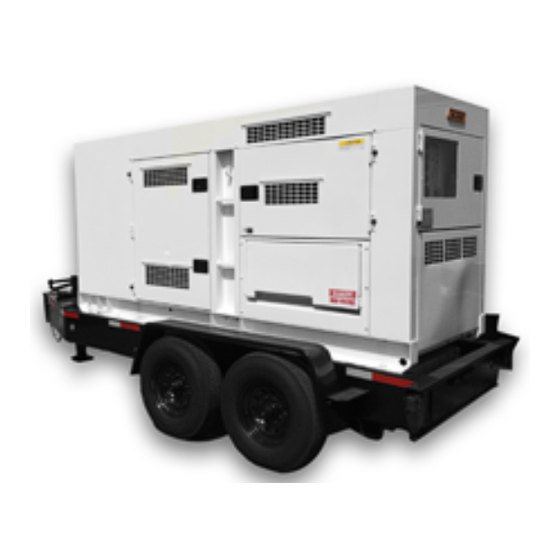
Generator the art " Open-Delta " excitation system. The open delta The MQ Power Model DCA-150SSVU is a 96 kW generator system consist of an electrically independent winding wound (Figure 4) that is designed as a high quality portable (requires among stationary windings of the AC output section. - Page 22 DCA150SSVU — MAJOR COMPONENTS Figure 4. Major Components t a r r o j f f u r e l y l b y l b o l c y l b r o t y l b y l b y l b e t t y l b...
- Page 23 DCA-150SSVU — GENERATOR CONTROL PANEL Figure 5. Generator Control Panel Located behind the generator control panel is the Generator The definitions below describe the controls and functions of Control Box . This box contains some of the necessary the DCA-150SSVU " Generator Control Panel " (Figure 5). electronic components required to make the genertator Main Circuit Breaker –...
- Page 24 NOTE PAGE DCA-150SSVU— OPERATION AND PARTS MANUAL (STD)— REV. #1 (06/03/03) — PAGE 25...
- Page 25 DCA-150SSVU — ENGINE OPERATING PANEL Figure 7. Engine Operating Panel PAGE 26 — DCA-150SSVU— OPERATION AND PARTS MANUAL (STD) — REV. #1 (06/03/03)
- Page 26 DCA-150SSVU — ENGINE OPERATING PANEL The definitions below describe the controls and functions of During cranking cycle , The MPEC will attempt to crankthe the DCA-150SSVU " Engine Operating Panel " (Figure 7). engine for 10 seconds before disengaging. If the engine does not engage (start) by the third attempt, the engine will be Panel Light –...
- Page 27 DCA-150SSVU — OUTPUT TERMINAL PANEL FAMILIARIZATION Output Terminal Panel Output Terminal Familiarization The Output Terminal Panel ( Figure 8) shown below is The “ Output Terminal Panel ” (Figure 8) is provided with located on the right-hand side (left from control panel) of the the following: generator.
- Page 28 DCA-150SSVU — OUTPUT TERMINAL PANEL FAMILIARIZATION 120 VAC GFCI Receptacles Each auxiliary receptacle is protected by a 50 amp circuit breaker. These breakers are located directly above the GFCI There are two 120 VAC, 20 amp GFCI (Duplex Nema 5-20R) receptacles.
- Page 29 DCA-150SSVU — OUTPUT TERMINAL PANEL FAMILIARIZATION Over Current Relay Connecting Loads An over current relay (Figure 14) is connected to the main Loads can be connected to the generator by the UVWO terminal circuit breaker. In the event of an overload, both the circuit lugs or the convienience receptacles.
-
Page 30: Load Application
DCA-150SSVU — LOAD APPLICATION Single Phase Load Three Phase Load When calculating the power requirements for 3-phase power Always be sure to check the nameplate on the generator use the following equation: and equipment to insure the wattage, amperage and frequency requirements are satisfactorily supplied by the generator for operating the equipment. - Page 31 DCA-150SSVU — GENERATOR OUTPUTS Generator Output Voltages Generator Amperage A wide range of voltages are available to supply voltage for Tables 7 and 8 describe the generator’s current output capa- many different applications. Voltages are selected by using bility for both 1Ø-phase and 3Ø phase applications. the voltage selector switch (Figure 15).
-
Page 32: Gauge Reading
DCA-150SSVU — GENERATOR OUTPUTS/GAUGE READING GFCI Receptacle Load Capability The load capability of the GFCI receptacles is directly re- lated to the voltage being supplied at either the UVWO ter- Use this position for minals or the 3 twist lock auxilliary receptacles. 3Ø, 208V/1Ø,120V Tables 9 and 10 show what amount of current is available at the GFCI receptacles when the UVWO terminals and twist... -
Page 33: Output Terminal Panel Connections
DCA-150SSVU — OUTPUT TERMINAL PANEL CONNECTIONS UVWO Terminal Output Voltages 3Ø 208V/1Ø120V UVWO Terminal Output Voltages Various output voltages can be obtained using the UVWO 1. Place the voltage selector switch in the 3Ø 240/139 output terminal lugs. The voltages at the terminals are de- position as shown in Figure 24. - Page 34 DCA-150SSVU — OUTPUT TERMINAL PANEL CONNECTIONS 3Ø 480/277 UVWO Terminal Output Voltages 1Ø 240V/120V UVWO Terminal Output Voltages 1. Place the voltage selector switch in the 3Ø 480/277 1. Place the voltage selector switch in the 1Ø 240/120 position as shown in Figure 27. position as shown in Figure 30.
- Page 35 DCA-150SSVU — PRE-SETUP Fuel Check Circuit Breakers To protect the generator from an overload, a 3-pole, 110 amp, DANGER: DANGER: DANGER: DANGER: DANGER: main circuit breaker is provided to protect the UVW output Fuel spillage on a hot! engine can cause terminals from overload.
- Page 36 DCA-150SSVU — PRE-SETUP CAUTION: CAUTION: CAUTION: CAUTION: CAUTION: ALWAYS! fill trailer tank first with #2 diesel fuel , before filling secondary internal tank. Figure 35. Skid Type Fuel Tank System Refueling Procedure: DANGER: DANGER: DANGER: DANGER: DANGER: Diesel fuel and its vapors are dangerous to your health and the surrounding environment.
- Page 37 DCA-150SSVU — PRE-SETUP NEVER overfill trailer fuel tank – It is important to Figure 40 below reflects a full fuel system. read the trailer fuel gauge when filling trailer fuel tank. DO NOT wait for fuel to rise in filler neck. See Figure 38. Figure 38.
- Page 38 DCA-150SSVU — PRE-SETUP Coolant (Ethylane Glycol [Green] / Water — 50/50 mix) Use only drinkable tap water. If hard water or water with When the antifreeze is mixed with NOTE many impurities is used, the inside of the engine and radiator water, the antifreeze mixing ratio may become coated with deposits and cooling efficiency must be less than 50%.
- Page 39 DCA-150SSVU — PRE-SETUP Battery When connecting battery do the following: This unit is of negative ground DO NOT connect in reverse. 1. NEVER connect the battery cables to the battery Always maintain battery fluid level between the specified terminals when the ignition switch is in either the Pre- marks.
-
Page 40: Generator Start-Up Procedure (Manual)
DCA-150SSVU — GENERATOR START-UP PROCEDURE (MANUAL) WARNING: WARNING: WARNING: WARNING: WARNING: The engine's exhaust contains harmful emissions. ALWAYS have adequate ventilation when operating . Direct exhaust away from nearby personnel. Before Starting Generator and Control Panel CAUTION: NEVER! manually start the engine with the Figure 45. - Page 41 DCA-150SSVU — GENERATOR START-UP PROCEDURE (MANUAL) 10. The generator's frequency meter (Figure 53) displays 6. Set engine speed switch to “LOW ” (Figure 49). the 60 cycle output frequency in HERTZ. Figure 49. Engine Speed Switch (Low) 7. Place the Auto-Off/Reset-Manual switch in the Figure 53.
- Page 42 DCA-150SSVU — GENERATOR START-UP PROCEDURE (MANUAL) 14. The engine oil pressure gauge (Figure 57) will indicate 17. Turn the main , GFCI , and aux . circuit breakers to the the oil pressure (kg/ cm ) of the engine. Under normal “ON”...
-
Page 43: Generator Start-Up Procedure (Auto Mode)
DCA-150SSVU — GENERATOR START-UP PROCEDURE (AUTO MODE) DANGER: Before connecting this CAUTION: generator to any building’s electrical The Engine Speed Switch must be set system, a licensed to the “HIGH” position when running in the electrician must install Auto-Start mode. Failing to set the switch an isolation (transfer) in the proper position can result in damage switch . -
Page 44: Generator Shut-Down Procedure
DCA-150SSVU — GENERATOR SHUT-DOWN PROCEDURE Shutdown Procedure - Engine Controller Emergency Shutdown Procedure - Engine Controller To shutdown the generator use the following procedure: 1. To shut-down the engine in the event of an emergency, switch the MAIN , GFCI and LOAD 1. -
Page 45: Maintenance
DCA-150SSVU — MAINTENANCE e t t t l e i t i r o f r o f s t r e t l l i F r e t o t t , t i i s t e t l r o t i t c i t c... - Page 46 DCA-150SSVU — MAINTENANCE Air Removal Flushing Out Radiator and Replacing Coolant If air enters the fuel injection system of a diesel engine, Open both cocks located at the crankcase side and at starting becomes impossible. After running out of fuel, or the lower part of the radiator and drain coolant.
- Page 47 DCA-150SSVU — MAINTENANCE If the generator will be used daily, the battery should normally Jacket Water Heater and Internal Battery Charger 120 VAC Input Receptacles (OPTIONAL) not require charging. If the generator will be idle (not used) for long periods of time, apply power to the battery charger This generator is equipped with two 120 VAC, 20 amp input receptacle via commercial power using an power cord of receptacles located on the output terminal panel.
-
Page 48: Trailer Brakes Maintenance
DCA-150SSVU — TRAILER BRAKES MAINTENANCE Brakes Hydraulic Surge Brakes Trailer brakes should be inspected the first 200 miles of Hydraulic surge brakes (Figure 67) should not require any operation. This will allow the brake shoes and drums to seat special attention with the exception of routine maintenance properly. - Page 49 DCA-150SSVU — TRAILER MAINTENANCE Suspension Tires/Wheels/Lug Nuts The leaf suspension springs and associated components Tires and wheels are a very impor tant and critical (Figure 68) should be visually inspected every 6,000 miles components of the trailer. When specifying or replacing the for signs of excessive wear, elongation of bolt holes, and trailer wheels it is important the wheels, tires, and axle are loosening of fasteners.
- Page 50 DCA-150SSVU — TRAILER MAINTENANCE Lug Nut Torque Requirements It is extremely important to apply and maintain proper wheel mounting torque on the trailer. Be sure to use only the fasteners matched to the cone angle of the wheel. Proper procedure for attachment of the wheels is as follows: 1.
- Page 51 Discount-Equipment.com is your online resource for quality parts & equipment. Florida: 561-964-4949 Outside Florida TOLL FREE: 877-690-3101 Need parts? Click on this link: http://www.discount-equipment.com/category/5443-parts/ choose one of the options to help get the right parts and equipment you are looking for.
-
Page 52: Trailer Wiring Diagram
DCA-150SSVU — TRAILER-WIRING DIAGRAM Figure 70. Trailer/Towing Vehicle Wiring Diagram PAGE 52 — DCA-150SSVU— OPERATION AND PARTS MANUAL (STD) — REV. #1 (06/03/03) -
Page 53: Generator Wiring Diagram
DCA-150SSVU — GENERATOR WIRING DIAGRAM Figure 71. Generator Wiring Diagram Figure 69. Engine Wiring Diagram DCA-150SSVU— OPERATION AND PARTS MANUAL (STD)— REV. #1 (06/03/03) — PAGE 53... - Page 54 DCA-150SSVU — ENGINE WIRING DIAGRAM (WITH CONTROLLER) Figure 72. Engine Wiring Diagram (Controller) PAGE 54 — DCA-150SSVU— OPERATION AND PARTS MANUAL (STD) — REV. #1 (06/03/03)
- Page 55 NOTE PAGE DCA-150SSVU— OPERATION AND PARTS MANUAL (STD)— REV. #1 (06/03/03) — PAGE 55...
- Page 56 DCA-150SSVU — TROUBLESHOOTING (ENGINE) Practically all breakdowns can be prevented by proper diagnosis based on the Engine Troubleshooting (Table 19). If handling and maintenance inspections, but in the event of a the problem cannot be remedied, consult our company's breakdown, use the tables shown for business office or service plant.
- Page 57 DCA-150SSVU — TROUBLESHOOTING (ENGINE) l i f r e t o l c t r i r i A e l c i t c . t u i n i i t c f l a i t c c a l i t u l .
- Page 58 DCA-150SSVU — TROUBLESHOOTING (GENERATOR) Practically all breakdowns can be prevented by proper handling and maintenance inspections, but in the event of a breakdown, use the tables shown for diagnosis based on the Engine and Radiator Troubleshooting (Table 20) . If the problem cannot be remedied, consult our company's business office or service plant.
- Page 59 DCA-150SSVU — TROUBLESHOOTING (ENGINE CONTROLLER) i t u l i o l l i F l i o v e l . l e l i O t i n i a f r u l l i o . t i l i o g i l y a l...
-
Page 60: Explanation Of Code In Remarks Column
EXPLANATION OF CODE IN REMARKS COLUMN How to read the marks and remarks used in this parts book. Items Found In the “Remarks” Column Serial Numbers-Where indicated, this indicates a serial number range (inclusive) where a particular part is used. Model Number-Where indicated, this shows that the corresponding part is utilized only with this specific model number or model number variant. -
Page 61: Suggested Spare Parts
DCA-150SSVU — SUGGESTED SPARE PARTS DCA-150SSVU W/VOLVO TAD720GE DIESEL ENGINE 1 TO 3 UNITS Qty. Description 1 ..0601820671.....AUTOMATIC VOLTAGE REGULATOR 1 ..47530102 ......KNOB, SELECTOR SWITCH 1 ..0601840073.....RHEOSTAT, VOLTAGE REGULATOR 1 ..0601840121.....KNOB, RHEOSTAT 3 ..978515 ......V-BELT, ALTERNATOR 3 .. -
Page 62: Name Plate And Decals
DCA-150SSVU — NAMEPLATE AND DECALS NAME PLATE ASSY. PAGE 62 — DCA-150SSVU— OPERATION AND PARTS MANUAL (STD) — REV. #1 (06/03/03) - Page 63 DCA-150SSVU — NAMEPLATE AND DECALS NAME PLATE ASSY. PART NO. PART NAME QTY. REMARKS M3552000403 DECAL, OPERATING PROCEDURES ........1 ..... M35200040 M9520100304 DECAL, SAFETY INSTRUCTIONS ..........1 ..... M92010030 M9520100603 DECAL, CAUTION ...............2 ..... M92010060 CONTROL PANEL, BOX & OPERATING PANEL GROUP M3550001303 DECAL, CONTROL PANEL ............
- Page 64 DCA-150SSVU — NAMEPLATE AND DECALS (CONT.) NAME PLATE ASSY. (CONT.) PAGE 64 — DCA-150SSVU— OPERATION AND PARTS MANUAL (STD) — REV. #1 (06/03/03)
- Page 65 DCA-150SSVU — NAMEPLATE AND DECALS (CONT.) NAME PLATE ASSY. (CONT.) PART NO. PART NAME QTY. REMARKS BONNET GROUP M9510200002 DECAL, MQ ..................1 ..... M91020000 0600500090 EMBLEM 0021106015 MACHINE SCREW M3560100903 STRIPE M3560101003 STRIPE M3560101604 STRIPE M3560101304 STRIPE M3560101203 STRIPE M3560101403 STRIPE M3560101504 STRIPE...
- Page 66 DCA-150SSVU — GENERATOR ASSY. GENERATOR ASSY. PAGE 66 — DCA-150SSVU— OPERATION AND PARTS MANUAL (STD) — REV. #1 (06/03/03)
- Page 67 DCA-150SSVU — GENERATOR ASSY. GENERATOR ASSY. PART NO. PART NAME QTY. REMARKS C0110000402 ROTOR ASSEMBLY ........1 ..INCLUDES ITEM W/ FIELD ASSEMBLY 8131070013 B131611014 COUPLING DISK 8131015003 BALANCING PLATE ........1 ..PURCHASE 1-14 AS A SET 0012112035 HEX. HEAD BOLT 0042612000 SPRING WASHER 8101026013...
- Page 68 DCA-150SSVU — CONTROL BOX ASSY. CONTROL BOX ASSY. PAGE 68 — DCA-150SSVU— OPERATION AND PARTS MANUAL (STD) — REV. #1 (06/03/03)
- Page 69 DCA-150SSVU — CONTROL BOX ASSY. CONTROL BOX ASSY. PART NO. PART NAME QTY. REMARKS M3213000502 CONTROL BOX 0601808821 CIRCUIT BREAKER ........1 ..LAF364001039 3P 400A 0021006080 MACHINE SCREW 0601823863 RELAY UNIT ..........2 ..MSA9013A 0027104016 MACHINE SCREW 0601820671 AUTOMATIC VOLTAGE REGULATOR ..
- Page 70 DCA-150SSVU — CONTROL BOX ASSY. (CONT.) CONTROL BOX ASSY. (CONT.) PAGE 70 — DCA-150SSVU— OPERATION AND PARTS MANUAL (STD) — REV. #1 (06/03/03)
- Page 71 DCA-150SSVU — CONTROL BOX ASSY. (CONT.) CONTROL BOX ASSY. (CONT.) PART NO. PART NAME QTY. REMARKS LY2DUS12VDC RELAY ............1 ..REPLACES 0601827656 PTF08A RELAY BASE ..........1 ..REPLACES 0601823109 PYCA1 RELAY CLIP ..........2 ..REPLACES 0601824400 LY2DUS12DVC RELAY ............
- Page 72 DCA-150SSVU — ENGINE AND RADIATOR ASSY. ENGINE & RADIATOR ASSY. PAGE 72 — DCA-150SSVU— OPERATION AND PARTS MANUAL (STD) — REV. #1 (06/03/03)
- Page 73 DCA-150SSVU — ENGINE AND RADIATOR ASSY. ENGINE & RADIATOR ASSY. PART NO. PART NAME QTY. REMARKS M3923200034 ENGINE & RADIATOR SET ...... 1 ..VOLVO TAD720GE V20405830 ELEMENT, AIR CLEANER ......1 ..REPLACES 0602046621 V3831236 CARTRIDGE, OIL FILTER ......1 ..REPLACES 0602041277 V3825133 CARTRIDGE, FUEL FILTER .....
- Page 74 DCA-150SSVU — ENGINE AND RADIATOR ASSY. (CONT.) ENGINE & RADIATOR ASSY. (CONT.) PAGE 74 — DCA-150SSVU— OPERATION AND PARTS MANUAL (STD) — REV. #1 (06/03/03)
- Page 75 DCA-150SSVU — ENGINE AND RADIATOR ASSY. (CONT.) ENGINE & RADIATOR ASSY. (CONT.) PART NO. PART NAME QTY. REMARKS V20412362 RADIATOR V20412281 CAP, RADIATOR V20417379 UPPER WATER PIPE V20405972 UPPER HOSE RADIATOR V20405956 LOWER HOSE RADIATOR V20412342 LOWER WATER PIPE V20412341 LOWER WATER PIPE GASKET V947281 BOLT...
- Page 76 DCA-150SSVU — ENGINE OPERATING PANEL ASSY. ENGINE OPERATING PANEL ASSY. PAGE 76 — DCA-150SSVU— OPERATION AND PARTS MANUAL (STD) — REV. #1 (06/03/03)
- Page 77 DCA-150SSVU — ENGINE OPERATING PANEL ASSY. ENGINE OPERATING PANEL ASSY. PART NO. PART NAME QTY. REMARKS ECU9988N150V CONTROLLER, ECU ..........1 ..REPLACES 0602202545 0601831340 SWITCH ..............1 ..7562K4 0601831395 ENGINE SPEED SWITCH ........1 ..7302K36 0602120096 TACHOMETER ............1 ..111812 0602122097 OIL PRESSURE GAUGE ........
- Page 78 DCA-150SSVU — OUTPUT TERMINAL PANEL ASSY. DCA-150 SSVU — OUTPUT TERMINAL ASSY. OUTPUT TERMINAL ASSY. PAGE 78 — DCA-150SSVU— OPERATION AND PARTS MANUAL (STD) — REV. #1 (06/03/03)
- Page 79 DCA-150SSVU — OUTPUT TERMINAL PANEL ASSY. DCA-150 SSVU — OUTPUT TERMINAL ASSY. OUTPUT TERMINAL ASSY. PART NO. PART NAME QTY. REMARKS M3230700003 TERMINAL PANEL M9220100304 OUTPUT TERMINAL BOLT M9220100404 TIE BOLT 0039316000 HEX. NUT 0040016000 SPRING WASHER 0041416000 PLAIN WASHER 0016908035 HEX.
- Page 80 DCA-150SSVU — BATTERY ASSY. BATTERY ASSY. PAGE 80 — DCA-150SSVU— OPERATION AND PARTS MANUAL (STD) — REV. #1 (06/03/03)
- Page 81 DCA-150SSVU — BATTERY ASSY. BATTERY ASSY. PART NO. PART NAME QTY. REMARKS 0602220196 BATTERY M9310500404 BATTERY SHEET M9103000504 BATTERY BAND 0602220921 BATTERY BOLT SET 0040006000 SPRING WASHER M3346900704 BATTERY CABLE M3346900604 BATTERY CABLE CABLE ............1 ..MAKE LOCALLY 0017112025 HEX.
- Page 82 DCA-150SSVU — MUFFLER ASSY. MUFFLER ASSY. PAGE 82 — DCA-150SSVU— OPERATION AND PARTS MANUAL (STD) — REV. #1 (06/03/03)
- Page 83 DCA-150SSVU — MUFFLER ASSY. MUFFLER ASSY. PART NO. PART NAME QTY. REMARKS M3330100302 MUFFLER 0016910025 HEX. HEAD BOLT M3333000603 EXHAUST PIPE V20405969 GASKET ........... 1 ..REPLACES 0602320197 M3333200104 GASKET 0017110030 HEX. HEAD BOLT 0017110050 HEX. HEAD BOLT M3330400804 COVER M3330400903 BRACKET 0016908020...
- Page 84 DCA-150SSVU — FUEL TANK ASSY. FUEL TANK ASSY. PAGE 84 — DCA-150SSVU— OPERATION AND PARTS MANUAL (STD) — REV. #1 (06/03/03)
- Page 85 DCA-150SSVU — FUEL TANK ASSY. FUEL TANK ASSY. PART NO. PART NAME QTY. REMARKS M3363000902 FUEL TANK 0605505070 CAP, FUEL TANK M3363200204 TANK BAND M9310500104 SUPPORTER SHEET 0016908020 HEX. HEAD BOLT 0207308000 HEX. NUT 0222100660 RUBBER SHEET M9200000003 DRAIN JOINT M9200200004 DRAIN BOLT 0150000018...
- Page 86 DCA-150SSVU — ENCLOSURE ASSY. ENCLOSURE ASSY. ADD THE FOLLOWING DIGITS AFTER THE PART NUMBER WHEN ORDERING ANY PAINTED PANEL TO INDICATE COLOR OF UNIT: 5 -BLACK 1-ORANGE 6 -CATERPILLAR YELLOW 2-WHITE 7 -CATO GOLD 3 -SPECTRUM GRAY 8 -RED 4 -SUNBELT GREEN THE SERIAL NUMBER MAY BE REQUIRED.
- Page 87 DCA-150SSVU — ENCLOSURE ASSY. ENCLOSURE ASSY. PART NO. PART NAME QTY. REMARKS M3413001502 BASE M141340004 UNDER COVER 0016904020 HEX. HEAD BOLT M3423000902 FRONT FROME M3493104913 ACOUSTIC SHEET 0016910025 HEX. HEAD BOLT M3423200304 COVER, FRONT FRAME M3493103104 ACOUSTIC SHEET 0016908020 HEX. HEAD BOLT M3433000602 CENTER FRAME M3493200304...
- Page 88 DCA-150SSVU — ENCLOSURE ASSY. (CONT.) ENCLOSURE ASSY. (CONT.) ADD THE FOLLOWING DIGITS AFTER THE PART NUMBER WHEN ORDERING ANY PAINTED PANEL TO INDICATE COLOR OF UNIT: 5 -BLACK 1-ORANGE 6 -CATERPILLAR YELLOW 2-WHITE 7 -CATO GOLD 3 -SPECTRUM GRAY 8 -RED 4 -SUNBELT GREEN THE SERIAL NUMBER MAY BE REQUIRED.
- Page 89 DCA-150SSVU — ENCLOSURE ASSY. (CONT.) ENCLOSURE ASSY. (CONT.) PART NO. PART NAME QTY. REMARKS M3493405514 ACOUSTIC SHEET 0016908055 HEX. HEAD BOLT 0016910025 HEX. HEAD BOLT M3453002203 SIDE DOOR M3493416704 ACOUSTIC SHEET M3453002303 SIDE DOOR M3493414404 ACOUSTIC SHEET M3453000903 SIDE DOOR M3493405204 ACOUSTIC SHEET M3453001413...
- Page 90 DCA-150SSVU — RUBBER SEALS ASSY. RUBBER SEALS ASSY. PAGE 90 — DCA-150SSVU— OPERATION AND PARTS MANUAL (STD) — REV. #1 (06/03/03)
- Page 91 DCA-150SSVU — RUBBER SEALS ASSY. RUBBER SEALS ASSY. PART NO. PART NAME QTY. REMARKS 0228901075 SEAL RUBBER 0229200930 SEAL RUBBER 0228901120 SEAL RUBBER 0228901090 SEAL RUBBER 0228900955 SEAL RUBBER 0228900520 SEAL RUBBER 0229201200 SEAL RUBBER 0229201140 SEAL RUBBER 0228800680 SEAL RUBBER 0228801070 SEAL RUBBER 0228800640...
- Page 92 Discount-Equipment.com is your online resource for quality parts & equipment. Florida: 561-964-4949 Outside Florida TOLL FREE: 877-690-3101 Need parts? Click on this link: http://www.discount-equipment.com/category/5443-parts/ choose one of the options to help get the right parts and equipment you are looking for.
Need help?
Do you have a question about the WHISPERWATT DCA-150SSVU and is the answer not in the manual?
Questions and answers