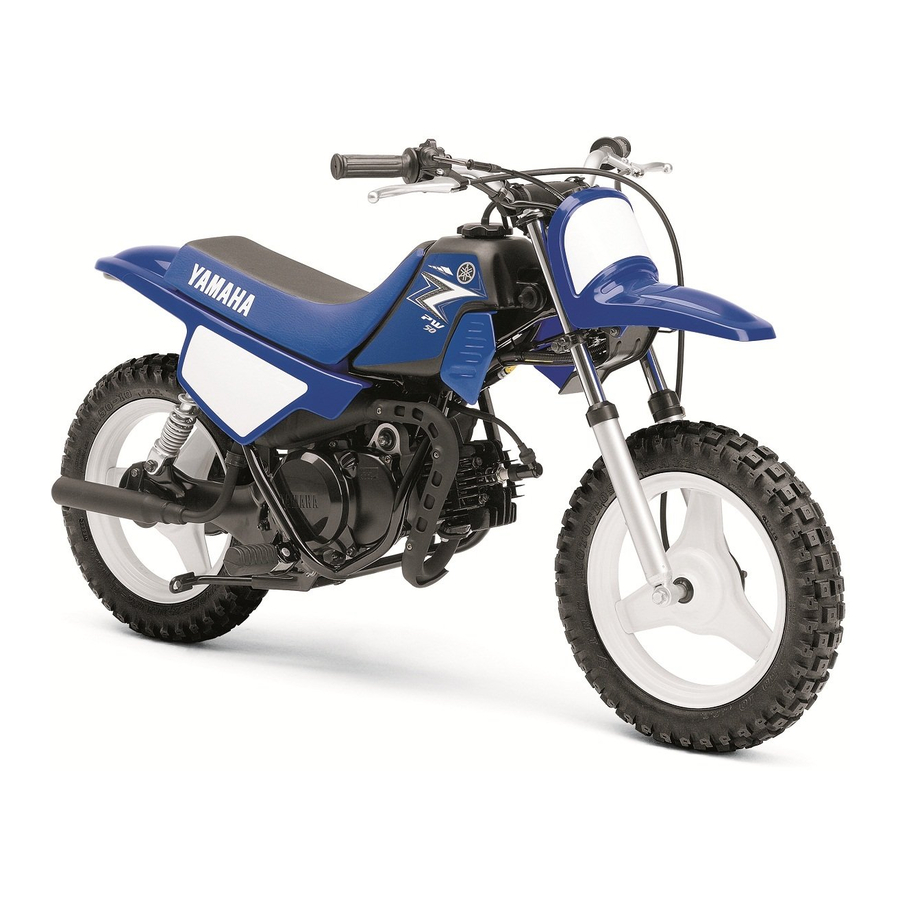
Yamaha PW50 Owner's Manual
Hide thumbs
Also See for PW50:
- Owner's manual (80 pages) ,
- Owner's manual (82 pages) ,
- Owner's manual (164 pages)
Table of Contents
Advertisement
Read this manual carefully before operating this vehicle.
Il convient de lire attentivement ce manuel avant la pre-
mière utilisation du véhicule.
Bitte lesen Sie diese Bedienungsanleitung sorgfältig
durch, bevor Sie das Fahrzeug in Betrieb nehmen.
MANUEL DU PROPRIÉTAIRE
BEDIENUNGSANLEITUNG
OWNER'S MANUAL
PW50
PW50D
PW50D1
5PG-28199-8B
Advertisement
Table of Contents
Troubleshooting

Related Manuals for Yamaha PW50


Summary of Contents for Yamaha PW50
- Page 1 Read this manual carefully before operating this vehicle. Il convient de lire attentivement ce manuel avant la pre- mière utilisation du véhicule. Bitte lesen Sie diese Bedienungsanleitung sorgfältig durch, bevor Sie das Fahrzeug in Betrieb nehmen. OWNER’S MANUAL MANUEL DU PROPRIÉTAIRE BEDIENUNGSANLEITUNG PW50 PW50D PW50D1 5PG-28199-8B...
- Page 2 PRINTED ON RECYCLED PAPER PRINTED IN JAPAN IMPRIMÉ SUR PAPIER RECYCLÉ 2012.07-0.6×1 CR AUF RECYCLINGPAPIER GEDRUCKT (E,F,G)
- Page 3 Read this manual carefully before operating this vehicle. OWNER’S MANUAL PW50 PW50D PW50D1 5PG-28199-8B-E0...
- Page 4 Read this manual carefully before operating this vehicle. This manual should stay with this vehicle if it is sold. EC Declaration of Conformity conforming to Directive 2006/42/EC We, YAMAHA MOTOR CO., LTD. 2500 Shingai, Iwata, Japan, declare in sole responsibility, that the product PW50 (JYA3PT00000428377–...
- Page 5 Yamaha has met these standards without reducing the performance or economy of operation of the motorcycle. To maintain these high standards, it is important that you and your Yamaha dealer pay close attention to the recommended maintenance schedules and operating instructions contained within this manual.
- Page 6 Your motorcycle is equipped with an adjustable speed limiter and a power reduction plate. Yamaha recommends that all be- ginners start off with the speed limiter adjusting screw turned in and the power reduction plate installed in the exhaust man- ifold to limit the power available while they learn.
-
Page 7: Important Manual Information
IMPORTANT MANUAL INFORMATION EAU10133 Particularly important information is distinguished in this manual by the following notations: This is the safety alert symbol. It is used to alert you to potential personal injury hazards. Obey all safety messages that follow this symbol to avoid possible injury or death. - Page 8 IMPORTANT MANUAL INFORMATION EAU10200 PW50/PW50D/PW50D1 OWNER’S MANUAL ©2012 by Yamaha Motor Co., Ltd. 1st edition, June 2012 All rights reserved. Any reprinting or unauthorized use without the written permission of Yamaha Motor Co., Ltd. is expressly prohibited. Printed in Japan.
-
Page 9: Table Of Contents
TABLE OF CONTENTS LOCATION OF IMPORTANT FOR YOUR SAFETY – Checking the throttle grip free LABELS ..........1-1 PRE-OPERATION CHECKS ..... 5-1 play ........... 7-12 Tires ..........7-12 SAFETY INFORMATION ....2-1 OPERATION AND IMPORTANT Panel wheels ........ 7-14 RIDING POINTS ........ 6-1 Adjusting the front and DESCRIPTION ........3-1 Starting and warming up... - Page 10 TABLE OF CONTENTS SPECIFICATIONS ......9-1 CONSUMER INFORMATION...10-1 Identification numbers ....10-1...
-
Page 11: Location Of Important Labels
Read and understand all of the labels on your vehicle. They contain important information for safe and proper operation of your vehicle. Never remove any labels from your vehicle. If a label becomes difficult to read or comes off, a replacement label is available from your Yamaha dealer. For Canada... - Page 12 LOCATION OF IMPORTANT LABELS For Canada WARNING • BEFORE YOU OPERATE THIS VEHICLE, READ THE OWNER’S MANUAL AND ALL LABELS. • NEVER CARRY A PASSENGER. You increase your risk of losing control if you carry a passenger. • NEVER OPERATE THIS VEHICLE ON PUBLIC ROADS. You can collide with another vehicle if you operate this vehicle on a public road.
- Page 13 LOCATION OF IMPORTANT LABELS For Canada TIRE INFORMATION INFORMATION SUR LES PNEUS Cold tire nor mal pressure should be set as La pression des pneus à froid doit normalement follows. être réglée comme suit. FRO NT : 1 0 0 k Pa , { 1. 00 k g f / c m ² }, 15 p si AVANT : 1 0 0 k Pa, { 1 .0 0 k g f/cm²...
- Page 14 LOCATION OF IMPORTANT LABELS For Europe...
- Page 15 LOCATION OF IMPORTANT LABELS For Europe PW50 2.1 kW 39 kg 5PG-2156A-10 5B6-2816R-00 EN16029 2012 YAMAHA MOTOR CO., LTD. 100 kPa 100 kPa 2500 SHINGAI, IWATA, JAPAN 1.00 kgf/cm² 1.00 kgf/cm² 15 psi 15 psi 5B6-2817L-00 5PG-2816R-00...
- Page 16 LOCATION OF IMPORTANT LABELS Familiarize yourself with the following pictograms and read the explanatory text. Read the Owner’s manual. Never use on paved roads. Always approved Never carry passengers. helmet and protective gear. Use from 6 years old. This unit contains high- Operation of this motorcycle...
- Page 17 LOCATION OF IMPORTANT LABELS Use unleaded gasoline only. 1 Year of construction **** YAMAHA MOTOR CO., LTD. 2500 SHINGAI, IWATA, JAPAN Measure the tire pressure when the tires are cold. Adjust the tire pressure. Improper tire pressure can cause loss of control.
- Page 18 LOCATION OF IMPORTANT LABELS For Oceania and South Africa...
- Page 19 LOCATION OF IMPORTANT LABELS For Oceania and South Africa WARNING TIRE INFORMATION • BEFORE YOU OPERATE THIS VEHICLE, READ THE OWNER’S Cold tire nor mal pressure should be set as MANUAL AND ALL LABELS. follows. • NEVER CARRY A PASSENGER. You increase your risk of losing control if you carry a passenger.
-
Page 20: Safety Information
SAFETY INFORMATION ● ● EAU4093B Never operate a motorcycle with- The failure of motorists to detect out proper training or instruction. and recognize motorcycles in traf- Take a training course. Beginners fic is the predominating cause of Be a Responsible Owner should receive training from a cer- automobile/motorcycle accidents. - Page 21 SAFETY INFORMATION ● ● Many accidents involve inexperi- the handlebar and both feet on the Always wear protective clothing enced operators. operator footrests during operation that covers your legs, ankles, and • Make sure that you are qualified to maintain control of the motorcy- feet.
- Page 22 Yamaha accessories, which are avail- idly reach dangerous levels. as possible. Securely pack your able only from a Yamaha dealer, have ● Do not run engine in poorly venti- heaviest items as close to the cen-...
- Page 23 SAFETY INFORMATION ucts or having other modifications per- • Bulky or large accessories may appropriate. Refer to page 7-12 for tire formed to your vehicle that change any seriously affect the stability of specifications and more information on of the vehicle’s design or operation the motorcycle.
- Page 24 SAFETY INFORMATION cation for the straps carefully so the straps will not rub against painted surfaces during transport. ● The suspension should be com- pressed somewhat by the tie- downs, if possible, so that the mo- torcycle will not bounce excessive- ly during transport.
-
Page 25: Description
DESCRIPTION EAU10410 Left view 1. Spark plug (page 7-6) 2. Fuel cock (page 4-6) 3. Throttle stop screw (page 7-11) 4. Air filter element (page 7-9) 5. Kickstarter (page 4-7) 6. Centerstand (page 7-17) -
Page 26: Right View
DESCRIPTION EAU10420 Right view 1. Spark arrester (page 7-10) 2. Seat (page 4-7) 3. Transmission oil filler cap (page 7-8) 4. 2-stroke engine oil tank (page 4-6) 5. Transmission oil drain bolt (page 7-8) -
Page 27: Controls And Instruments
DESCRIPTION EAU10430 Controls and instruments 1. Rear brake lever (page 4-3) 2. Starter (choke) lever (page 4-7) 3. 2-stroke engine oil tank cap (page 4-6) 4. Engine stop switch (page 4-1) 5. Front brake lever (page 4-2) 6. Throttle grip (page 7-12) 7. -
Page 28: Instrument And Control Functions
INSTRUMENT AND CONTROL FUNCTIONS ● EAU40660 The engine speed is limited while EAU41044 Handlebar switch Speed limiter and power re- this switch is set to the “START” duction plate position, therefore the motorcycle Your motorcycle is equipped with an cannot be ridden in that switch po- adjustable speed limiter and a power sition. -
Page 29: Front Brake Lever
INSTRUMENT AND CONTROL FUNCTIONS the throttle grip can only be opened ap- EAU12901 Front brake lever proximately halfway. If more power is required, please consult a Yamaha dealer. EWA14631 WARNING Improper adjustment of the speed limiter could cause improper throttle operation. -
Page 30: Rear Brake Lever
INSTRUMENT AND CONTROL FUNCTIONS EAU12951 EAU13182 EAU13212 Rear brake lever Fuel tank cap Fuel Make sure there is sufficient gasoline in the tank. EWA10881 WARNING Gasoline and gasoline vapors are extremely flammable. To avoid fires and explosions and to reduce the risk of injury when refueling, follow these instructions. - Page 31 10% (E10). Gasohol containing methanol is not recom- 1. Fuel tank filler tube Recommended fuel: mended by Yamaha because it can 2. Maximum fuel level REGULAR UNLEADED GASO- cause damage to the fuel system or ve- LINE ONLY 3.
-
Page 32: Fuel Tank Breather Hose
INSTRUMENT AND CONTROL FUNCTIONS Your Yamaha engine has been de- or premium unleaded fuel. Use of un- EAU13412 Fuel tank breather hose signed to use regular unleaded gaso- leaded fuel will extend spark plug life line with a research octane number of and reduce maintenance costs. -
Page 33: 2-Stroke Engine Oil
INSTRUMENT AND CONTROL FUNCTIONS EAU13453 EAU40701 O (on) 2-stroke engine oil Fuel cock Make sure that there is sufficient 2- The fuel cock supplies fuel from the stroke engine oil in the oil tank. Add the tank to the carburetor while filtering it al- recommended 2-stroke engine oil as necessary. -
Page 34: Starter (Choke) Lever
INSTRUMENT AND CONTROL FUNCTIONS EAU13590 EAU13680 EAU40920 Starter (choke) lever “ ” Kickstarter Seat To remove the seat 1. Remove the mudguard by remov- ing the bolts and washers. 1. Starter (choke) lever “ ” 1. Kickstarter Starting a cold engine requires a richer To start the engine, fold out the kick- air-fuel mixture, which is supplied by starter lever, move it down lightly with... -
Page 35: Cable Lock (For Europe)
INSTRUMENT AND CONTROL FUNCTIONS EAU53760 4. Route one end of the cable Cable lock (for Europe) through the rear wheel, and then Your motorcycle came with an external insert both ends of the cable into anti-theft device to help prevent unau- the lock assembly and lock it. -
Page 36: For Your Safety - Pre-Operation Checks
Failure to inspect or maintain the vehicle properly increases the possibility of an accident or equipment damage. Do not operate the vehicle if you find any problem. If a problem cannot be corrected by the procedures provided in this manual, have the vehicle inspected by a Yamaha dealer. Before using this vehicle, check the following points:... - Page 37 • Make sure that operation is smooth. • Check throttle grip free play. Throttle grip 7-12, 7-16 • If necessary, have Yamaha dealer adjust throttle grip free play and lubricate cable and grip housing. • Make sure that operation is smooth. Control cables 7-16 •...
-
Page 38: Operation And Important Riding Points
1. Turn the fuel cock lever to “O” (on). there is a control or function you do not that the starter (choke) is not required 2. Set the engine stop switch to understand, ask your Yamaha dealer. when the engine is warm. Instead, start “START”. EWA10271 the engine with the throttle slightly 3. -
Page 39: Starting Off
OPERATION AND IMPORTANT RIDING POINTS EAU41002 EAU16780 EAU41012 Starting off Acceleration and deceleration Braking 1. While applying the rear brake le- EWA14571 WARNING ver, push the motorcycle off the centerstand. ● Avoid braking hard or suddenly 2. Completely close the throttle. (especially when leaning over to 3. -
Page 40: Engine Break-In
Since the engine is brand new, do not immediately have a Yamaha dealer put an excessive load on it for the first 5 check the vehicle. hours of operation. The various parts in the engine wear and polish themselves to the correct operating clearances. -
Page 41: Parking
OPERATION AND IMPORTANT RIDING POINTS EAU40722 Parking When parking, stop the engine, and then turn the fuel cock lever to “S” (stop). EWA10311 WARNING ● Since the engine and exhaust system can become very hot, park in a place where pedestri- ans or children are not likely to touch them and be burned. -
Page 42: Periodic Maintenance And Adjustment
– possibly leading to pending on the weather, terrain, geo- that is certified (if applicable). Yamaha death. See page 2-2 for more in- graphical location, and individual use, dealers are trained and equipped to... -
Page 43: Owner's Tool Kit
If you do not have the tools or experi- ence required for a particular job, have a Yamaha dealer perform it for you. -
Page 44: Periodic Maintenance Chart For The Emission Control System
PERIODIC MAINTENANCE AND ADJUSTMENT EAU41742 Periodic maintenance chart for the emission control system Items marked with an asterisk should be performed by a Yamaha dealer as they require special tools, data and technical skills. THEREAFTER INITIAL EVERY ITEM CHECK OR MAINTENANCE JOB... -
Page 45: General Maintenance And Lubrication Chart
PERIODIC MAINTENANCE AND ADJUSTMENT EAU41757 General maintenance and lubrication chart Items marked with an asterisk should be performed by a Yamaha dealer as they require special tools, data and technical skills. THEREAFTER INITIAL EVERY ITEM CHECK OR MAINTENANCE JOB month... - Page 46 Apply lithium-soap-based grease lightly. Shock absorber Check operation and for oil leakage. assemblies Replace if necessary. Apply Yamaha chain and cable lube or engine oil Control cables 10W-30 lightly. Check operation. Check throttle grip free play, and adjust if necessary.
-
Page 47: Checking The Spark Plug
If the spark plug shows a distinctly dif- ferent color, the engine could be oper- ating improperly. Do not attempt to diagnose such problems yourself. In- stead, have a Yamaha dealer check 1. Spark plug cap the vehicle. 2. Remove the spark plug as shown, with the spark plug wrench includ- ed in the owner’s tool kit. -
Page 48: Removing The Power Reduction Plate
PERIODIC MAINTENANCE AND ADJUSTMENT EAU41103 Spark plug gap: Removing the power reduc- 0.6–0.7 mm (0.024–0.028 in) tion plate To obtain full engine performance ca- To install the spark plug pability, removing the power reduction 1. Clean the surface of the spark plug plate is required. -
Page 49: Transmission Oil
In order to prevent clutch slip- for oil leakage before each ride. If any page (since the transmission oil leakage is found, have a Yamaha deal- also lubricates the clutch), do er check and repair the motorcycle. In not mix any chemical additives. -
Page 50: Middle And Final Gear Cases
If any leakage is found, have maintenance and lubrication chart. a Yamaha dealer check and repair the Clean or, if necessary, replace the air motorcycle. addition,... -
Page 51: Cleaning The Spark Arrester
2. Tap the tailpipe lightly, and then Recommended oil: Cleaning the spark arrester use a wire brush to remove any Yamaha foam air filter oil or other The spark arrester should be cleaned carbon deposits from the spark ar- quality foam air filter oil... -
Page 52: Adjusting The Carburetor
Therefore, most car- checked and, if necessary, adjusted as buretor adjustments should be left to a follows at the intervals specified in the Yamaha dealer, who has the neces- periodic maintenance and lubrication sary professional knowledge and expe- chart. -
Page 53: Checking The Throttle Grip Free Play
Operation of this vehicle with im- 2. Tire tread depth and, if necessary, have a Yamaha deal- proper tire pressure may cause se- er adjust it. vere injury or death from loss of The tires must be checked before each control. - Page 54 After extensive tests, only the tires list- excessively worn tires. Operat- ed below have been approved for this ing the motorcycle with exces- model by Yamaha Motor Co., Ltd. sively worn tires decreases riding stability and can lead to loss of control.
-
Page 55: Panel Wheels
The wheel rims should be checked for cracks, bends, warpage or Front damage before each ride. If any damage is found, have a Yamaha dealer replace the wheel. Do not 1. Front brake lever free play attempt even the smallest repair to Rear the wheel. -
Page 56: Checking The Front And Rear Brake Shoes
To remove the rear wheel: See Yamaha dealer replace the brake page 7-20. shoes as a set. If proper adjustment cannot be ob- tained as described, have a Yamaha Front dealer make this adjustment. Be sure to measure the brake lining at the thinnest portion. -
Page 57: Checking And Lubricating The Cables
The operation of all control cables and The operation of the throttle grip should which must be adjusted by a Yamaha the condition of the cables should be be checked before each ride. In addi-... -
Page 58: Lubricating The Front And Rear Brake Levers
WARNING push down hard on the handlebars If the centerstand does not move up several times to check if the front and down smoothly, have a Yamaha fork compresses and rebounds dealer check or repair it. Otherwise, smoothly. the centerstand could contact the ground and distract the operator, re- sulting in a possible loss of control. -
Page 59: Checking The Steering
Yamaha dealer check or re- tion chart. If there is play in the wheel ward and backward. If any free pair it. -
Page 60: Front Wheel
PERIODIC MAINTENANCE AND ADJUSTMENT EAU24360 EAU41032 Front wheel To install the front wheel 1. Install the brake shoe plate into the wheel hub as shown. EAU41024 To remove the front wheel EWA10821 WARNING To avoid injury, securely support the vehicle so there is no danger of it falling over. -
Page 61: Rear Wheel
PERIODIC MAINTENANCE AND ADJUSTMENT 8. Push down hard on the handlebar EAU25080 Rear wheel several times to check for proper fork operation. EAU41084 To remove the rear wheel EWA10821 WARNING To avoid injury, securely support the vehicle so there is no danger of it falling over. - Page 62 PERIODIC MAINTENANCE AND ADJUSTMENT 6. Remove the exhaust manifold bolts, and then remove the ex- haust chamber, the power reduc- tion plate and the gasket. 1. Muffler 1. Rear shock absorber mounting bolt 2. Washer 8. Remove the axle nut while apply- 3.
- Page 63 PERIODIC MAINTENANCE AND ADJUSTMENT 5. Install the right-side rear shock ab- Tightening torques: sorber by installing the mounting Exhaust manifold bolt: bolt. 9 Nm (0.9 m·kgf, 6.5 ft·lbf) Exhaust chamber bolt: 6. While applying the rear brake, 18 Nm (1.8 m·kgf, 13 ft·lbf) tighten the axle nut to the specified torque.
-
Page 64: Troubleshooting
However, should your motorcycle require any repair, take it to a Yamaha dealer, whose skilled technicians have the necessary tools, experience, and know-how to service the motorcycle properly. -
Page 65: Troubleshooting Chart
Wipe off with a dry cloth and correct the spark plug gap, or replace the spark plug. the kickstarter. Remove the spark plug and check the electrodes. The engine does not start. Have a Yamaha dealer check the vehicle. Have a Yamaha dealer check the vehicle. 7-24... -
Page 66: Motorcycle Care And Storage
Cleaning ble. Rust and corrosion can develop matte colored finished parts. Be ECA17110 sure to consult a Yamaha dealer for even if high-quality components are NOTICE advice on what products to use be- used. A rusty exhaust pipe may go un- ●... - Page 67 MOTORCYCLE CARE AND STORAGE ● Do not use any harsh chemical After riding in the rain or near the sea 5. Touch up minor paint damage products on plastic parts. Be Since sea salt is extremely corrosive, caused by stones, etc. sure to avoid using cloths or carry out the following steps after each 6.
-
Page 68: Storage
Always store your motorcycle in a cool, 3. Drain the carburetor float chamber dry place and, if necessary, protect it Consult a Yamaha dealer for advice on by loosening the drain bolt; this will against dust with a porous cover. Be what products to use. - Page 69 MOTORCYCLE CARE AND STORAGE e. Remove the spark plug cap from the spark plug, and then install the spark plug and the spark plug cap. WARNING! To prevent damage or injury from sparking, make sure to ground the spark plug elec- trodes while turning the en- gine over.
-
Page 70: Specifications
SPECIFICATIONS Dimensions: Vibration on handlebar (EN1032, ISO5008): Air filter: PW50 Will not exceed 2.5 m/s² Overall length: Air filter element: (AUT)(BEL)(CHE)(DEU)(DNK)(ESP) 1245 mm (49.0 in) Wet element (FIN)(FRA)(GBR)(GRC)(IRL)(ITA)(NLD) Overall width: Fuel: (NOR)(POL)(PRT)(SVN)(SWE) 575 mm (22.6 in) Recommended fuel: Engine: Overall height: PW50 Regular unleaded gasoline only 715 mm (28.1 in) - Page 71 Ignition system: Wheel type: 2.50-10 4PR Panel wheel Manufacturer/model: Rim size: PW50 (EUR) 10x1.50 BRIDGESTONE/KNOBBY Rear wheel: PW50 (ZAF), PW50D, PW50D1 Wheel type: BRIDGESTONE/KNOBBY Panel wheel IRC/KNOBBY Rim size: Speed rating: 10x1.50 100 km/h (62 mph) Front brake: Rear tire:...
- Page 72 SPECIFICATIONS EAU51131 For Europe only The figures quoted are emission levels and are not necessarily safe working levels. Whilst there is a correlation be- tween the emission and exposure lev- els, this cannot be used reliably to determine whether or not further pre- cautions are required.
-
Page 73: Consumer Information
Record the vehicle identification num- ber and model label information in the spaces provided below for assistance when ordering spare parts from a Yamaha dealer or for reference in case the vehicle is stolen. VEHICLE IDENTIFICATION NUMBER: 1. Vehicle identification number 1. - Page 74 CONSUMER INFORMATION EAU48120 tions related to exhaust emissions as Vehicle Emission Control Informa- required by federal law, state law and tion label (For Canada) Environment Canada. 1. Vehicle Emission Control Information label 1. Vehicle Emission Control Information label The Vehicle Emission Control Informa- tion label is affixed at the location in the illustration.
- Page 75 INDEX Tool kit ............ 7-2 Transmission oil........7-8 Acceleration and deceleration ....6-2 Identification numbers ......10-1 Troubleshooting ........7-23 Air filter element, cleaning ...... 7-9 Troubleshooting chart ......7-24 Autolube pump, adjusting ..... 7-16 Kickstarter ..........4-7 Vehicle Emission Control Information Brake lever, front ........
- Page 76 EAU53771 WARNING Improper motorcycle use can result in SEVERE INJURY or DEATH. ALWAYS USE NEVER USE NEVER CARRY PASSENGERS AN APPROVED ON PAVED HELMET AND ROADS PROTECTIVE GEAR NEVER ALWAYS operate: • without proper training or instruction. • use proper riding techniques to avoid •...
Need help?
Do you have a question about the PW50 and is the answer not in the manual?
Questions and answers