Table of Contents
Advertisement
Advertisement
Table of Contents

Summary of Contents for Proficient Audio Systems M40
- Page 1 Audio Systems 80W x 2 Channel Stereo Receiver Installation & User Guide...
-
Page 2: Important Safety Instructions
IMPORTANT SAFETY INSTRUCTIONS APPLICABLE FOR USA, CANADA OR WHERE APPROVED FOR USAGE CAUTION: To reduce the risk of electric CAUTION: TO PREVENT ELECTRIC SHOCK, shock, do not remove cover (or back). MATCH WIDE BLADE PLUG TO WIDE SLOT, No user-serviceable parts inside. Refer INSERT FULLY. -
Page 3: Table Of Contents
AC Outlets Connections ......................................24 AC Power Cord ..........................................24 FRONT PANEL CONNECTIONS .......................................24 Video 3 Front Panel Connections .....................................24 Headphones Connection ......................................24 OPERATING THE M40 ................................25 Install M40 Remote Batteries ......................................25 Turning ON the M40 .........................................25 Selecting Speakers A/B ........................................25 Volume ..............................................26 Mute ................................................26... -
Page 4: Introduction
The M40 also features a Front Panel Headphone Jack for private listening plus, a Sleep Timer has been built in to the M40, to automatically shut the M40 OFF for those late night sessions when the M40 could keep run- ning long after you have drifted off to sleep. -
Page 5: What's Included
M40 FEATURES WHAT’S INCLUDED 1 – M40 80W x 2 Channel Stereo Receiver 1 – M40 IR Remote Control 2 – AAA Batteries 1 – FM Indoor Antenna SP. A 1 – AM Loop Antenna 1 – M40 Installation & User Guide... -
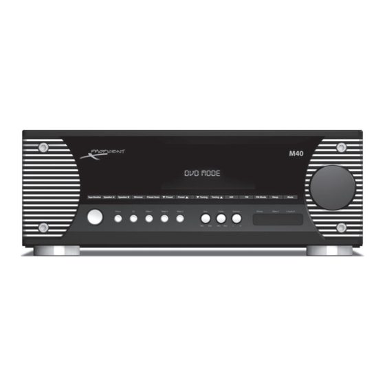
Page 6: Front Panel
1. ON/STANDBY - Press this button to turn the M40 ON/OFF. In Standby, the button is surrounded by a red backlight to indicate that the M40 main power is ON. To turn the unit ON, press the button. The backlight turns blue and the Front Panel Display illuminates. - Page 7 Front Panel Display to the right of the tuned frequency. 15. AM and FM - In Standby or with the M40 power ON, press this button to turn the M40 ON, (if OFF) and select the AM Tuner. The tuner will select the last tuned AM Channel.
- Page 8 Pre-Out Jacks. 19. VOLUME - With the M40 ON turn this knob to adjust the speaker level audio output. Turn clockwise to turn volume up; turn counterclockwise to turn the volume down. The audio output level in dB (decibels) will be displayed on the Front Panel Dis-...
-
Page 9: Rear Panel
23. CD IN - (2 RCA Jacks) Connect to the left and right line level audio outputs of a CD Player or other device such as a MP3 Player, Music Server, etc. CD IN is selected by pressing the CD button on either the M40 Front Panel or Remote Control. When select- ed, the Front Panel Display will indicate CD. - Page 10 26. VID 2 IN - (3 RCA Jacks) Connect to the left and right line level audio and composite video outputs of a DVD Player, Satellite Receiver, Cable Box or other audio/video device. VID 2 In is selected by pressing the VIDEO 2 button on the M40 Front Panel or the VID 2 button on the Remote Control.
- Page 11 M40 amplifier as an additional room in the system. 36. SPEAKER A - Connect the Left + and Left – Speaker A five way binding posts on the M40 to the main room Left + and Left –...
-
Page 12: M40 Remote Features
47. AUTO PRESET - With the FM Band selected, press this button automatically program the Preset Channels with the first 30 tun- able FM channels found. The M40 can store up to 30 Presets. If fewer than 30 FM channels are found the M40 will cycle the FM Band a second time to try to find more channels. - Page 13 Sub Out B associated with Speaker B. 59. AM - In Standby or with the M40 power ON, press this button to turn the M40 ON, (if OFF) and select the AM Band. The tuner will select the last tuned AM Channel.
-
Page 14: Installation
Providing proper ven- tilation for good air flow will help keep the temperature down and protect not only the M40 but all system components and help preserve their longevity. -
Page 15: Speaker Placement
INSTALLATION Video Display Front Front Left Right A=B=C Ideal Listening Zone Diagram 5 Speaker Placement SPEAKER PLACEMENT Use the following recommendations when determining speaker placement. Determine The Ideal Listening Zone The area where the user will most likely be sitting when listening to the speakers is the Ideal Listening Zone. Placement of Stereo Speakers The distance between the left and right speakers should equal the distance from one speaker to the listener as closely as pos- sible. -
Page 16: Connections
Note: Do not connect more than one pair of 4Ω speakers directly to the M40. Do not connect more than one pair of 8Ω speakers directly to the Speaker A and B Terminals at the same time. This will cause the M40 to shut down and can damage the unit. This type of damage is not covered by the Warranty. -
Page 17: Speaker B
Note: Do not connect more than one pair of 4Ω speakers directly to the M40. Do not connect more than one pair of 8Ω speakers directly to the Speaker A and B Terminals at the same time. This will cause the M40 to shut down and can damage the unit. This type of damage is not covered by the Warranty. -
Page 18: Multiple Pair Speaker Hookup For A Multiroom Sound System
WARNING: Never connect more than one pair of 8Ω speakers directly to the Speaker A and Speaker B Terminals at the same time. Doing so can damage the M40. This type of damage is not covered by the Warranty. Always use an impedance matching device such as the Proficient VC60i Volume Control (one for each speaker pair) to protect the M40 from overload. - Page 19 All four pair should be connected to the Speaker A Terminal as shown in Diagram 8. Setting Impedance The M40 is capable of handling a 4Ω load. For 4Ω amp configuration using Proficient VC60i Impedance Matching Volume Controls, use Chart 1. If using another impedance matching device follow the manufacturer’s instructions for that device.
- Page 20 12. For regular use, set the room volume controls to full ON. Adjust the M40 to a good listening level. Leave the M40 volume con- trol in that setting and adjust volume with the individual room volume controls.
-
Page 21: Rear Panel Connections
REAR PANEL CONNECTIONS Antenna Connections Connect the AM and FM Antennas to the AM and FM Antenna Terminals on the M40 Rear Panel as shown in Diagram 9. AM Antenna 1. Connect the included AM Loop Antenna to the Antenna AM &... -
Page 22: Tape In/Out Connections
AUDIO RECORDER Connect a CDR, Tape Deck or other audio record/playback device to Tape In/Out on the M40 Rear Panel as shown in Diagram 12. The Tape In/Out can also be used as a loop connection for an audio signal processor. -
Page 23: Video 3 Rear Panel Connections
(Diagram 16) Add additional Flashers as needed. 3. If using source components that feature IR Control Inputs, using a mono mini-mini cable connect the Remote OUT on the M40 Rear Panel to the IR Remote IN Jack on the device being controlled. -
Page 24: Ac Outlets Connections
Connect a Video Game, MP3 Player, still or video camera, or other audio/video device that is not a regular system compo- nent to the VID 3 A/V Inputs on the M40 Front Panel as shown in Diagram 19 Video 3 Front Panel Connections Diagram 19. -
Page 25: Operating The M40
OPERATING THE M40 OPERATING THE M40 Before operating the M40, be sure all instructions from the previous sections have been followed regarding installation and connections. Install M40 Remote Batteries M40 Remote Rear The M40 Remote Control comes with two AAA batteries. Install them into the Battery Compartment as shown in Diagram 21. -
Page 26: Volume
Mute With the M40 power ON and with any source selected, press the Mute button on the M40 Front Panel or Remote to cut the amplifier output to the selected speakers. (There will be no sound coming from the speakers.) MUTE will slowly flash on the Front Panel Display. -
Page 27: Selecting A Source
Diagram 28. If the channel is FM Stereo, the STEREO icon will appear. If the channel is a Preset, the Preset Number will be displayed. If the M40 is in Standby a press of one of these buttons will turn the M40 ON and select the Tuner Band. -
Page 28: Presets
Presets The M40 can store up to 30 AM or FM Preset Channels (30 total). They can be stored manually by individually tuning channels and saving them as Presets. The Auto Preset function can be used to quickly store up to 30 FM channels. Auto Preset will scan the FM Band up to two times and then stop automatically. -
Page 29: Dimmer
With the M40 ON and with any source selected, press the Sleep SP. A button on the M40 Front Panel or M40 Remote to turn on the M40 Sleep Timer. Sleep Timer durations from 90-10 minutes in 10 minute increments can be set. -
Page 30: Tape Monitor (Audio Recording)
5. With the M40 in Standby, press and hold the M40 Front Panel Preset Scan and Mute buttons until the Firmware version ap- pears on the Front Panel Display. Release the buttons. The display will flash a few times and turn off. The M40 will restore to Standby. -
Page 31: Troubleshooting
Unit does not power up a) Confirm Power Cord is plugged in to an unswitched 110V AC Outlet. ON/Standby button Backlight does not illuminate b) Confirm Main Power Switch on M40 Rear Panel is in the ON position. Audio No Sound From Speakers a) Confirm source audio connections. -
Page 32: Specifications
SPECIFICATIONS Audio Sections Power Output/Channel (RMS, two channels driven into 8Ω) 80 Watts, 20Hz to 20kHz THD (at rated power) <0.007% Power/Channel (RMS, 2 channels driven into 4Ω) 125 Watts <0.1% @ 1kHz Damping Factor > 100 Input Sensitivity (For rated power @ max VC) 220 mV Line IN, 2.0mV Phono IN Input Impedance (Source Inputs) 11 K Ohms Line IN, >20 k Ohms Phono IN... - Page 33 SPECIFICATIONS Control Sections Trigger Outputs (0 to 14V DC) 14V @ 10 mA, 9.0V @100mA General Power Consumption 120V Version Standby 3.0 Watts No signal (idle) 55 Watts At 1/8 Rated Power (10 Watts/Channel, 8Ω) 180 Watts At 1/8 of 125 Watts (15.6 Watts/Channel, 4Ω) 260 Watts Rear Panel marked Line Ratings 120V AC, 60 Hz, 230 Watts...
-
Page 34: Limited 2-Year Warranty
Proficient will bear the cost of returning the repaired or replaced product to you, freight prepaid. All replaced parts and product become the property of Proficient Audio Systems. The foregoing is your sole and exclusive remedy for breach of warranty. If the product is not found to be defective, Proficient will contact you to arrange for return of the product to you, at your expense. - Page 35 NOTES...
- Page 36 Audio Systems 940 Columbia Avenue, Riverside, CA 92507 877.888.9004 • Fax 951.750.6304 • proficientaudio.com ©2008 Proficient Audio Systems 1300-72400 (rev2)
Need help?
Do you have a question about the M40 and is the answer not in the manual?
Questions and answers