American Dynamics ControlCenter ADCC0200 Installation And Operation Instructions Manual
American dynamics keyboard installation and operation instructions
Hide thumbs
Also See for ControlCenter ADCC0200:
- Quick reference manual (4 pages) ,
- Specifications (15 pages) ,
- Quick reference manual (4 pages)

Related Manuals for American Dynamics ControlCenter ADCC0200


Summary of Contents for American Dynamics ControlCenter ADCC0200
- Page 1 ControlCenter ADCC0200 ADCC0300 Keyboard Installation and Operation Instructions 8200-0855-05 A0...
-
Page 2: Important Information
When unpacking your new Tyco Video product, check for missing or damaged items. If When unpacking your new American Dynamics product, check for missing or damaged items. If any item is missing, or if damage is evident, DO NOT INSTALL OR OPERATE THIS PRODUCT any item is missing, or if damage is evident, DO NOT INSTALL OR OPERATE THIS PRODUCT. - Page 3 TO REDUCE RISK OF ELECTRIC SHOCK, DO NOT REMOVE COVER. NO USER SERVICEABLE PARTS INSIDE. REFER SERVICING TO QUALIFIED SERVICE PERSONNEL. TO PREVENT FIRE OR SHOCK HAZARD, DO NOT EXPOSE THIS APPLIANCE TO RAIN OR MOISTURE. DO NOT INSTALL THIS PRODUCT IN HAZARDOUS AREAS WHERE HIGHLY COMBUSTIBLE OR EXPLOSIVE PRODUCTS ARE STORED OR USED.
- Page 4 PPOUR RÉDUIRE LES RISQUES D’ÉLECTROCUTION, NE PAS DÉPOSER LE COUVERCLE. AUCUN COMPOSANT NE PEUT ÊTRE RÉPARÉ PAR L’UTILISATEUR. FAIRE APPEL À UN TECHNICIEN DE MAINTENANCE COMPÉTENT. POUR PRÉVENIR TOUT RISQUE D’INCENDIE OU D’ÉLECTROCUTION, NE PAS EXPOSER CETTE UNITÉ À LA PLUIE NI À L’HUMIDITÉ. NE PAS INSTALLER CET APPAREIL DANS UN ENDROIT DANGEREUX OÙ...
- Page 5 UM STROMSCHLÄGE ZU VERMEIDEN, DARF DIE ABDECKUNG NICHT ENTFERNT WERDEN. DAS GERÄT ENTHÄLT KEINE DURCH DEN ANWENDER WARTBAREN TEILE. WARTUNGSARBEITEN DÜRFEN NUR VON QUALIFIZIERTEM WARTUNGSPERSONAL DURCHGEFÜHRT WERDEN. DIESES GERÄT DARF KEINER FEUCHTIGKEIT ODER REGEN AUSGESETZT WERDEN. DIESES PRODUKT DARF NICHT IN GEFAHRENBEREICHEN INSTALLIERT WERDEN, IN DENEN LEICHT ENTFLAMMBARE ODER EXPLOSIVE PRODUKTE GELAGERT ODER VERWENDET WERDEN.
- Page 6 PER RIDURRE IL RISCHIO DI SHOCK ELETTRICI, NON RIMUOVERE IL COPERCHIO. L’INTERNO NON CONTIENE PARTI CHE L’UTENTE POSSA RIPARARE. RIVOLGERSI A TECNICI DI ASSISTENZA QUALIFICATI. PER EVITARE IL RISCHIO DI INCENDI O SHOCK, NON ESPORRE L’APPARECCHIO ALLA PIOGGIA O ALL’UMIDITÀ. NON INSTALLARE IL PRODOTTO IN AREE A RISCHIO, NELLE QUALI SONO IMMAGAZZINATI O UTILIZZATI MATERIALI ALTAMENTE INFIAMMABILI O ESPLOSIVI.
- Page 7 CON EL FIN DE REDUCIR EL RIESGO DE DESCARGA ELÉCTRICA, ABSTÉNGASE DE RETIRAR LA CUBIERTA, YA QUE EN SU INTERIOR NO HAY NINGÚN COMPONENTE QUE PUEDA SER REPARADO POR EL USUARIO. EN EL CASO DE QUE SEA NECESARIO, ACUDA A PERSONAL DE SERVICIO CUALIFICADO PARA QUE REALICE LA REPARACIÓN.
- Page 8 OM DE KANS OP ELEKTRISCHE SCHOKKEN TE VERMIJDEN, DIENT U DE KAP NIET TE VERWIJDEREN. HET APPARAAT BEVAT GEEN ONDERDELEN DIE DOOR DE GEBRUIKER KUNNEN WORDEN GEREPAREERD. LAAT ONDERHOUD UITVOEREN DOOR GEKWALIFICEERD ONDERHOUDSPERSONEEL. OM DE KANS OP BRAND OF ELEKTRISCHE SCHOKKEN TE VERMIJDEN, DIENT U DIT APPARAAT NIET AAN REGEN OF VOCHT BLOOT TE STELLEN.
-
Page 9: Table Of Contents
CHAPTER 1: ABOUT THE ADCC0200 AND ADCC0300 KEYBOARD ... 3 Key Features ... 3 ADCC0200 and ADCC0300 Keyboard Overview ... 4 Feature Quick Reference ... 7 CHAPTER 2: CONNECTION AND SETUP ... 11 Ancillary Equipment ... 11 MP-KMI Keyboard Matrix Interface ... 11 Installation Precautions ... - Page 10 CHAPTER 4: PROGRAMMING WITH THE ADCC0200/ADCC0300 KEYBOARDS ... 28 Entering Program Mode (RS232 only) ... 28 Exiting Program Mode (RS232 only) ... 28 Matrix Menu ... 29 Dome Menu Functions ... 30 Navigating Dome Camera Menus ... 30 Setting Presets ... 31 Programming Dome Patterns ...
-
Page 11: Chapter 1: About The Adcc0200 And Adcc0300 Keyboard
Key Features The ADCC0200/ADCC0300 is a video control station that is fully compatible with the American Dynamics MegaPower family of matrix switchers. The ADCC0200/ADCC0300 enables the user to view and control cameras and video recorders at local and remote facilities, and to control auxiliary devices such as door locks and lights. Additionally, the operator can acknowledge alarms with the unit. -
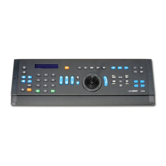
Page 12: Adcc0200 And Adcc0300 Keyboard Overview
ADCC0200 and ADCC0300 Keyboard Overview The keyboard consists of the following elements: 1. Clear key - clears any numerical data entered during camera, monitor selection etc. Used to backstep or exit the menu system. 2. Menu key - used to enter the matrix menu system. 3. - Page 13 11. Numeric keypad - keys ranging from 0 to 9 that enable the user to select specific cameras, monitors, presets, sequences, etc. 12. Monitor key - selects the monitor whose number was entered on the numeric keypad. 13. Camera key - selects the camera whose number was entered on the numeric keypad.
- Page 14 ADCC0200 and ADCC0300 33. Auxiliary key - toggles auxiliary between ON state and OFF state (if function is available). 34. Flip key - automatically turns the selected dome through 180 35. Auxiliary 2 key - toggles auxiliary 2 between ON state and OFF state. 36.
-
Page 15: Feature Quick Reference
Feature Quick Reference The features that are available depend on the keyboard in use (ADCC0200 or ADCC0300) and the communication format that is utilized (RS232 or RS485). Standard Matrix Operations FEATURE KEYBOARD COMMAND Monitor number → Select Monitor Camera number → Select Camera Site number →... - Page 16 ADCC0200 and ADCC0300 Standard Matrix Operations (continued) FEATURE KEYBOARD COMMAND Tour number → Run Tour Hold Tour Restart Current Tour Last and Next Camera (When Tour Held) Function number → F1 Function Function number → F2 Function Matrix Menu Operations FEATURE KEYBOARD COMMAND Enter Menu Mode...
- Page 17 Dome Operations FEATURE KEYBOARD COMMAND Enter Dome Menu Mode Exit Dome Menu Mode Via Dome Menu Scroll Up Dome Menu Joystick Up Scroll Down Dome Menu Joystick Down Scroll Left in Dome Menu Joystick Left Scroll Right in Dome Menu Joystick Right Cycle Field Options/Values Enter Selection...
- Page 18 ADCC0200 and ADCC0300 VCR (PIP) / Direct Control Mode (All Functions Available in Direct Control Mode) FEATURE KEYBOARD COMMAND RS232: VCR number → Select VCR Mode RS485: Play Stop Rewind Fast Forward Record Pause Reverse Play Search Menu Enter ENTER key Increment/Decrement Record or Playback Speed Joystick Up...
-
Page 19: Chapter 2: Connection And Setup
Chapter 2: Connection and Setup This chapter describes the power and data connections between the ADCC0200/ ADCC0300 keyboard and the switching system being used. IMPORTANT NOTE The default setting for the keyboard is RS485 mode at 19200 baud. To change these settings, enter the Special Config menu by pressing SHIFT ( within five seconds of powering up the keyboard. -
Page 20: Installation Precautions
Installation Precautions This installation should only be carried out by qualified personnel, and should conform to all local electrical codes. Safeguards should be taken to avoid unintentional operation by employees and maintenance personnel working about the premises, by falling objects, by customers, by building vibration, and by similar causes. -
Page 21: Connections For Cable Distance Of Seven Feet Or Less (Rs232 Mode)
Keyboard Installation and Operation Connections for Cable Distance of Seven Feet or Less (RS232 Mode) For installations where the keyboard-to-system cable distance is seven feet or less, connect the cables in accordance with the figures below. The RJ-45 socket on the MP-KMI that is marked Matrix is connected to the switching system. -
Page 22: Multiple Keyboards On An Rs485 Network
Multiple Keyboards on an RS485 Network A maximum of 16 devices may be connected when working in RS485 mode. A maximum of eight keyboards can be assigned to the system. For correct connection of multiple keyboards to an MegaPower LT, please see the MegaPower LT Installation and Operation Handbook. -
Page 23: Multiple Keyboards On An Rs232 Network
Multiple Keyboards on an RS232 Network Use the following diagram as guidance to connect multiple RS232 keyboards via a port expander. The following rules must be observed: A maximum of four RS232 keyboards can be connected to the network. The distance between two system components should not exceed 50 feet/15 meters. -
Page 24: Chapter 3: Basic Operations - Operate Mode (Adcc0200 And Adcc0300)
ADCC0200 and ADCC0300 Chapter 3: Basic Operations - Operate Mode (ADCC0200 and ADCC0300) This chapter describes basic keyboard operations such as calling cameras to view on monitors, running tours, patterns, presets, macros and salvos. It also explains menu navigation and camera functions such as how to pan, tilt and zoom cameras, and how to control lens functions. -
Page 25: Keyboard Display
Keyboard Display The 16 character, two-line LCD keyboard display shows site, monitor, and camera numbers, as well as various status messages and numerical data entered by the user. The main functional areas of the LCD display are shown below. Note: when running a tour, information about the current camera is shown on the monitor displaying the tour. -
Page 26: Controlling A Camera's Pan, Tilt And Zoom
ADCC0200 and ADCC0300 S01 M013 C0000 The selected video input will now appear on the monitor screen. After calling a camera to the selected monitor, any other camera can be called to the monitor by repeating the two steps above. Controlling a Camera’s Pan, Tilt and Zoom Once an appropriately equipped camera has been called to view on a monitor, the operator can manually control the camera's movement. -
Page 27: Controlling Camera Focus
Controlling Camera Focus Focus refers to the action of adjusting the clarity of the camera image displayed on the monitor. To focus the camera on a distant object, press the FAR key. To focus on a closer object, press the NEAR key. Controlling the Camera Iris Normally, the brightness of a picture is controlled by the camera's auto iris or other feature. -
Page 28: Auto Focus
ADCC0200 and ADCC0300 Auto Focus Certain cameras are designed with Auto Focus capability. The feature can be enabled from the keyboard as follows. To enable auto focus: 1. Hold down the FUNCTION ( 2. Press either the FOCUS NEAR/FOCUS FAR or OPEN IRIS/CLOSE IRIS keys. Auto-focus operation AND auto-iris operation is enabled. -
Page 29: Running Patterns
Running Patterns A pattern is a series of pan, tilt, zoom, and focus commands defined for a dome camera. A pattern is programmed in real time, which means that the dome remembers each pattern segment in the actual time it takes the operator to execute a command. To run a pattern: 1. -
Page 30: Running Tours
Running Tours A tour is a dynamic sequence of camera views, each of which appears on a selected monitor screen for a specified dwell time , and each of which can have a pre-programmed preset status, auxiliary status, and connect next status. Tours are also referred to as universal tours . -
Page 31: Reversing A Tour
Reversing a Tour When a tour is running, the NEXT ( direction of a tour. To reverse the direction of a tour: 1. Press the LAST ( ) key once. Stopping a Tour A running system or scratch-pad tour can be stopped by calling a camera to be displayed on the selected monitor. -
Page 32: Calling Views (Rs485 Only)
Calling Views (RS485 only) A view is the simultaneous display of a specific preset position on a specific camera. To call a view: 1. Enter the view number using the numeric keys. The number entered will appear on the right hand side of the top line of the LCD display. 2. -
Page 33: Setting The Keyboard Display Contrast
Setting the Keyboard Display Contrast 1. Press the FUNCTION ( 2. Use the Focus NEAR/Focus FAR key to increase/decrease the display's contrast. 3. When the contrast is satisfactory, press the ENTER key. Enabling or Disabling the Keyboard Sounder In the default (factory) setting mode, the keyboard's sounder sounds each time a key is pressed. -
Page 34: Operating A Vcr Or Digital Recorder
ADCC0200 and ADCC0300 Operating a VCR or Digital Recorder To initiate VCR control, the operator performs the following actions: 1. Enter the number of the VCR/DVR using the numeric keys. 2. Press the VCR SELECT ( The VCR/DVR number will be shown in the top line of the display in the format R nnnn. The keyboard's VCR keys can now be used to control the selected VCR/DVR. -
Page 35: Telemetry Enable/Disable (Rs485 Only)
Telemetry Enable/Disable (RS485 only) To send telemetry commands to cameras, it is necessary to enable telemetry to the selected camera. The telemetry key has a toggle action. To enable/disable telemetry: 1. Press the TELEMETRY ( Note it is not necessary to enable telemetry in order to use the joystick to control the movement of a camera. -
Page 36: Chapter 4: Programming With The Adcc0200/Adcc0300 Keyboards
ADCC0200 and ADCC0300 Chapter 4: Programming with the ADCC0200/ADCC0300 Keyboards This chapter provides step-by-step instructions for programming the keyboard. Programming operations require the entry of the Program Lock passcode. IMPORTANT NOTE In RS232 mode, the ADCC0300 keyboard has programming functionality and is able to set presets, access matrix menus and dome configuration menus. -
Page 37: Matrix Menu
SHIFT key + CLEAR ( previously displayed screen Several American Dynamics switching systems provide menu programming for a variety of functions. Camera groups, system tours, system salvos, alarm contact tables, monitor arming, and event timers are among the variables that may be defined through menu programming. -
Page 38: Dome Menu Functions
ADCC0200 and ADCC0300 Dome Menu Functions The ADCC0300 keyboard can be used to configure a suitable dome camera by remotely accessing the dome camera's menu system To enter the dome camera menu: 1. Call the dome camera to the monitor. 2. -
Page 39: Setting Presets
To exit a dome camera menu: 1. Use the joystick to select QUIT WITHOUT SAVING - this will exit the dome menu without saving any changes. 2. Use the joystick to select EXIT AND SAVE CHANGES - this will save any changes and exit the dome menu. -
Page 40: Clearing Patterns
ADCC0200 and ADCC0300 Clearing Patterns (RS485 only) If a dome supports the clear pattern feature, then this operation will delete the programmed pattern. To clear a pattern: 1. Press the FUNCTION ( 2. Enter the pattern number using the numeric keys. 3. -
Page 41: Chapter 5: Installer Functions
Chapter 5: Installer Functions This chapter provides step-by-step instructions for keyboard installer functions. Installer operations are accessed using the Special Configuration menu. Entering the Special Configuration Menu During the first five seconds after the unit is powered up, the display shows the current software version number, the selected baud rate, etc. -
Page 42: Setting The Network Timeout Period
ADCC0200 and ADCC0300 Setting the Network Timeout Period 1. Enter the Special Config menu. 2. Press the VCR SELECT ( 3. At the "RS485 Timeout" prompt, enter the period required. The number entered is in units of 5mS e.g. entering 10 will set the timeout period to 50mS. 4. -
Page 43: Disabling/Enabling The Sounder
Disabling/Enabling the Sounder 1. Enter the Special Config menu. 2. Press the VCR FAST FORWARD ( 3. At the "Sound 1=On 2=Off" prompt, enter 1, or 2 and then press the ENTER key. Selecting RS485 or RS232 mode 1. Enter the Special Config menu. 2. -
Page 44: Setting The Passcode (Program Lock) Function
ADCC0200 and ADCC0300 Setting the Passcode (Program Lock) Function IMPORTANT - to set the passcode, the keyboard must be in RS232 mode. 1. Enter the Special Config menu. 2. Press the MENU ( 3. At the "Program Keylock Enter to Enable" prompt, press the ENTER key. 4. -
Page 45: Appendix A: Adcc0200/Adcc0300 Vcr Reprogramming
Appendix A: ADCC0200/ADCC0300 VCR Reprogramming The ability to reprogram the RS232 commands, that are sent out when the unit is in RS485 mode with Direct Control enabled, has been added. The default commands are those applicable to the Direct Control and are shown in the second and third columns below: Label In order to reprogram these commands, the SEARCH (... - Page 46 ADCC0200 and ADCC0300 The following text should initially be shown on the teminal: PLA 02 46 50 4C 03 REV 02 52 50 4C 03 PAU 02 50 41 55 03 REW 02 52 45 57 03 FWD 02 46 57 44 03 REC 02 52 45 43 03 STP 02 53 54 4F 03 DZM 02 53 45 41 03...
-
Page 47: Appendix B: Monitor Arming Commands
Appendix B: Monitor Arming Commands Monitors are armed for alarm call up with codes that specify the following three parameters: 1. The display method ( single , dual , or block monitors). 2. The queuing method ( sequence or hold ). 3. -
Page 48: Appendix C: Troubleshooting
ADCC0200 and ADCC0300 Appendix C: Troubleshooting Problem ✗ No power to keyboard ✗ No response to keystrokes (power verified) ✗ Keyboard responds to keystrokes on some, but not all keys ✗ Cannot perform menu programming (ADCC0300 only) ✗ Display not visible ✗... -
Page 49: Appendix D: Specifications
Appendix D: Specifications Model Numbers ADCC0200 ... Keyboard with two-axis joystick ADCC0300 ... Keyboard with three-axis joystick MP-CBL ... Spare cable MP-KMI ... Keyboard Matrix Interface ADCCACPSN ... US Remote Keyboard Kit ADCCACPSP ... EU/UK Remote Keyboard Kit Size ... 16 x 2 white text on black background, user adjustable Controls Keys ... -
Page 50: Index
Index Alarms 24 Auto Focus 20 Auto Iris 19 Auto Repeat Mode 35 Auxiliaries 24 Baud Rate 34 Biasing the Network 14 Calling a Camera to View on a Monitor 17 Calling Presets (Shots) 20 Calling Salvos 23 Calling Views 24 Camera Flip 19 Camera Focus 19 Camera Iris 19... - Page 51 Function Tables DirectSet Feature 10 Dome Operations 9 Matrix Menu Operations 8 Standard Matrix Operations 7 VCP (PIP) / Direct Control Mode 10 Holding Tours 22 Keyboard Address 33 Audible Warning 25 Display 17 Display Contrast 25 Retries 33 Sounder 35 Keyboard Matrix Interface 11 Keys 4 LCD 17...
- Page 52 Program Mode Entering 28 Exiting 28 Locking 28 Setting the Passcode 36 Programming Dome Patterns 31 Resetting to Factory Defaults 35 Restarting a Held Tour 22 Reversing Tours 23 RS485 and RS232 Modes 35 Running Patterns 21 Running Tours 22 Salvos 23 Selecting Monitors 17 Setting Presets 31...
- Page 53 Keyboard Installation and Operation...
- Page 54 ADCC0200 and ADCC0300...
- Page 55 Keyboard Installation and Operation...
- Page 56 ADCC0200 and ADCC0300 Please visit our website for more information www.americandynamics.net © 2006 American Dynamics Product specifications subject to change without notice Certain product names mentioned herein may be trade names 8200-0855-05 A0 MP200-300HB-7 and/or registered trademarks of other companies...
Need help?
Do you have a question about the ControlCenter ADCC0200 and is the answer not in the manual?
Questions and answers