Table of Contents
Advertisement
Quick Links
- 1 Front of Vehicle
- 2 Checking Operation of Power Supply
- 3 Operating and Maintenance Instructions
- 4 Raising Antenna to Operating Position
- 5 Rotating Antenna for Best Picture
- 6 What to Do When Your Rv/Tv Antenna Is Not Working Properly
- 7 How Your System Works
- 8 Ordering Repair Parts
- Download this manual
OWNER'S MANUAL/INSTALLATION INSTRUCTIONS
WINEGARD RV ANTENNA
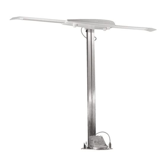
STEP 1: Choose location for antenna that will allow it to rest in travel position
with antenna pointing toward rear of vehicle and raise and rotate without
interfering with other roof-mounted equipment. Make sure inside ceiling
area is clear where ceiling plate will mount.
NOTE: Figure 1 shows minimum distance mount should be located
from edge of vehicle roof. We recommend you check with your dealer
or the manufacturer to see what provisions have been made in the
roof for mounting the antenna. A reinforced area in the roof as well as
pre-wired downlead may be available. For sloped/round roofs, use
Winegard Model RW-1000, roof wedge, to level installation.
STEP 2: Locate template and drill 1-3/4" hole through roof and ceiling of
vehicle. Take care to avoid damage to wiring which may run between roof
and ceiling.
STEP 3: Drill 1/2" hole for cable entry through roof of vehicle only. DO NOT
DRILL THROUGH CEILING. Route downlead cable through ceiling and
wall to power supply location.
STEP 4: The mount is designed to fit roofs from 1" to 4-3/4" thick. As
supplied, the mount will fit a roof 4-3/4" thick. If roof is less than 4-3/4" thick,
cut elevating shaft and directional handle to size, per table below. If roof is
more than 4-3/4" thick (max. 6"), a directional handle extension is needed.
Order Model EK-1036, Directional Handle Extension.
* * * * *
The handle and extension should be glued together after checking that
you have the correct length . The handle will not work properly if it is not
glued together! (PVC glue is recommended; for your safety, use according
to manufacturer's directions.)
ROOF
THICKNESS
6"
5 3/4"
5 1/2"
5 1/4"
5"
4 3/4"
4 1/2"
4 1/4"
4"
3 3/4"
3 1/2"
3 1/4"
3"
2 3/4"
2 1/2"
2 1/4"
2"
1 3/4"
1 1/2"
1 1/4"
1" min.
All Sensar
MADE IN U.S.A.
ELEVATING SHAFT
W/RW-1000
LENGTH
7 3/8"
7 7/8"
7 1/8"
7 5/8"
6 7/8"
7 3/8"
6 5/8"
7 1/8"
6 3/8"
6 7/8"
6 1/8"
6 5/8"
5 7/8"
6 3/8"
5 5/8"
6 1/8
5 3/8"
5 7/8"
5 1/8"
5 5/8"
4 7/8"
5 3/8"
4 5/8"
5 1/8"
4 3/8"
4 7/8"
4 1/8"
4 5/8"
3 7/8"
4 3/8"
3 5/8"
4 1/8"
3 3/8"
3 7/8"
3 1/8"
3 5/8"
2 7/8"
3 3/8"
2 5/8"
3 1/8"
2 3/8"
2 7/8"
®
®
Models
Directional
Handle
NOTE: MEASURE FROM THE
BOTTOM OF RECESS ON
TOP OF HANDLE
DIRECTIONAL
HANDLE LENGTH
5 15/16"
5 11/16"
5 7/16"
5 3/16"
4 15/16"
4 11/16"
4 7/16"
4 3/16"
3 15/16"
3 11/16"
3 7/16"
3 3/16"
2 15/16"
2 11/16"
2 7/16"
2 3/16"
1 15/16"
1 11/16"
1 7/16"
1 3/16"
15/16"
1
10" Minimum
Distance
FIGURE 1
* * * * *
2 1/4"
EK-1036
Extension
HANDLE
EXTENSION
LENGTH
LENGTH
3 11/16"
2 1/4"
3 7/16"
2 1/4"
3 3/16"
2 1/4"
2 15/16
2 1/4"
2 11/16"
2 1/4"
2 7/16"
2 1/4"
4 7/16"
Not Used
4 3/16"
Not Used
3 15/16"
Not Used
3 11/16"
Not Used
3 7/16"
Not Used
3 3/16"
Not Used
2 15/16"
Not Used
2 11/16"
Not Used
2 7/16"
Not Used
2 3/16"
Not Used
1 15/16""
Not Used
1 11/16"
Not Used
1 7/16"
Not Used
1 3/16"
Not Used
15/16"
Not Used
Advertisement
Table of Contents

Related Manuals for Winegard sensar series


Summary of Contents for Winegard sensar series
- Page 1 A reinforced area in the roof as well as pre-wired downlead may be available. For sloped/round roofs, use Winegard Model RW-1000, roof wedge, to level installation. STEP 2: Locate template and drill 1-3/4" hole through roof and ceiling of vehicle.
- Page 2 RV-3090/4090/5090 TEMPLATE 1/2" DIA. (Template) NOTE: DO NOT DRILL THOUGH CEILING IN EXPOSED AREA. 1-3/4" DIA. DRILL COMPLETELY THROUGH CEILING TOWARD FRONT OF VEHICLE 1/8" DRILL BIT 10 HOLES. DO NOT DRILL THROUGH CEILING. MINIMUM OF 5 FT. CLEAR SPACE Rev.
- Page 3 ALL MODELS STEP 5: Attach antenna head to lift tubes with two (2) Leveling Bracket steel pins as shown in Figure 2. Align holes in leveling bracket on back of antenna head with holes in lift tubes, insert pins and secure in place with (2) E-clips. Use Antenna pliers and get a firm grip on E-clips.
- Page 4 AMPLIFIED MODELS ONLY STEP 10: Select location for wall plate. Run two coax cables (three if set 2 jack is going to be used) (RG-59 type) between locations and install connectors on each end. Mark cables so "cable input", "TV output" "Set 2"...
- Page 5 OPERATING AND MAINTENANCE INSTRUCTIONS FOR YOUR WINEGARD RV/TV ANTENNA LUBRICATION RAISING ANTENNA TO OPERATING POSITION STEP 1: To lubricate the elevating gear, apply a liberal amount of silicone spray lubricant to the elevating gear with the lift in the down position (see illustration below), then run the lift up and down a few times to distribute the lubricant over gears.
- Page 6 WHAT TO DO WHEN YOUR RV/TV ANTENNA IS NOT WORKING PROPERLY INSTALLING FC-5900 CONNECTORS ON COAX CABLE Step 1. Strip outer cover back 1/2"* from end of cable. Fray braid back as far as outer cover will allow. Step 2. Trim braid close to outer cover and remove 1/4"* of inner insulation being careful not to nick center conductor.
- Page 7 Repair parts are available at many RV dealers and/or service centers throughout the country. If you don't have a dealer/service center near you, call Winegard Company at 1-800-288-8094. Parts are available only in the packages shown here. Order by the Model No. of the package needed. Example: To order the elevating gear, order RP-3000.
- Page 8 Winegard Company warrants this Winegard product against any defects in materials or workmanship within two (2) years from date of purchase. No warranty claim will be honored unless at the time the claim is made, you present proof of purchase to an authorized Winegard dealer (if unknown, please contact Winegard Company, 3000 Kirkwood Street, Burlington, Iowa 52601-2000, telephone 319-754-0600).
Need help?
Do you have a question about the sensar series and is the answer not in the manual?
Questions and answers
how long does the shaft of the Wineguard directional handle need to be
The required shaft length for the Winegard Sensar series directional handle depends on the roof thickness. The mount fits roofs from 1" to 4-3/4" thick. If the roof is less than 4-3/4" thick, the elevating shaft and directional handle must be cut to size. If the roof is more than 4-3/4" thick (maximum 7"), a directional handle extension (Winegard Model EK-1036) is needed. When using the extension, only the directional handle should be cut, not the extension. The handle and extension must be glued together after ensuring the correct length.
This answer is automatically generated