Table of Contents
Advertisement
TRAV'LER
®
I.
a. Introduction
b. Tools required
c. Safety
d. Unpacking Unit
e. Parts list
II.
a. Roof location requirements
b. TRAV'LER mount installation
c. Cable entry plate installation
d. Cable installation
e. TRAV'LER interface box
III.
TRAV'LER notes
IV.
TRAV'LER Multi-switch Wiring Diagrams
V.
TRAV'LER quiz
Multi-Satellite HDTV Antennas
61
Advertisement
Table of Contents

Related Manuals for Winegard Trav'ler


Summary of Contents for Winegard Trav'ler
- Page 1 TRAV’LER Multi-Satellite HDTV Antennas ® Pre installation a. Introduction b. Tools required c. Safety d. Unpacking Unit e. Parts list Installation a. Roof location requirements b. TRAV’LER mount installation c. Cable entry plate installation d. Cable installation e. TRAV’LER interface box III.
-
Page 2: Tools Required
Satellite Interface Box. After completing this course, you will be able to understand the steps involved in installing and operating TRAV’LER antennas. Tools Required The tools required for Winegard TRAV’LER satellite mobile antenna installation are: Level Tape measure ... - Page 3 Safety Before beginning the installation of the satellite dish system, note these important recommendations. Install only in dry conditions. DO NOT attempt to install this system in the rain or under any wet conditions. Moisture may affect electronics and void your warranty! For best performance and to reduce signal acquisition time, park the vehicle...
- Page 4 Parts list Included with your Winegard TRAV’LER Automatic Multi-Satellite TV Antenna: Gray Coaxial Cable 30 ′ Installation/Operation Manual Black Coaxial Cable 30 ′ Mount Base TRAV’LER Interface Box Mounting Hardware Bag Reflector Cable Entry Hardware Bag ...
- Page 5 It is important to find a location on the roof that provides enough space for the TRAV’LER antenna to operate. The TRAV’LER antenna has a front and a back and must be mounted correctly to avoid damage to the antenna or to the coach. The base for the TRAV’LER unit is marked FRONT and BACK.
- Page 6 Decide where the wires will enter the vehicle. One coaxial cable per receiver and a control cable will need to be run into the vehicle. Warning : Do not run the wires through the gray area shown on this graphic: anything in the gray area will interfere with the operation of the TRAV’LER antenna and may cause damage to the object or the antenna.
-
Page 7: Cable Installation
Cable Entry Plate Installation Decide the best location for the cables to enter the vehicle. You will need to run: A coaxial directly to each receiver location. A control cable to the Internal Display unit. Drill a hole in the roof and push the required wires through. - Page 8 After completing the wiring, return to the roof. Follow the steps listed below. Apply approved sealant around the outer edge of the hole. Use the cable-entry plate and position it over the hole and cables. Use the appropriate number of screws to secure the plate to the roof.
- Page 9 TRAV’LER Interface Box ® Once the wires are run and the sealant has started to cure: Press the POWER button and hold for one second to turn the TRAV’LER interface box on. Then press ENTER and hold for two seconds or until the unit enters the menu mode. Press SELECT until the asterisk is on “Yes”...
- Page 10 Pinch Points WARNING: Pay attention to these pinch points as the antenna raises. Attach the reflector to the mounting bracket, using the nuts and bolts provided. Press POWER to stow the antenna to the travel position. Once the antenna is stowed, the power will shut off.
- Page 11 Congratulations! You have now completed installation of the Winegard TRAV’LER Satellite Antenna. Press and hold the power button for one second, and the dish will raise and begin its search routine. Once locked on the signal, the receiver may need a one time set up run. Refer to receiver manual for instructions.
- Page 12 TRAV’LER Multi-Satellite HDTV Antenna Notes 1. If a third receiver is used, connect coax C. Coax port C on the unit is disabled during the search mode. It may be easiest for most customers if they do not have the third receiver powered on until the search is completed.
-
Page 13: Additional Features
12. If the TRAV’LER antenna is up and will not come down, using the Controller, select Calibrate EL, YES, ENTER. The antenna is not broken. It has “gotten lost.” Calibrating EL will usually correct this problem. If it doesn’t, call Winegard Technical Services 1- 800-788-4417. - Page 14 CL-SK26 Control Cable Extension 25’ extension power/communication cable for TRAV’LER antennas. Connects directly to the existing TRAV’LER power/communication cable to allow for runs up to 50’. SKA-004 Roller Plate Roller plate for protecting rubber RV roof. SKA-008 Thin Roof Plate Thin roof support plate for reinforcement at TRAV’LER mounting location.
- Page 17 Note: All receivers using this switch must be DISH Pro Plus. Example: DP 311 is not compatible. DISH Pro Plus 44 Multi-Dish Switch Run Check Switch After you have connected your switch to the LNBFs and receivers in the system, you will need to run Check Switch on each receiver in your system, one at a time.
- Page 18 • For DISH Pro and DISH Pro Plus receivers, this screen should identify the installed switch as a DISH Pro Plus 44. You should see all of the satellites received by your system on the Satellite line, and the word All under the Dish Input numbers. You should also see the message Satellite reception verified.
- Page 19 • For non-DISH Pro receiver models 1000, 2000, 3000, 4000, 5000, JVC D-VHS, 7100, and 7200, this screen should identify the installed switch as an SW21 4Sat. You should see all of the satellites received by your system from switch ports 1 through 3 (except FSS satellites) on the Satellite line, and the words Even and Odd under the Dish Input numbers.
-
Page 20: Wiring Diagrams
Wiring Diagrams The wiring diagram in this Guide omit cable drip loops and grounding for clarity. Make sure to use drip loops, and to ground the system per the National Electric Code (NEC) and all local electrical codes.. NOTE: This device requires AC voltage to operate. Figure 6. - Page 21 Figure 7. Additional DISH Pro Plus 44 Switches...
- Page 22 WINEGARD TRAV’LER SK-1000 DISH Network Dish 1000.2 Wiring Diagram (Cont.)
- Page 23 Notes: 1. Dish Pro Plus Separator is required for dual tuner Dish Pro Plus Receivers and will allow use of only 1 cable run to the receiver. Refer to “DP_Plus_Separator.pdf” file for additional details. 2. Refer to “DISH_Pro_Plus_44_Switch_Installation_Guide.pdf” file for maximum cable lengths allowed.
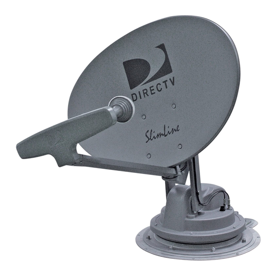
- Page 24 WINEGARD TRAV’LER SK-3005 DIRECTV Slimline Wiring Diagram Notes: 1. A Zinwell WB616 can be substituted for the WB68 to expand the outputs from 8 to 16. Please refer to the “Zinwell WB616 manual.pdf” or “Zinwell WB68 manual.pdf” file for maximum cable lengths &...
- Page 25 Please refer to the “Zinwell WB616 manual.pdf” or “Zinwell WB68 manual.pdf” file for maximum cable lengths & all other technical information. 2. B-Band converters must be used on all MPEG4 HD receivers to receive HD programming. 3. 13V/22KHz port will not be used with the WINEGARD TRAV’LER SK-3003.
Need help?
Do you have a question about the Trav'ler and is the answer not in the manual?
Questions and answers