Advertisement
Available languages
Available languages
Quick Links
INSTALLATION
INSTRUCTIONS
KIT CONTENTS
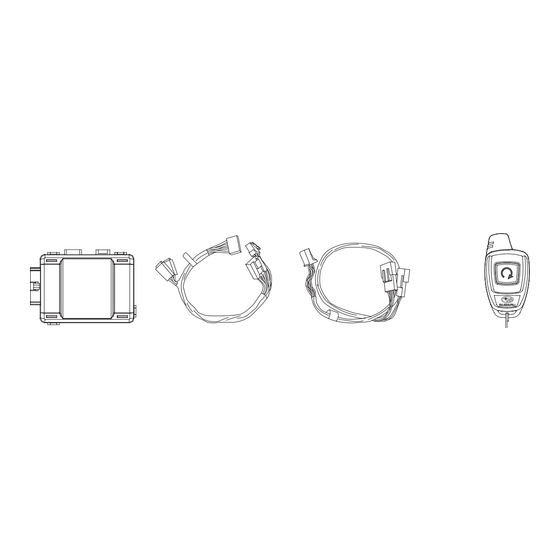
1
Remote Start
Remote Start Ignition
Control Module
Wiring Harness
Quantity= 1
WARNING: / AVERTISSEMENT
This vehicle is equipped with a remote controlled engine starter.
To reduce the risk of serious Injury or death, switch engine starter
system into service mode and disconnect the vehicle battery
before performing any service on the vehicle.
Ce vé h icule est doté d'un dé m arreur à distance. Pour ré d uire les
risques de blessures graves ou mortelles, mettre le dé m arreur à
distance en mode service et dé b rancher la batterie du vé h icule
avant d'effectuer des travaux d'entretien sur celui-ci.
Underhood
Warning Label
Quantity= 1
TOOLS REQUIRED
2
Ratchet and
Phillips Screwdriver
Short and Standard
10mm Socket
MEANING OF CHARACTERS
3
CAUTION: DO NOT SECURE ANY REMOTE START HARNESSES / MODULES TO ANY YELLOW HARNESSES / CON-
NECTORS (AIRBAG SYSTEM) IN THE VEHICLE.
PART NUMBER
ISSUE
H001SFJ600
Pre-Arranged
Jumper Wiring Harness
Quantity= 1
Quantity= 1
REMOTE START QUICK REFERENCE
Press
2 Times
Press
For 2 Seconds
Remote Start
Remote Start
Activation
Shutdown
Starting Your Vehicle
The remote control start function is activated by pressing
the START (key icon) button twice within 3 seconds on
your remote control transmitter. The system will check
certain pre-conditions before starting, and if all safety
parameters are correct, the engine will start within 5
seconds. If the vehicle s starter cranks but does not start
or starts and stalls, the remote engine start system will
power off then attempt to start the vehicle an additional
four times.
WARNING: TO AVOID DANGER OF CARBON MONOXIDE,
NEVER REMOTE START A VEHICLE IN A CLOSED SPACE
SUCH AS A CLOSED GARAGE.
Turning Your Vehicle Off
Press and hold the START (key icon) button again to turn
the vehicle off. If the vehicle is left running the remote start
system will allow the vehicle to run for a total of 15 minutes
and then automatically turn off.
Entering the Vehicle While it is Running via Remote Start
1. Unlock the vehicle doors using the factory keyless
remote. If the vehicle s doors are unlocked manually
using the key, the vehicle s security system will trigger
and the remote start system will turn off. Inserting
the ignition key into the ignition cylinder and
turning it to the ON or RUN position will disarm the
security system.
2. Enter the vehicle. Do not press the brake pedal.
3. Insert the key into the ignition and turn to the ON positi-
ion. If the ignition key is accidently turned to the start
position, the system s starter anti-grind feature will
prevent the starter from re-cranking.
4. Press the brake pedal. The remote starter disenga-
ges, the vehicle s power window features are re-ena-
bled and the vehicle will operate normally.
Quick
Reference Card
Quantity= 1 English,
1 French
Torque Wrench
: Remove
: Install
: Disconnect
: Connect
: Location of Clip or Screw
DATE
18 Jul 2013
00
PART NUMBER:
DESCRIPTION:
Remote Start
Fobs W/ Warning Tags
Quantity= 2
Tie Wraps
20cm Quantity= 9
39cm Quantity= 7
53cm Quantity= 1
Wire Cutters
Panel Removal
Tool
SUBARU OF AMERICA
H001SFJ600
REMOTE ENGINE START SYSTEM
Hood Safety Switch,
Antenna and Harness
Mounting Bracket,
Mounting Bolt & 6"
Extension Harness
Quantity= 1
Long Foam Tape
Quantity= 1
Alcohol and Towel
T
: Tighten Torque
: Loosen
: Discard
: Re-use
Remote Start
Quantity= 1
Small Foam Pads
Quantity= 6
SSM III
Diagnostic Interface
1 OF 12
Advertisement

Related Manuals for Subaru H001SFJ600


Summary of Contents for Subaru H001SFJ600
-
Page 1: Kit Contents
: Location of Clip or Screw CAUTION: DO NOT SECURE ANY REMOTE START HARNESSES / MODULES TO ANY YELLOW HARNESSES / CON- NECTORS (AIRBAG SYSTEM) IN THE VEHICLE. DATE PART NUMBER ISSUE SUBARU OF AMERICA 1 OF 12 18 Jul 2013 H001SFJ600... -
Page 2: Vehicle Preparation
Using a panel removal tool, carefully lift upward to unplug the electrical connector and place the airbag / knee bolster in a safe area. (FIGURE G) FIGURE C FIGURE G FIGURE E FIGURE F PART NUMBER ISSUE DATE 2 OF 12 SUBARU OF AMERICA H001SFJ600 18 Jul 2013... - Page 3 3 RES control module mounting to the left side of the vehicle Automatic Transmission (A /T) control module. See section 8. 4 RES windshield mount antenna connection. See section 6 DATE PART NUMBER ISSUE SUBARU OF AMERICA 3 OF 12 18 Jul 2013 H001SFJ600...
- Page 4 4. Inspect the white protective (non-woven fabric) of the curtain airbag. If the fabric is damaged, the curtain airbag assembly must be replaced. FIGURE I FIGURE J PART NUMBER ISSUE DATE 4 OF 12 SUBARU OF AMERICA H001SFJ600 18 Jul 2013...
- Page 5 7. Re-install the airbag tether clip to the A pillar panel and rotate the panel into place. 8. Re-install the A pillar panel and driver’s side dashboard tweeter cover. FIGURE N DATE PART NUMBER ISSUE SUBARU OF AMERICA 5 OF 12 18 Jul 2013 H001SFJ600...
- Page 6 NOTE: Do not secure tie wraps to the convoluted tubing covered area of the remote start ignition harness. PART NUMBER ISSUE DATE 6 OF 12 SUBARU OF AMERICA H001SFJ600 18 Jul 2013...
- Page 7 3. Plug the remote start pre-fit jumper harness 4-pin and 2-pin male connectors into the corresponding 4-pin and 2-pin vehicle female connectors. (FIGURE U) FIGURE U DATE PART NUMBER ISSUE SUBARU OF AMERICA 7 OF 12 18 Jul 2013 H001SFJ600...
- Page 8 / telescopic steering column fully RES Module FIGURE X to ensure that the new components do not interfere with operation of the tilt / telescopic feature. Fuse Box FIGURE Y PART NUMBER ISSUE DATE 8 OF 12 SUBARU OF AMERICA H001SFJ600 18 Jul 2013...
- Page 9 5. Using one of the supplied 20cm (8”) tie wraps, secure the hood safety switch wiring harness to the vehicle wire harness. (FIGURE CC) 15cm (6”) Extension Harness FIGURE BB Tie Wrap FIGURE CC DATE PART NUMBER ISSUE SUBARU OF AMERICA 9 OF 12 18 Jul 2013 H001SFJ600...
- Page 10 3. With vehicle running via ignition key, verify that the instrument cluster airbag light turns off. If the airbag light remains on, refer to vehicle service information for troubleshooting. PART NUMBER ISSUE DATE 10 OF 12 SUBARU OF AMERICA H001SFJ600 18 Jul 2013...
- Page 11 "Reg Remote Cont. Confirm Ignition Sw On Registration PRESS PRESS PRESS "Remo.con.eng.st "Registering... WAIT Eng Starter Press "Ent" Complete regist.success" Please Wait" Yes: ENT / No: C" DATE PART NUMBER ISSUE SUBARU OF AMERICA 11 OF 12 18 Jul 2013 H001SFJ600...
- Page 12 9. TRANSMITTER FUNCTIONALITY VERIFICATION - Activate the remote engine starter using both of the supplied single button transmitters. FUNCTIONAL TESTING IS NOW COMPLETE. PART NUMBER ISSUE DATE SUBARU OF AMERICA 12 OF 12 H001SFJ600 18 Jul 2013 4280550 Rev- 7/18/13...
- Page 13 ATTENTION : N’ATTACHEZ JAMAIS LE FAISCEAU OU LE MODULE DE DÉMARRAGE À DISTANCE À UN FAISCEAU JAUNE DU VÉHICULE OU À SON CONNECTEUR (SYSTÈME DE COUSSINS GONFLABLES). NUMÉRO DE PIÈCE VERSION DATE SUBARU OF AMERICA 1 DE 12 H001SFJ600 18 Jul 2013...
- Page 14 électrique, puis rangez le protège-genou/coussin gonflable à un endroit sûr. (FIGURE G) FIGURE C FIGURE G FIGURE F FIGURE E NUMÉRO DE PIÈCE VERSION DATE 2 DE 12 SUBARU OF AMERICA H001SFJ600 18 Jul 2013...
- Page 15 3 Module de commande RES de montage sur le côté gauche du véhicule, du module de boîte automatique (A/T). Voir la section 8. 4 Connexion de l'antenne RES. Voir la section 6 NUMÉRO DE PIÈCE VERSION DATE SUBARU OF AMERICA 3 DE 12 H001SFJ600 18 Jul 2013...
- Page 16 Si le tissu est endommagé, comme le révèle la visibilité de la toile rose du coussin gonflable lui-même, il faut remplacer l’ensemble coussin gonflable. FIGURE I FIGURE J NUMÉRO DE PIÈCE VERSION DATE 4 DE 12 SUBARU OF AMERICA H001SFJ600 18 Jul 2013...
- Page 17 à fusibles. 7. Réinstallez le clip d'attache airbag au tableau A colonne et faites pivoter le panneau en place. FIGURE N NUMÉRO DE PIÈCE VERSION DATE SUBARU OF AMERICA 5 DE 12 H001SFJ600 18 Jul 2013...
- Page 18 à distance. REMARQUE: Ne attaches autobloquantes pas sécurisés à la tubulure zone alambiquée couvert de la rampe d'allumage de démarrage à distance. FIGURE Q NUMÉRO DE PIÈCE VERSION DATE 6 DE 12 SUBARU OF AMERICA H001SFJ600 18 Jul 2013...
- Page 19 3. Branchez le cavalier prémonté de démarrage à distance à connecteurs mâles 4 points et 2 points aux connecteurs femelles correspondants du véhicule. FIGURE T (FIGURE U) FIGURE U NUMÉRO DE PIÈCE VERSION DATE SUBARU OF AMERICA 7 DE 12 H001SFJ600 18 Jul 2013...
- Page 20 Module de FIGURE X Fuse Box FIGURE Y NUMÉRO DE PIÈCE VERSION DATE 8 DE 12 SUBARU OF AMERICA H001SFJ600 18 Jul 2013...
- Page 21 (FIGURE CC) Chambre d’ air FIGURE AA FIGURE BB Attache FIGURE CC NUMÉRO DE PIÈCE VERSION DATE SUBARU OF AMERICA 9 DE 12 H001SFJ600 18 Jul 2013...
- Page 22 Avec le véhicule qui court via la clef de contact, vérifier que la lumière d'airbag de bloc d'instruments éteint. Si la lumière d'airbag reste sur, se référer aux informations de service de véhicule pour le dépannage. NUMÉRO DE PIÈCE VERSION DATE 10 DE 12 SUBARU OF AMERICA H001SFJ600 18 Jul 2013...
- Page 23 "ENT" sélectionner "ENT" "ENT" «All Other Model» pour sélectionner « Imm Regist » « Véhicule Subaru » (tout autre modèle) Sys immobi Presser "ENT" L'écran SDI affichera L'écran SDI affichera L'écran SDI affichera « Confirm IGN ON YES L'écran du SDI affiche :...
- Page 24 9. VÉRIFICATION DU FONCTIONNEMENT DE LA TÉLÉCOMMANDE – Activez le système de démarrage à distance tour à tour avec les deux télécommandes à un bouton fournies. L’ESSAI DE FONCTIONNEMENT EST MAINTENANT TERMINÉ. NUMÉRO DE PIÈCE VERSION DATE SUBARU OF AMERICA 12 DE 12 H001SFJ600 18 Jul 2013 4280550 Rev - 07/18/13...
Need help?
Do you have a question about the H001SFJ600 and is the answer not in the manual?
Questions and answers