Advertisement
Quick Links
INSTALLATION
INSTRUCTIONS
1
KIT CONTENTS
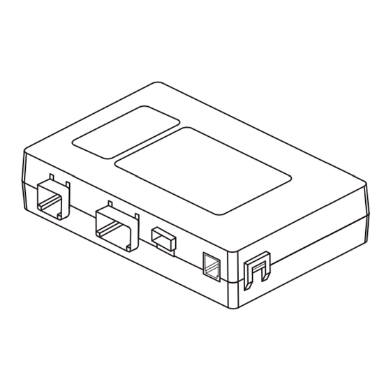
Remote Engine Start
Control Module (ECU)
Quantity=1
WARNING: / AVERTISSEMENT
This vehicle is equipped with a remote controlled engine starter.
To reduce the risk of serious Injury or death, switch engine starter
system into service mode and disconnect the vehicle battery
before performing any service on the vehicle.
Ce véhicule est doté d'un démarreur à distance. Pour réduire les
risques de blessures graves ou mortelles, mettre le démarreur à
distance en mode service et débrancher la batterie du véhicule
avant d'effectuer des travaux d'entretien sur celui-ci.
Under Hood
Warning Label
Quantity=1
2
TOOLS REQUIRED
Phillips Screwdriver
Short and Standard
Ratchet, 10mm Socket &
Extension
3
MEANING OF CHARACTERS
CAUTION: DO NOT SECURE ANY REMOTE START HARNESSES TO ANY YELLOW HARNESSES / CONNECTORS
(AIRBAG SYSTEM) IN THE VEHICLE.
PART NUMBER
ISSUE
H001SFL400
REMOTE START QUICK REFERENCE*
LONG RANGE ACTIVATION - ALL MODELS
ALTERNATE ACTIVATION -
PUSH BUTTON START MODELS
Remote Start Activation
Remote Start Activation
Press
Two (2) Times
Press
Two (2) Times
Within (2) Seconds, Then
Within Three (3) Seconds
Press and Hold For Three (3)
Remote Start Shutdown
Seconds
Press and Hold
For
Remote Start Shutdown
Three (3) Seconds
Press and Hold
For
Two (2) Seconds
NOTE: All vehicle doors, hood, trunk or rear gate must be closed prior to activating the remote engine start
system. Any open entry point will prevent starting or cause the system to shut down.
Upon successful activation, the remote start fob will fl ash and beep one (1) time**, the horn will honk one (1) time
and the side marker lights, tail lights and parking lights will fl ash one (1) time. The system will check certain safety
preconditions before starting and if all conditions are met, the engine will start within fi ve (5) seconds. After the
engine starts, the remote start fob will fl ash and beep two (2) times**, the horn will honk one (1) time and the side
marker lights, tail lights and parking lights will fl ash one (1) time. While the engine is running via the remote engine
start system, the remote start fob will continue to fl ash one (1) time every three (3) seconds, the side marker lights,
tail lights and parking lights will remain illuminated and the power window switches will be disabled. The engine
will continue to run for fi fteen (15) minutes unless one of the safety parameters below is triggered. The system also
has a timer that will allow the system to operate for a maximum of twenty (20) minutes (under multiple remote start
activations). Using the factory ignition key (Turn start models) or Access key (Push button start models) to turn on the
ignition resets the twenty (20) minute timer.
If the engine turns over but does not start (or starts and stalls) the remote engine start system will power off and then
attempt to start the engine three (3) additional times. The system will not attempt to restart the engine if it determines
a vehicle malfunction is preventing it from starting. If the engine does not start after the three (3) additional attempts,
the remote engine start request will be aborted.
Remote Start Safety Parameters
For safety and security reasons, the system will fail to start or shut down the engine during remote start operation if
any of the following occur:
•
The remote start system has operated for twenty (20) minutes between ignition "ON" cycles
The horn will honk three (3) times and the parking lights will fl ash three (3) times
•
Any of the vehicle's doors, trunk or rear gate are open
The horn will honk six (6) times and the parking lights will fl ash six (6) times
•
The vehicle's hood is open
The horn will honk two (2) times and the parking lights will fl ash two (2) times
•
The ignition key is resting in the ignition cylinder (Turn start models)
The horn will honk two (2) times and the parking lights will fl ash two (2) times
•
The transmission shifter is not in the "park" position
The horn will honk two (2) times and the parking lights will fl ash two (2) times
•
The vehicle's brake pedal is pressed before the vehicle ignition is turned "ON"
The horn will honk two (2) times and the parking lights will fl ash two (2) times
•
The vehicle's engine idle speed has reached a level over 3,500 RPM (this will cause the vehicle to shut down)
•
The vehicle's security system is triggered by opening the door, trunk or rear gate (if the security system is armed
at the time of remote start activation)
In addition to the items above, if the vehicle's engine management system determines there is a safety risk due to a
vehicle related problem, the engine will shut down.
WARNING: TO AVOID DANGER OF CARBON MONOXIDE, NEVER REMOTE START A VEHICLE IN A CLOSED
SPACE SUCH AS A CLOSED GARAGE.
NOTE: Laws in some communities require that the vehicle be within view of anyone using the Remote Engine
Start. In some areas, use of the Remote Engine Start may violate state, provincial or local laws. Before using
the Remote Engine Start, check your state, provincial and local laws.
* See the vehicle owner's manual for more details.
** Provided that the remote start fob is within the operating range of the system.
P/N: 4280648, Rev -
Quick
Reference Card
Quantity=1 English,
1 French
Torque Wrench
Alcohol and Towel
: Remove
: Install
: Disconnect
: Connect
: Location of Clip or Screw
DATE
01
25 Jul 2018
PART NUMBER:
DESCRIPTION:
Remote Engine Start
Wire Harness
Quantity=1
Wire Harness
Clip
Quantity=1
Panel Removal Tool
Utility Knife
Pick Tool
SUBARU OF AMERICA
H001SFL400
LONG RANGE KEY START
REMOTE ENGINE START SYSTEM
IMPREZA / CROSSTREK
Remote Engine Start
Transmitters w/ Warning Tags
Quantity=2
ECU Foam Tape
Quantity=1
Wire Cutters
Diagnostic Interface
Ruler
T
: Tighten Torque
: Loosen
: Discard
: Re-use
Tie Wraps
20cm Quantity=4
39cm Quantity=8
B
A
SSM IV (DST-i)
1 OF 14
Advertisement

Related Manuals for Subaru H001SFL400


Summary of Contents for Subaru H001SFL400
-
Page 1: Kit Contents
: Re-use : Location of Clip or Screw CAUTION: DO NOT SECURE ANY REMOTE START HARNESSES TO ANY YELLOW HARNESSES / CONNECTORS (AIRBAG SYSTEM) IN THE VEHICLE. DATE PART NUMBER ISSUE SUBARU OF AMERICA 1 OF 14 H001SFL400 25 Jul 2018... -
Page 2: Vehicle Preparation
(7) pressure clips. Unplug all connectors attached to the dashboard FIGURE B panel. (FIGURE D) FIGURE D FIGURE C PART NUMBER ISSUE DATE SUBARU OF AMERICA 2 OF 14 H001SFL400 25 Jul 2018... - Page 3 Using a panel removal tool, carefully lift upward to unplug the electrical connector and place the airbag/ knee bolster panel in a safe area. FIGURE F FIGURE H FIGURE G DATE PART NUMBER ISSUE SUBARU OF AMERICA 3 OF 14 H001SFL400 25 Jul 2018...
- Page 4 Disengage the six (6) pressure clips and disconnect the glove box lamp connector to remove the glove box inner cover. (FIGURE L) FIGURE L PART NUMBER ISSUE DATE SUBARU OF AMERICA 4 OF 14 H001SFL400 25 Jul 2018...
- Page 5 FIGURE N “dashed” line. NOTE: Score the release liner only. Do not score through the double sided tape. DATE PART NUMBER ISSUE SUBARU OF AMERICA 5 OF 14 H001SFL400 25 Jul 2018...
- Page 6 8. Using one (1) of the supplied 39cm tie wraps, secure the remote engine start ECU to the glove box inner cover. Trim off the excess tie wrap. (FIGURE Q) FIGURE Q PART NUMBER ISSUE DATE SUBARU OF AMERICA 6 OF 14 H001SFL400 25 Jul 2018...
- Page 7 4. Plug the remote engine start wire harness 8-pin female connector into the vehicle’s ignition switch. (FIGURE T) Factory 8-Pin Female FIGURE T Ignition Switch Connector DATE PART NUMBER ISSUE SUBARU OF AMERICA 7 OF 14 H001SFL400 25 Jul 2018...
- Page 8 (3) of the supplied 39cm tie wraps at the white tape rings. Trim off the excess tie wraps. (FIGURE X) Plastic Tabs FIGURE V FIGURE X FIGURE W PART NUMBER ISSUE DATE SUBARU OF AMERICA 8 OF 14 H001SFL400 25 Jul 2018...
- Page 9 (1) of the supplied 39cm tie wraps. Trim off the excess tie wrap. (FIGURE Z) FIGURE Z DATE PART NUMBER ISSUE SUBARU OF AMERICA 9 OF 14 H001SFL400 25 Jul 2018...
- Page 10 20cm tie wraps at the white tape ring. Trim off the excess tie wrap. (FIGURE BB) NOTE: The tie wrap is routed through a slot in the vehicle’s HVAC assembly. FIGURE BB PART NUMBER ISSUE DATE SUBARU OF AMERICA 10 OF 14 H001SFL400 25 Jul 2018...
- Page 11 NOTE: Ensure the remote engine start wire View From harness is NOT too tight to avoid stress on the ECU Behind the connectors. Glove Box Inner Cover FIGURE EE DATE PART NUMBER ISSUE SUBARU OF AMERICA 11 OF 14 H001SFL400 25 Jul 2018...
- Page 12 8. Re-install the right side dashboard panel by engaging the four (4) pressure clips. 9. Re-install the glove box and strut. 10. At the end of the installation, insert the Quick Reference Cards into the Owner’s Information Kit. PART NUMBER ISSUE DATE SUBARU OF AMERICA 12 OF 14 H001SFL400 25 Jul 2018...
- Page 13 Press YES or NO PRESS DST-i screen will display "Successful Using the arrows Registration PRESS [Remote Engine Start on the DST-i, select Complete CM Registration] “OK” Press OK” DATE PART NUMBER ISSUE SUBARU OF AMERICA 13 OF 14 H001SFL400 25 Jul 2018...
- Page 14 9. TRANSMITTER FUNCTIONALITY VERIFICATION - Activate the remote engine start using both of the supplied single button remote start transmitters. FUNCTIONAL TESTING IS NOW COMPLETE. PART NUMBER ISSUE DATE SUBARU OF AMERICA 14 OF 14 H001SFL400 25 Jul 2018 4280846 Rev - 7/25/18...
Need help?
Do you have a question about the H001SFL400 and is the answer not in the manual?
Questions and answers