
Related Manuals for LG LCP2850-AN


Summary of Contents for LG LCP2850-AN
-
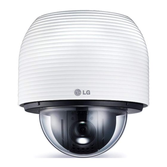
Page 1: Dome Camera
OWNER’S MANUAL Dome Camera Please read this manual carefully before operating your set and retain it for future reference. MODEL LCP2850-AN/AP... -
Page 2: Safety Information
Safety Information Safety Information REGULATORY INFORMATION: FCC Part 15 CAUTION This equipment has been tested and found to comply with the limits for a Class A digital device, pursuant to Part RISK OF ELECTRIC SHOCK 15 of the FCC Rules. These limits are designed to provide DO NOT OPEN reasonable protection against harmful interference when the equipment is operated in a commercial environment. - Page 3 LG Electronics hereby declares that this/ these product(s) is/are in compliance 4. The correct disposal of Your old batteries/ with the essential requirements and other...
-
Page 4: Important Safety Instructions
Safety Information IMPORTANT SAFETY 14. Refer all servicing to qualified service personnel. Servicing is required when the apparatus has been INSTRUCTIONS damaged in any way, such as power-supply cord or plug is damaged, liquid has been spilled or objects have fallen into the apparatus, the apparatus has been exposed to rain or moisture, does not operate normally, or has been dropped. -
Page 5: About Static Electricity Removal
Safety Information • Before operating, please check proper temperature, About Static Electricity Removal humidity and power source ratings. Before installing the camera, touch a metal case or other Use the camera under conditions where temperature metallic parts with your hand to remove static electricity is from -20 °C to 50 °C and humidity is below 80 %. -
Page 6: Table Of Contents
Contents Contents Connecting LKD1000 controller Connecting RS-485 device Connecting power source Protocol and baud rate settings Camera ID Setting Removing the Protection Tape Mounting the camera Safety Information Wall mount (optional) Pendant mount (Optional) IMPORTANT SAFETY INSTRUCTIONS Safety Precautions Operation Preparation Setup Menu Overview Menu navigation... - Page 7 Contents Auto Pan setting Privacy Mask setting Special setting OSD Settings User title setting ZOOM MAG setting FUNCTION setting DOME ID setting LANGUAGE Setting ALARM Setting Alarm In setting Alarm Out setting RESET Setting Information Initialization Camera reset Factory reset Appendix Specifications...
-
Page 8: Preparation
Preparation Preparation Introduction reproduced repeatedly. The Pan, Tilt and Zoom controls are available for pattern recording. Note The available total time of pattern differs depending The dome cameras are designed for installation in an on camera’s operation. When the pattern recording is outdoor video surveillance system. -
Page 9: Accessories
Preparation Accessories • Controls by General Controller This camera can be controlled by RS-485. Especially the camera has an excellent cost-saving effect because it can be controlled by the general RX point of contact signal. • Connects with the maximum 256 cameras This camera can be utilized after being connected with maximum 256 cameras. -
Page 10: Part Names And Functions
Preparation Part Names and Functions BNC connector cover cap Video output BNC connector Supplies analog video signal (composite) to the connected device. RS-485 Data Communication Alarm In Data Terminal Input data terminal for alarm (relay) signal. Alarm Out Data Terminal Output data terminal for alarm (relay) signal. -
Page 11: Installation
Installation Installation Connections Precautions • The following steps of installation and connection work should be done by qualified service personnel or system installers and should conform to all local codes. • Before you install and connect the camera, check and prepare the required peripheral devices and cables. •... -
Page 12: Connecting Display Device
Terminal of the camera. 2. Connect the alarm device to the Adaptor cable. When connecting lines, check and connect the color Alarm In Data Terminal for the LCP2850-AN/AP lines of the each device correctly. Refer to the below tables for color line information. - Page 13 Installation Alarm Input function ALARM IN 2 Gray This speed dome camera has a terminal that can sense the ALARM IN COM Yellow alarm signals. If the alarm sensor that has installed in a door, window, ALARM IN 3 White safe etc.
-
Page 14: Alarm Output Connections
Installation ALARM output connections Alarm Out Data Terminal for LCP2850-AN/AP Connect the alarm device to the alarm output data port. Description Color Alarm signal output at an event occurrence. You can set the Alarm Output to the normal open or normal close mode. -
Page 15: Connecting Lkd1000 Controller
Description Description RS-485 + RS-485 + RS-485 - RS-485 - RS-485 device Connecting RS-485 device RS-485 Data Communication of the LCP2850-AN/AP Description Color Use the cable that is described below for RS-485 site RS-485 + Green communication. RS-485 - Blue •... -
Page 16: Connecting Power Source
Pelco D Pelco P OSD Set Note If you are not using the controller with LG Multix protocol, there may be some limitation of function control. 5. Assemble the dome cover and the camera assembly cover in the reverse order. -
Page 17: Camera Id Setting
Installation Camera ID Setting OFF OFF OFF OFF OFF The camera’s ID is set to “0” as factory default. If you use OFF OFF OFF two or more cameras simultaneously, change the ID of the OFF OFF OFF cameras. OFF OFF OFF Set the camera ID setting referring to the pictures and the table on the below. - Page 18 Installation OFF OFF OFF OFF OFF OFF OFF OFF OFF OFF OFF OFF OFF OFF OFF OFF OFF OFF OFF OFF OFF OFF OFF OFF OFF OFF OFF OFF OFF OFF OFF OFF OFF OFF OFF OFF OFF OFF OFF OFF OFF OFF OFF OFF OFF OFF...
- Page 19 Installation OFF OFF OFF OFF OFF OFF OFF OFF OFF OFF OFF OFF OFF OFF OFF OFF OFF OFF OFF OFF OFF OFF OFF OFF OFF OFF OFF OFF OFF OFF OFF OFF OFF OFF OFF OFF OFF OFF OFF OFF OFF OFF OFF OFF OFF OFF OFF OFF OFF OFF OFF OFF...
-
Page 20: Removing The Protection Tape
Installation Removing the Protection Tape OFF OFF OFF OFF OFF You should remove the protection tape before installing OFF OFF OFF OFF the camera. Remove the protection tape carefully. OFF OFF OFF 1. Loosen the screws using the wrench and remove the OFF OFF OFF dome cover. -
Page 21: Mounting The Camera
Installation Mounting the camera 4. Drill a hole on the wall where you want to install the pipe. Pass the connection cable through the wall mount assembly so that they hang down. You can mount the camera on the ceiling or wall. Wall mount (optional) Install the camera by the following order. - Page 22 8. Tighten the locking screw. Note You can install the PIPE Installation Bracket direct to the other type LG Wall Mount assembly. This LG Wall Mount assembly make to easy to install your camera.
-
Page 23: Pendant Mount (Optional)
Installation Pendant mount (Optional) 4. Drill a hole on the wall where you want to install the pipe. Pass the connection cable through the pendant Install the camera by the following order. mount assembly so that they hang down. 1. Disassemble the PIPE Installation Bracket to remove the [A] part. - Page 24 Installation 5. Install the pendant mount assembly. 7. Attach the camera to the camera assembly bracket by following step a and b. Align the locking point of the wall mount assembly and the camera. 6. Connect the connection cable and the safety cable to the camera body.
- Page 25 Installation Note 9. Assemble the camera cover as shown below. You can install the PIPE Installation Bracket direct to the other type LG Wall Mount assembly. This LG Wall Mount assembly make to easy to install your camera.
-
Page 26: Operation
Operation Operation Setup Menu Overview The following table shows the list of menu items and options. You can adapt the camera to your requirements by setting up the respective items in these menus. 1st level 2nd level 3rd level Contents CAMERA SET FOCUS FOCUS MODE... - Page 27 Operation CAMERA SET DAY/NIGHT AUTO D/N LEVEL LOW/MIDDLE/HIGH DWELL TIME 5,10,15,30,60 SEC RETURN NIGHT 3D-DNR MIDDLE HIGH COLOR COLOR -50 to 50 SHARPNESS 0 to 68 STABILIZER RETURN PAN/TILT SET PRESET SET PRESET NAME OFF/ON SPEED 1 to 127 DWELL TIME 1 to 255 IRIS AUTO, 20, 40, 60, 80, 100 %...
- Page 28 Operation PAN/TILT SET GROUP TOUR SET GROUP 1 to 10 1 to 10 CLEAR 1 to 10 RETURN PATTERN RECORD 1 to 4 1 to 4 RETURN AUTO PAN SET AUTO PAN 1 to 8 CLEAR RETURN PRIVACY MASK MASK NUMBER 1 to 8 SET MASK MASK STATE...
- Page 29 Operation PAN/TILT SET SPECIAL COMMUNICATION LG MULTIX/ PELCO C/ PROTOCOL PELCO D/ PELCO P 2 400/ 4 800/ 19 200/ 38 400/ BAUDRATE 9 600 BPS SAVE & EXIT RETURN OSD SET USER TITLE ON/OFF ZOOM MAG ON/OFF FUNCTION ON/OFF...
-
Page 30: Menu Navigation
We use the LKD1000 controller in this manual to explain PRESET /CAM1 the features of the LG Dome camera because of the LKD1000’s ability to control all of the LG Dome camera’s advanced features. (For detailed controller instructions, refer to the LKD1000 Controller Manual.) -
Page 31: Camera Menu Settings
Operation Camera menu settings Focus Distance setting Selects the minimum shooting distance for the focus. Select [FOCUS DIST] option on the [FOCUS] menu, then select a focus distance value. Focus setting Zoom Start setting The camera adjusts the focus automatically by sensing the You can set the zoom start position of the camera. -
Page 32: White Balance Setting
Operation • AUTO: The lens iris is set automatically. SHUTTER (Shutter Speed) setting Select the desired shutter speed for camera exposure. You • MANUAL: Use [Near] or [Far] button to select the DC Iris can change the shutter speed to higher speed to capture level. -
Page 33: Day/Night Setting
Operation When the scene is dim. DWELL TIME: Use [Near] or [Far] button to select a dwell time. • AUTO: In this mode, the color temperature range for the proper white balance is approximately Note 3 500 K to 6 500 K. Proper white balance may not If you set the AGC to [OFF] or the SHUTTER is set to be obtained under the following conditions: one of the SHUTTER options except AUTO on the... -
Page 34: Color Setting
Operation Color setting You can switch the displayed picture to grayscale or color. 1. Select [STABILIZER] option on the [CAMERA SET] menu. 2. Use [Near] or [Far] button to ser it [ON] or [OFF]. 1. Select [COLOR] option on the [CAMERA SET] menu. 2. - Page 35 Operation 2. Use the [Near] or [Far] button to select the preset to the preset position and the picture of the camera in number you wish to register and press the [Open] or that position appears on the monitor. [Close] button. 3.
-
Page 36: Group Tour Setting
Operation Group tour setting To delete a group You can delete a memorized group. You can create a group using preset positions that are registered already. A maximum of 10 groups is available. 1. Select [CLEAR] option on the [GROUP TOUR] menu. 2. -
Page 37: Auto Pan Setting
Operation To play the pattern 8. Repeat steps 1 to 7 to add additional positions. 9. Select [RETURN] option and press [Open] or [Close] 1. Select [RUN] option on the [PATTERN] menu. button to exit the setting menu. 2. Select the recording number and then press [Open] or Note [Close] button to play the programmed pattern. -
Page 38: Special Setting
Operation Special setting 1. Select [PRIVACY MASK] option on the [PAN/TILT MENU]. 2. Press [Open] or [Close] button to display the PRIVACY MASK MENU. 3. Use [Near] or [Far] button to select a zone number on the [MASK NUMBER] option. 4. -
Page 39: Home Position
Operation Home position 2. Use [Near] or [Far] button to set it [ON]. If you do not want to use this function, set it to [OFF]. The home position is the camera’s basic position. The camera returns to this position whenever you want. Use the following procedure to make the home position. -
Page 40: Osd Settings
Operation OSD Settings • CLR: If you enter the wrong code, select [CLR] then press [Open] or [Close]. All letters will be erased at once. • POS: Move the USER TITLE position on the screen using the [Near] or [Far] buttons. •... -
Page 41: Dome Id Setting
Operation ALARM Setting DOME ID setting Displays or removes the Camera ID OSD on the screen. This camera has a terminal that can sense the alarm signals. The camera can be programmed to go to a preset with a signal from any connected alarm device. 1. -
Page 42: Alarm Out Setting
Operation Alarm Out setting Initialization 1. Select one of the alarm out options on the [ALARM You can initialize the camera settings. SET] menu. 1. Select [INITIALIZATION] option on the [RESET] menu. 2. Use [Near] or [Far] button to set it [ON]. 2. -
Page 43: Appendix
Appendix Appendix Specifications Model LCP2850-AN LCP2850-AP Signal System NTSC Image Sensor 4.5 mm(1/4 Type) Super HAD II CCD Total Pixels Number 520 000 Pixels 610 000 Pixels Effective Pixels Number 490 000 Pixels 570 000 Pixels Horizontal Resolution 600 TV Lines Lens x28 Zoom, F1.5 (Wide End), F3.7(Tele End), f= 3.5 mm to 98 mm... - Page 44 Group Touring Maximum 10 Groups Coax : Pelco-C (Coaxitron) Protocol RS-485 : LG Multix, Pelco(D/P) Operating Temperature/Humidity -20 ˚C to 50 ˚C / 0 % RH to 80 % RH Safekeeping Temperature/Humidity -30 ˚C to 60 ˚C / 0 % RH to 90 % RH...
- Page 48 AB28...
Need help?
Do you have a question about the LCP2850-AN and is the answer not in the manual?
Questions and answers