
Related Manuals for MULTIQUIP GA4.5RA


Summary of Contents for MULTIQUIP GA4.5RA
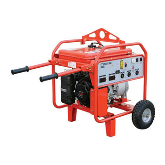
- Page 1 OPERATION AND PARTS MANUAL MODEL GA4.5R/GA4.5RA PORTABLE AC GENERATOR (ROBIN GASOLINE ENGINE) Revision #1 (11/27/06) THIS MANUAL MUST ACCOMPANY THE EQUIPMENT AT ALL TIMES.
- Page 2 PAGE 2 — GA-4.5R/GA-4.5RA A.C. GENERATOR— OPERATION & PARTS MANUAL — REV. #1 (11/27/06)
-
Page 3: California Proposition 65 Warning
NOTE PAGE GA-4.5R/GA-4.5RA A.C. GENERATOR — OPERATION & PARTS MANUAL — REV. #1 (11/27/06) — PAGE 3... -
Page 4: Table Of Contents
TABLE OF CONTENTS ROBIN EX270D Engine GA-4.5R/GA-4.5RA — AC (EPA) Portable Generators Crankcase Assembly .........48-49 California Proposition 65 Warning ......3 Crankshaft and Piston Assembly .......50-51 Table Of Contents ............. 4 Governor Assembly ...........52-53 Parts Ordering Procedures ........5 Intake and Exhaust Assembly ......54-55 Safety Alert Message Symbols ...... -
Page 5: Ga-4.5R/Ga-4.5Ra - Ac
Choose from three easy options: Order via Internet (Dealers Only) Best Deal! If you have an MQ Account, to obtain a Order parts on-line using Multiquip’s SmartEquip website! Username and Password, E-mail us at: ■ View Parts Diagrams parts@multiquip.com. ■ Order Parts To obtain an MQ Account, contact your ■... -
Page 6: Safety Alert Message Symbols
GA-4.5R/GA-4.5RA — SAFETY MESSAGE ALERT SYMBOLS FOR YOUR SAFETY AND THE SAFETY OF OTHERS! HAZARD SYMBOLS Potential hazards associated with the operation of this Safety precautions should be followed equipment will be referenced with " Hazard Symbols " which at all times when operating this equipment. - Page 7 GA-4.5R/GA-4.5RA — SAFETY MESSAGE ALERT SYMBOLS WARNING - ROTATING PARTS CAUTION - RESPIRATORY HAZARDS NEVER operate equipment with covers, ALWAYS wear approved respiratory or guards removed. Keep fingers , hands , protection. hair and clothing away from all moving parts to prevent injury. CAUTION - ACCIDENTAL STARTING CAUTION - SIGHT AND HEARING HAZARDS ALWAYS place the Engine ON/OFF...
-
Page 8: Rules For Safe Operation
■ NEVER use accessories or attachments, which are not warranties. recommended by Multiquip for this equipment. Damage to the equipment and/or injury to user may result. PAGE 8 — GA-4.5R/GA-4.5RA A.C. GENERATOR— OPERATION & PARTS MANUAL — REV. #1 (11/27/06) -
Page 9: Maintenance Safety
GA-4.5R/GA-4.5RA — RULES FOR SAFE OPERATION ■ ALWAYS be sure the operator is familiar with proper safety Maintenance Safety precautions and operation techniques before using generator. ■ NEVER lubricate components or attempt service on a running ■ NEVER leave the generator unattended, turn off engine when machine. -
Page 10: Rules For Safe Operation
GA-4.5R/GA-4.5RA — RULES FOR SAFE OPERATION Emergencies DANGER DANGER DANGER ELECTROCUTION HAZARDS ELECTROCUTION HAZARDS ELECTROCUTION HAZARDS DANGER DANGER ELECTROCUTION HAZARDS ELECTROCUTION HAZARDS ■ ALWAYS know the location of the nearest fire extinguisher . During operation of this generation, there exists the possibility of electrocution , electrical shock or burn , which can ■... -
Page 11: Specifications
GA-4.5R/GA-4.5RA — SPECIFICATIONS i f i o i t . 4 - . 4 - , e l i v l n i t a t l n i t / 5 . n i t r o t i s n . -
Page 12: Dimensions
GA-4.5R/GA-4.5RA — DIMENSIONS Figure 1. Dimensions PAGE 12 — GA-4.5R/GA-4.5RA A.C. GENERATOR— OPERATION & PARTS MANUAL — REV. #1 (11/27/06) -
Page 13: General Information
This portable generator is supplied with a electrical control In keeping with Multiquip's panel . The control panel includes items as listed below. policy... -
Page 14: Load Application
GA-4.5R/GA-4.5RA — LOAD APPLICATION To determine the running wattage for your load, multiply Single Phase Load the running wattage as indicated by steps 1, 2, and 3 below: Always be sure to check the nameplate on the generator INCANDESCENT LOADS and equipment to insure the wattage, amperage and Lights, heaters and similar appliances. -
Page 15: Controls And Indicators
GA-4.5R/GA-4.5RA — CONTROLS AND INDICATORS Figure 2A. Generator Controls and Components Lifting Bail Eye – Attach a rope or chain to this lifting eye GFCI Duplex Receptacle – NEMA 5-20R receptacle will when lifting of the generator is required. Never stand provide 120V, 20 amps. - Page 16 GA-4.5R/GA-4.5RA — CONTROLS AND INDICATORS Figure 2B. Generator Controls and Components (continued) 11. Full Power Switch – The generators are provided with a When the switch is in the 240 volt (down) position, you can full power switch. Figures 2C and 2D show simplified wiring acess half of the rated power of the generating set at 120 diagrams of the dual voltage system.
- Page 17 GA-4.5R/GA-4.5RA — CONTROLS AND INDICATORS Figure 2E. Generator Controls and Components (continued) 12. Choke Lever – Used for starting the engine. Close the 19. Oil Dipstick/ Filler Cap– Remove the filler cap dipstick choke lever when starting a cold engine or in cold weather when checking the engine oil level.
-
Page 18: Generator Refueling
GA-4.5R/GA-4.5RA — GENERATOR REFUELING DANGER - REFUELING HAZARD Adding fuel to the tank should be done only when the engine is stopped and has had an opportunity to cool down. In the event of a fuel spill, DO NOT attempt to start the engine until the fuel residue has been completely wiped up, and the area surrounding the engine is dry. -
Page 19: Installation
GA-4.5R/GA-4.5RA — INSTALLATION Outdoor Installation Indoor Installation Install the generator in a area that is free of debris , Exhaust gases from gasoline engines are extremely bystanders , and overhead obstructions . Make sure the poisonous. Whenever an engine is installed indoors the generator is on secure level ground so that it cannot slide exhaust fumes must be vented to the outside. -
Page 20: Installation
GA-4.5R/GA-4.5RA — INSTALLATION Connecting the Ground The nut and ground terminal on the generator should always be used to connect the generator to a suitable ground. The ground cable should be #8 size wire minimum. At the generator, connect the terminal of the ground cable between the lock washer and the nut (Figure 4) and tighten the nut fully. -
Page 21: Pre-Inspection
GA-4.5R/GA-4.5RA — PRE-INSPECTION General Inspection Prior to Operation Extension Cable Ground Power Tools When electric power is to be provided to various tools or loads at some distance from the generator, extension cords are normally When using power tools or electrical equipment requireing AC used. -
Page 22: Pre-Inspection (Engine)
GA-4.5R/GA-4.5RA — PRE-INSPECTION (ENGINE) CAUTION CAUTION CAUTION CAUTION CAUTION NEVER operate the generator in a confined area or enclosed area structure that does not provide ample free flow of air . Figure 7. Engine Oil Dipstick (Oil Level) ALWAYS wear approved eye and hearing protection before operating the generator. -
Page 23: Initial Start-Up (Engine)
GA-4.5R/GA-4.5RA — INITIAL START-UP (ENGINE) 2. Place the choke lever (Figure 11) in the " CLOSED " position CAUTION - READ MANUAL if starting a cold engine. DO NOT attempt to operate this generator until the Safety, General Information and Inspection sections of this manual have been read and thoroughly understood . -
Page 24: Initial Start-Up (Engine/Operation)
GA-4.5R/GA-4.5RA — INITIAL START-UP ENGINE/OPERATION 6. If the engine has started, slowly return the choke lever (Figure 11 ) to the “OPEN” position. If the engine has not started repeat steps 1 through 6. 7. Before the generator is placed into operation, run the engine for 3-5 minutes. - Page 25 GA-4.5R/GA-4.5RA — INITIAL START-UP ENGINE/OPERATION 3. Place the main circuit breaker (Figure 21) in the ON 13. Refer to the AC voltmeter (Figure 19) on the control position. box. The voltage indicated on the voltmeter should be 240 VAC with no load applied. If desired, verify with a voltmeter that 240V is present at the NEMA L14-20R twist-lock receptacle.
-
Page 26: Preparation For Long Term Storage
GA-4.5R/GA-4.5RA — PREPARATION FOR LONG -TERM STORAGE Generator Storage For storage of the generating set for over 30 days, the following is required: ■ Drain the fuel tank completely, or add STA-BIL to the fuel. ■ Run the engine until the gasoline in the carburetor is completely consumed. - Page 27 GA-4.5R/GA-4.5RA — MAINTENANCE (ENGINE) Use Table 5 as a general maintenance guideline when servicing your engine. For more detail engine maintenance information, refer to the engine owner's manual supplied with your engine. t n i ) 3 ( l i O r i A ) 1 ( g i t...
-
Page 28: Maintenance
GA-4.5R/GA-4.5RA — MAINTENANCE (ENGINE) Maintenance Cleaning the Fuel Strainer Perform the scheduled maintenance procedures as defined by Clean the fuel strainer if it contains dust or water. Remove Table 6 and below: dust or water in the strainer cap and wash it in gasoline. Securely fasten the fuel strainer cap so that fuel will not DAILY leak. - Page 29 NOTE PAGE GA-4.5R/GA-4.5RA A.C. GENERATOR — OPERATION & PARTS MANUAL — REV. #1 (11/27/06) — PAGE 29...
-
Page 30: Wiring Diagram (Ga-4.5R)
MQ GA-4.5R — WIRING DIAGRAM Figure 28. Generator/Engine Wiring Diagram (GA-4.5R Only) PAGE 30 — GA-4.5R/GA-4.5RA A.C. GENERATOR— OPERATION & PARTS MANUAL — REV. #1 (11/27/06) -
Page 31: Wiring Diagram (Ga-4.5Ra)
MQ GA-4.5RA — WIRING DIAGRAM Figure 29. Generator/Engine Wiring Diagram (GA-4.5RA Only) GA-4.5R/GA-4.5RA A.C. GENERATOR — OPERATION & PARTS MANUAL — REV. #1 (11/27/06) — PAGE 31... -
Page 32: Troubleshooting (Engine)
GA-4.5R/GA-4.5RA — TROUBLESHOOTING (ENGINE) diagnosis based on the Engine Troubleshooting (Table 6) Practically all breakdowns can be prevented by proper information shown below and on the proceeding page. If the handling and maintenance inspections, but in the event of a problem cannot be remedied, please leave the unit just as it breakdown, please take a remedial action following the is and consult our company's business office or service... - Page 33 GA-4.5R/GA-4.5RA — TROUBLESHOOTING (ENGINE) f l a i t c . r e i c i f " i s s a " r i A a t - l i f r e t r i a a t - t l i f .
-
Page 34: Troubleshooting (Generator)
GA-4.5R/GA-4.5RA — TROUBLESHOOTING (GENERATOR) diagnosis based on the Generator Troubleshooting (Table 7) Practically all generator breakdowns can be prevented by information shown below and on the preceding page. If the proper handling and maintenance inspections, but in the event problem cannot be remedied, please leave the unit just as it of a breakdown, please take a remedial action following the is and consult our company's business office or service plant. - Page 35 NOTE PAGE GA-4.5R/GA-4.5RA A.C. GENERATOR — OPERATION & PARTS MANUAL — REV. #1 (11/27/06) — PAGE 35...
-
Page 36: Explanation Of Codes In Remarks Column
Multiquip. A blank entry generally indicates that the item is not sold separately or is not sold by Multiquip. Other entries will be clarified in the “Remarks” Column. PAGE 36 — GA-4.5R/GA-4.5RA A.C. GENERATOR— OPERATION & PARTS MANUAL — REV. #1 (11/27/06) -
Page 37: Suggested Spare Parts
GA-4.5R/GA-4.5RA — SUGGESTED SPARE PARTS GA-4.5R/GA-4.5RA 1 TO 3 UNITS WITH ROBIN EX270D ENGINE 1 to 3 Units Qty. Description 1 .... A9924800014 ..CAP, FUEL TANK 1 .... A9924800004 ..FUEL FILTER, FUEL TANK 3 .... 0650140150 ..SPARK PLUG 3 .... -
Page 38: Nameplate And Decals
GA-4.5R/GA-4.5RA — NAME PLATE AND DECALS NAMEPLATE AND DECALS PAGE 38 — GA-4.5R/GA-4.5RA A.C. GENERATOR— OPERATION & PARTS MANUAL — REV. #1 (11/27/06) -
Page 39: Nameplate And Decals
NAMEPLATE ............1 .... CONTACT MQ PARTS DEPT. 0800628504 DECAL; GROUND ..........1 .... S-1123 1630680104 DECAL; FUEL COCK ..........1 .... S-1407 A4561000003 DECAL; MQ MULTIQUIP 0820610404 DECAL; WARNING ..........1 .... S-3627 35137 DECAL; WARNING READ MANUAL 8700611804 DECAL;... -
Page 40: Generator Assembly
GA-4.5R/GA-4.5RA — GENERATOR ASSY. GENERATOR ASSY. PAGE 40 — GA-4.5R/GA-4.5RA A.C. GENERATOR— OPERATION & PARTS MANUAL — REV. #1 (11/27/06) - Page 41 GA-4.5R/GA-4.5RA — GENERATOR ASSY. GENERATOR ASSY. PART NO PART NAME QTY. REMARKS A3110200003 ROTOR ASSY............1 ..INCLUDES ITEMS W/ 7661080003 FIELD COIL ASSY. 0601823213 RECTIFIER 0601822638 SURGE ABSORBER 0071706304 BEARING 7661017104 SET BOLT, ROTOR 0801086104 SET WASHER, BEARING 0040010000 SPRING WASHER A4135000103...
-
Page 42: Control Box Assembly (Ga-4.5R)
MQ GA-4.5R — CONTROL BOX ASSY. CONTROL BOX ASSY. (GA-4.5R ONLY) PAGE 42 — GA-4.5R/GA-4.5RA A.C. GENERATOR— OPERATION & PARTS MANUAL — REV. #1 (11/27/06) - Page 43 MQ GA-4.5R — CONTROL BOX ASSY. CONTROL BOX ASSY. (GA-4.5R ONLY) PART NO PART NAME QTY. REMARKS A3214000003 CONTROL BOX 0601850102 GROMMET 0601823204 RECTIFIER, S5VB60 0027103012 MACHINE SCREW 0601823853 SLOW-DOWN UNIT 0027104010 MACHINE SCREW 0207004000 HEX NUT A3224000003 CONTROL PANEL 0601802651 CIRCUIT BREAKER, 15 AMP 4341817004...
-
Page 44: Control Box Assembly (Ga-4.5Ra)
MQ GA-4.5RA — CONTROL BOX ASSY. CONTROL BOX ASSY. (GA-4.5RA ONLY) PAGE 44 — GA-4.5R/GA-4.5RA A.C. GENERATOR— OPERATION & PARTS MANUAL — REV. #1 (11/27/06) - Page 45 MQ GA-4.5RA — CONTROL BOX ASSY. CONTROL BOX ASSY. (GA-4.5RA ONLY) PART NO PART NAME QTY. REMARKS A3214000103 CONTROL BOX 0601850102 GROMMET 0601823204 RECTIFIER, S5VB60 0027103012 MACHINE SCREW 0601823853 SLOW-DOWN UNIT 0027104010 MACHINE SCREW 0207004000 HEX NUT A3224000103 CONTROL PANEL 0601802651 CIRCUIT BREAKER, 15 AMP 4341817004...
-
Page 46: Pipe Frame Assembly
GA-4.5R/GA-4.5RA — PIPE FRAME ASSY. PIPE FRAME ASSY. PAGE 46 — GA-4.5R/GA-4.5RA A.C. GENERATOR— OPERATION & PARTS MANUAL — REV. #1 (11/27/06) - Page 47 MQ GA-4.5R/GA-4.5RA — PIPE FRAME ASSY. PIPE FRAME ASSY. PART NO PART NAME QTY. REMARKS A4417000002 PIPE FRAME ..........1 ....GA-4.5R ONLY A4417000202 PIPE FRAME ..........1 ....GA-4.5RA ONLY A3417100004 BRACKET 0017106016 HEX. HEAD BOLT A3304100003 ENGINE BASE A9312601704 RUBBER SUSPENSION 7935416004...
-
Page 48: Crankcase Assembly
ROBIN EX270D20220 — CRANKCASE ASSY. CRANKCASE ASSY.. PAGE 48 — GA-4.5R/GA-4.5RA A.C. GENERATOR— OPERATION & PARTS MANUAL — REV. #1 (11/27/06) - Page 49 ROBIN EX270D20220 — CRANKCASE ASSY. CRANKCASE ASSY. PART NO PART NAME QTY. REMARKS 2791010121 CRANKCASE ASSY..........1 ..INCLUDES ITEMS W/ 2371420203 VALVE GUIDE 2771601001 STEM SEAL 0440300160 OIL SEAL 0600300340 BALL BEARING 2771501103 PIPE KNOCK 0105080250 STUD 0105060410 STUD 0440060020 OIL SEAL...
-
Page 50: Crankshaft And Piston Assembly
ROBIN EX270D20110/EX270D20220 — CRANKSHAFT AND PISTON ASSY. CRANKSHAFT AND PISTON ASSY. PAGE 50 — GA-4.5R/GA-4.5RA A.C. GENERATOR— OPERATION & PARTS MANUAL — REV. #1 (11/27/06) - Page 51 ROBIN EX270D20110/EX270D20220 — CRANKSHAFT AND PISTON ASSY. CRANKSHAFT AND PISTON ASSY. PART NO PART NAME QTY. REMARKS 2792020121 CRANKSHAFT CP 0180180010 FLANGE NUT 0323030010 WOODRUFF KEY 2792250120 CONNECTING ROD ASSY......1 ..INCLUDES ITEM W/ 2792300103 CONNECTING ROD BOLT 2792330103 PISTON PIN 2792340103...
-
Page 52: Governor Assembly
ROBIN EX270D20110/EX270D20220 — GOVERNOR ASSY. GOVERNOR ASSY. PAGE 52 — GA-4.5R/GA-4.5RA A.C. GENERATOR— OPERATION & PARTS MANUAL — REV. #1 (11/27/06) - Page 53 ROBIN EX270D20110/EX270D20220 — GOVERNOR ASSY. GOVERNOR ASSY. PART NO PART NAME QTY. REMARKS 2794230113 GOVERNOR LEVER 2774220113 GOVERNOR SHAFT 2794270101 GOVERNOR ROD CP 2774280113 ROD SPRING 0031305000 CLIP 0130060240 BOLT AND WASHER ASSY. 0186060020 2794250223 GOVERNOR SPRING 2774330113 SPEED CONTROL LEVER 2774350103 STOP PLATE 0200060170...
-
Page 54: Intake And Exhaust Assembly
ROBIN EX270D20110/EX270D20220 — INTAKE AND EXHAUST ASSY. INTAKE AND EXHAUST ASSY. PAGE 54 — GA-4.5R/GA-4.5RA A.C. GENERATOR— OPERATION & PARTS MANUAL — REV. #1 (11/27/06) - Page 55 ROBIN EX270D20110/EX270D20220 — INTAKE AND EXHAUST ASSY. INTAKE AND EXHAUST ASSY. PART NO. PART NAME QTY. REMARKS 2793160101 CAMSHAFT CP ......... 1 ..... INCLUDES ITEMS W/ 2773510103 PIN, CAMSHAFT, 9DX78.5L 0240060010 O RING, 5.8DX9.6DX1.9T 2773860103 SPRING PIN, 4DX7.5DX11L 2793640103 RELEASE LEVER 2773650103 CLIP, 13.8DX20.3DX0.4T 2773870103...
-
Page 56: Muffler Assembly
ROBIN EX270D20110/EX270D20220 — MUFFLER ASSY. MUFFLER ASSY. PAGE 56 — GA-4.5R/GA-4.5RA A.C. GENERATOR— OPERATION & PARTS MANUAL — REV. #1 (11/27/06) - Page 57 ROBIN EX270D20110/EX270D20220 — MUFFLER ASSY. MUFFLER ASSY. PART NO. PART NAME QTY. REMARKS 2793010121 MUFFLER, CP 2793420111 MUFFLER COVER CP 2773520103 GASKET, MUFFLER 26D 9DX58P 0.2T 9802008280 FLANGE NUT 0152060090 TAPPING BOLT, M6X1.0X10L 0110060010 FLANGE BOLT, M6X1.0X8L 0110080150 FLANGE BOLT, M8X1.25X12L GA-4.5R/GA-4.5RA A.C.
-
Page 58: Air Cleaner Assembly
ROBIN EX270D20110/EX270D20220 — AIR CLEANER ASSY. AIR CLEANER ASSY. PAGE 58 — GA-4.5R/GA-4.5RA A.C. GENERATOR— OPERATION & PARTS MANUAL — REV. #1 (11/27/06) - Page 59 ROBIN EX270D20110/EX270D20220 — AIR CLEANER ASSY. AIR CLEANER ASSY. PART NO. PART NAME QTY. REMARKS 2793262030 AIR CLEANER ASSY. LOW PROFILE ....1 ..INCLUDES ITEMS W/ 510-200 2793263308 BODY CP 510-220 2793265008 GASKET 510-250 2793264508 COVER, LOW PROFILE 2793260907 ELEMENT ASSY.
-
Page 60: Recoil Starter Assembly
ROBIN EX270D20110/EX270D20220 — RECOIL STARTER ASSY. RECOIL STARTER ASSY. PAGE 60 — GA-4.5R/GA-4.5RA A.C. GENERATOR— OPERATION & PARTS MANUAL — REV. #1 (11/27/06) - Page 61 ROBIN EX270D20110/EX270D20220 — RECOIL STARTER ASSY. RECOIL STARTER ASSY. PART NO PART NAME QTY. REMARKS 2795120101 BLOWER HOUSING CP 0732005140 LABEL, TRADEMARK 64D 0110060030 FLANGE BOLT 2795271111 BAFFLE 1, CASE CP 2795270203 BAFFLE 2, HEAD 0016508120 BOLT 0110060020 FLANGE BOLT 2795020200 RECOIL STARTER ASSY.
-
Page 62: Carburetor Assembly
ROBIN EX270D20110/EX270D20220 — CARBURETOR ASSY. CARBURETOR ASSY. PAGE 62 — GA-4.5R/GA-4.5RA A.C. GENERATOR— OPERATION & PARTS MANUAL — REV. #1 (11/27/06) - Page 63 ROBIN EX270D20110/EX270D20220 — CARBURETOR ASSY. CARBURETOR ASSY. PART NO PART NAME QTY. REMARKS 2796230210 CARBURETOR ASSY........1 ..INCLUDES ITEM W/ 210-1 2796253508 VALVE THROTTLE 210-2 2516245008 SCREW 210-3 2796252508 VALVE CHOKE 210-5 2796242008 JET SLOW 210-6 2796235408 SCRE IDLE ADJUSTING 210-7 2796252008 SPRING...
-
Page 64: Flywheel Assembly
ROBIN EX270D20110/EX270D20220 — FLYWHEEL ASSY. FLYWHEEL ASSY. PAGE 64 — GA-4.5R/GA-4.5RA A.C. GENERATOR— OPERATION & PARTS MANUAL — REV. #1 (11/27/06) - Page 65 ROBIN EX270D20110/EX270D20220 — FLYWHEEL ASSY. FLYWHEEL ASSY. PART NO PART NAME QTY. REMARKS 2797923001 FLYWHEEL CP 2797943001 IGNITION COIL CP 0011406250 BOLT & WASHER ASSY. 2777310101 WIRE 2 CP, W/OIL SENSOR X660000420 SWITCH ASSY. 0150040090 TAPPING SCREW 0650140150 SPARK PLUG, NGK BR6HS 0655000270 SPARK PLUG CAP GA-4.5R/GA-4.5RA A.C.
-
Page 66: Terms And Conditions Of Sale - Parts
Effective: February 22, 2006 PAYMENT TERMS Parts must be in new and resalable con- Multiquip reserves the right to quote and sell dition, in the original Multiquip package (if direct to Government agencies, and to Original Terms of payment for parts are net 30 days. - Page 67 NOTE PAGE GA-4.5R/GA-4.5RA A.C. GENERATOR — OPERATION & PARTS MANUAL — REV. #1 (11/27/06) — PAGE 67...
- Page 68 This manual MUST accompany the equipment at all times. This manual is considered a permanent part of the equipment and should remain with the unit if resold. The information and specifications included in this publication were in effect at the time of approval for printing. Illustrations are based on the MQ GA4.5R and GA4.5RA Portable Generators.
Need help?
Do you have a question about the GA4.5RA and is the answer not in the manual?
Questions and answers