Table of Contents
Advertisement
Quick Links
Advertisement
Table of Contents

Related Manuals for Edimax ES-5816PHG


Summary of Contents for Edimax ES-5816PHG
-
Page 1: User Manual
User Manual ES-5816PHG Gigabit 16-Port 802.3at PoE Web Smart Switch... - Page 2 FCC Warning This Equipment has been tested and found to comply with the limits for a Class-A digital device, pursuant to Part 15 of the FCC rules. These limits are designed to provide reasonable protection against harmful interference in a residential installation. This equipment generates, uses, and can radiate radio frequency energy.
-
Page 3: Table Of Contents
Content Content………………………………………………………………………………….I Introduction……………………………………………………………………………..1 Product Overview……………………………………………………………………………….1 G e n e r a l F e a t u r e … … … … … … … … … … … … … … … … … … … … … … … … … … . 1 L2 switching………………………………………………………………………………………..1 Quality of Service…………………………………………………………………………………... - Page 4 Detailed Statistic………………………………………………………………………..26 LACP Status……………………………………………………………………………. 27 RSTP Status……………………………………………………………………………..28 IGMP Status……………………………………………………………………………..30 VeriPHY…………………………………………………………………………………..30 Ping……………………………………………………………………………………..31 Maintenance………………………………………………………………………………...34 Warm Restart…………………………………………………………………………..34 Factory Default………………………………………………………………………….34 Software Upload………………………………………………………………………..34 Configuration File Transfer…………………………………………………………..34 Logout……………………………………………………………………………………35 II ...
-
Page 5: Introduction
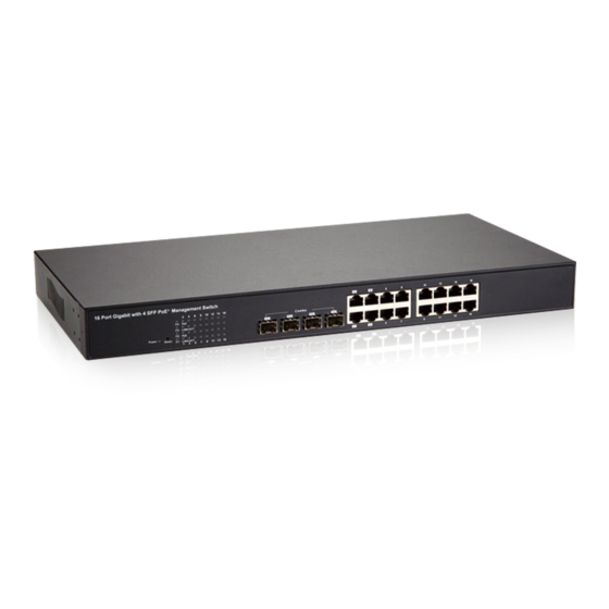
Introduction Product Overview This switch is a Web Management Switch equipped with 16-ports 10/100/1000BaseT(X) with 4-port gigabit SFP open slots. It was designed for easy installation and high performance in an environment where traffic is on the network and the number of users increases continuously. The compact rigid desktop size was specifically designed for small to medium workgroups. -
Page 6: Quality Of Service
Multiple Spanning Tree support ( IEEE std 802.1s ) IGMP, GARP, GMRP, and GVRP support Quality of Service Programmable multi-layer classifier with four QoS classes per port Strict priority or weighted round-robin forwarding with guaranteed bandwidth allocation Traffic class assignment based on port DSCP ( IPv4 &... -
Page 7: Specification
Specifications Standard IEEE 802.3 10BaseT IEEE 802.3u 100BaseTX IEEE 802.ab 1000BaseT IEEE 802.3z 1000BaseSX/LX IEEE 802.3x Flow Control IEEE 802.3 Auto Negotiation IEEE 802.3 Auto-MDI/MDI-X IEEE 802.1ad Provider Bridge ( Q in Q ) IEEE 802.1x Port-based Network Access Control IEEE 802.1Q VLAN Tagging IEEE 802.3ad Link Aggregation IEEE 802.1d Spanning tree protocol... -
Page 8: Package Contents
Package Contents Before you start to install this switch, please verify your package that contains the following items: One Switch One Power Cord One User Manual One pair Rack-mount kit + 8 Screws 4 ... -
Page 9: Hardware Description
Hardware Description This part primarily presents hardware of the web-smart switch, physical dimensions and functional overview would be described. Physical Dimensions/ Weight 45 × 440 × 330 mm (H × W × D) / 4.4KG Front Panel The front Panel of the web-smart Switch consists of 16 gigabit RJ-45 ports + 4 gigabit SFP open slot. -
Page 10: Rear Panel
Rear Panel The 3-pronged power plug is placed at the rear panel of the switch right side shown as below. Hardware Installation Set the switch on a large flat space with a power socket close by. The flat space should be clean, smooth, level and sturdy. Make sure there is enough clearance around the switch to allow attachment of cables, power cord and allow air circulation. -
Page 11: Software Description
Software Description This part instructs user how to set up and manage the switch through the web user interface. Please follow the description to understand the procedure. At the first, open the web browser, and go to 192.168.2.1 site then the user will see the login screen. -
Page 12: Configuration
After the user login, the right side of website shows all functions as Fig. 1-2. Figure 1-2 Configuration System System Configuration This page shows system configuration information. User can configure information as below: 8 ... - Page 13 Figure 2-1 MAC Address: Displays the unique hardware address assigned by manufacturer (default). S/W Version: Displays the switch’s firmware version. H/W Version: Displays the switch’s Hardware version. DHCP Enabled: Click the box to enable DHCP 9 ...
-
Page 14: Ports
Fallback IP address: Manually assign the IP address that the network is using. The default IP is 192.168.2.1 Fallback Subnet Mask: Assign the subnet mask to the IP address Fallback Gateway: Assign the network gateway for industrial switch. The default gateway is 0.0.0.0. Management VLAN: ID of a configured VLAN (1-4094) through which you can manage the switch. -
Page 15: Vlan
Power Saving Mode Adjusts the power provided to ports based on the length of the cable used to connect to other devices. Only sufficient power is used to maintain connection requirements. Mode: allow user to manually set the port speed such as Auto, 10 half, 10 Full, 100 Half, 100 Full, 1000 Full or Disabled. -
Page 16: Aggregation
Figure 2-3 Aggregation Port trunk allows multiple links to be bundled together and act as a single physical link for increased throughput. It provides load balancing, and redundancy of links in a switched inter-network. Actually, the link does not have an inherent total bandwidth equal to the sum of its component physical links. -
Page 17: Lacp
LACP IEEE 802.3ad Link Aggregation Control Protocol (LACP) increases bandwidth by automatically aggregating several physical links together as a logical trunk and providing load balancing and fault tolerance for uplink connections. LACP Port Configuration Port: The port number. Enabled: Enables LACP on the associated port. Key Value: Configures a port's LACP administration key. -
Page 18: Rstp
RSTP IEEE 802.1w Rapid Spanning tree protocol (LACP) provides a loop-free network and redundant links to the core network with rapid convergence to ensure faster recovery from failed links, enhancing overall network stability and reliability. RSTP System Configuration System Priority: This parameter configures the spanning tree priority globally for this switch. -
Page 19: 802.1X
RSTP Port Configuration Port: The port ID. It cannot be changed. Aggregations mean any configured trunk group. Enabled: Click on the tick-box to enable/disable the RSTP protocol for the port. Edge: Expect the port to be an edge port (linking to an end station) or a link to another STP device. - Page 20 and forward it to another remote RADIUS authentication server to verify access rights. The EAP packet from the RADIUS server also contain the authentication method to be used. The client can reject the authentication method and request another, depending on the configuration of the client software and the RADIUS server.
- Page 21 between hosts connected to the switch and multicast routers in the network. When a switch hears an IGMP report from a host for a given multicast group, the switch adds the host’s port number to the multicast list for that group. And, when the switch hears an IGMP Leave, it removes the host’s port from the table entry.
-
Page 22: Qos
Port to Mirror to: The port that will “duplicate” or “mirror” the traffic on the source port. Only incoming packets can be mirrored. Packets will be dropped when the available egress bandwidth is less than ingress bandwidth. Ports to Mirror: Select the ports that you want to mirror from this section of the page. - Page 23 Figure 2-9-1 QoS Mode: QoS Disabled When the QoS Mode is set to QoS Disabled, the following table is displayed. QoS Mode: 802.1p Packets are prioritized using the 802.1p field in the VLAN tag. This field is three bits long, representing the values 0 - 7. When the QoS Mode is set to 802.1p, the 802.1p Configuration table appears, allowing you to map each of the eight 802.1p values to a local priority queue (low, normal, medium or high).
- Page 24 QoS Mode: DSCP DSCP: Packets are prioritized using the DSCP (Differentiated Services Code Point) value. The Differentiated Services Code Point (DSCP) is a six-bit field that is contained within an IP (TCP or UDP) header. The six bits allow the DSCP field to take any value in the range 0 - 63.
-
Page 25: Filter
Figure 2-9-5 Filter Configuration There are 3 mode that you can choice for filter configuration: Disabled: this mode is protected from potential threats like hackers, if the traffic from illegal MAC addresses will not be forwarded by the switch. Static: This table displays the static MAC addresses connected, as well as the DHCP: Figure 2-10... -
Page 26: Power Over Ethernet
PoE (Power over Ethernet) Configuration PoE technology is a system to pass electrical power safely, along with data, on Ethernet cabling. Power is supplied in common mode over two or more of the differential pairs of wires found in the Ethernet cables and comes from a power supply within a PoE enabled networking devise such as Switch or can be injected into a cable run with a midspan power supply. -
Page 27: Rate Limit
Rate Limit Configuration Type of Port: You can define the certain port as Policer and Shaper before you set up the rate limit. No Limit: This drop-down menu allows you to specify that the selected port will have no bandwidth limit. Rate Limit: There is also allow you to enter the data rate, in Kbits per second, this can limit for the selected port. - Page 28 Figure 2-12-1 Enable Rate Limit: Click the check box to enable storm control. Rate (number of frames per second): The Rate field is set by a single drop-down list. The same threshold is applied to every port on the switch. When the threshold is exceeded, packets are dropped, irrespective of the flow-control settings.
-
Page 29: Statistic Overview
Monitorning Statistic Overview Statistic Overview for all ports User can mirror traffic from any source port to a target port for real-time analysis the following figures shows clearly the statistics overview. Figure 3-1 Detailed Statics To view the statistics of individual ports, click one of the linked port numbers for details. - Page 30 Figure 3-3-1 Port: The port number. Port Active: Shows if the port is a member of an active LACP group. Partner Port Number: A list of the ports attached at the remote end of this LAG link member. Operational Port Key: Current operational value of the key used by this LAG.
-
Page 31: Rstp Status
RSTP Status RSTP VLAN Bridge Overview Figure 3-4 Hello Time: Interval (in seconds) at which the root device transmits a configuration message. Max Age: The maximum time (in seconds) a device can wait without receiving a configuration message before attempting to reconfigure. All device ports (except for designated ports) should receive configuration messages at regular intervals. -
Page 32: Igmp Status
Root ID : The priority and MAC address of the device in the Spanning Tree that this switch has accepted as the root device, and the port connected to the root device. RSTP Port Status Port/Group: The number of a port or the ID of a static trunk. Path Cost: The cost for a packet to travel from this port to the root in the current Spanning Tree configuration. -
Page 33: Veriphy
Figure 3-5 VeriPHY VeriPHY Cable Diagnostics User can perform cable diagnostics for all ports or selected ports to diagnose any cable faults (short, open etc..) and feedback a distance to the fault. Cable Diagnostics: Cable diagnostics is performed on a per-port basis. Select the port number from the drop-down list. - Page 34 The following are some results of the ping command: Normal response: The normal response occurs in one to ten seconds, depending on network traffic. Destination does not respond: If the host does not respond, a “timeout” appears in ten seconds. Destination unreachable: The gateway for this destination indicates that the destination is unreachable.
-
Page 35: Maintenance
Figure 3-7-2 Figure 3-7-3 Maintenance Warm Restart Press Yes button to restart the switch, the reset will be complete when the power lights stop blinking. 31 ... -
Page 36: Factory Default
Figure 4-1 Factory Default Forces the switch to restore the original factory settings. To reset the switch, select “Reset to Factory Defaults” from the drop-down list and click Apply. The LAN IP Address, Subnet Mask and Gateway IP Address will be reset to their factory Figure 4-2 Software upload... -
Page 37: Logout
Figure43-4 Logout The administrator has write access for all parameters governing the onboard agent. User should therefore assign a new administrator password as soon as possible, and store it in a safe place. Figure 4-5 ... - Page 38 Reset button for the factory default setting Please take the following steps to reset the Web Smart Switch back to the original default: Step 1: Turn on the Web Smart Switch Step 2: Press and hold the reset button continuously for 5 seconds and release the reset button.
Need help?
Do you have a question about the ES-5816PHG and is the answer not in the manual?
Questions and answers