Table of Contents
Advertisement
Quick Links
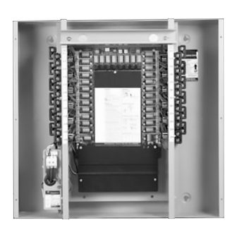
ProSys™ Lighting Control System Relay Panels
RINTER2424PSP 24-Relay Interior shown with RTUB24
DESCRIPTION
The ProSys Lighting Control System is a small network of
relay panels and occupant control switches linked by a 4-wire
dataline. Together, these devices form a reconfigurable
switching platform — one that uses "softwiring" instead of
hardwiring to link occupant switches to relays. Scheduling
capability can be readily added by simply mounting an
RCLK8PS Softwired Clock to the DIN rail in any relay panel.
The RINTERxxxxPS(P)
1
is the interior for a ProSys
Lighting Control System Relay Panel. The complete relay
panel assembly will include the following:
1. Tub (RTUBxx)
2. Interior (RINTERxxxxPS or RINTERxxxxPSP)
3. Power Supply (RPWRxxx)
4. Cover (RCOVxxxx)
These instructions do not cover all details or variations in equipment nor do they provide for every possible contingency that may be met in connection with
installation, operation or maintenance. Should further information be desired or should particular problems arise that are not covered for the purchaser's purposes,
the matter should be referred to the GE Company.
DEH40212 Installation Instructions
GE Total Lighting Control
ProSys Lighting Control System
Catalog Number RINTERxxxPS(P)
This instruction sheet will show you how to:
1. Install the Relay Panel(s)
2. Install and Test the Dataline
3. Document the Relay Panels
Full descriptions of the installation and operation of Softwired
Switches and the Softwired Clock and other optional
automation devices are located in other sections of this
manual and are provided with each hardware unit.
Before starting, read the following installation
instructions. If you have questions, call GE Total
Lighting Control Service at:
1-877-584-2685 (LTG-CNTL) in the USA and Canada.
1
Advertisement
Table of Contents

Related Manuals for GE ProSys DEH40212


Summary of Contents for GE ProSys DEH40212
- Page 1 These instructions do not cover all details or variations in equipment nor do they provide for every possible contingency that may be met in connection with installation, operation or maintenance. Should further information be desired or should particular problems arise that are not covered for the purchaser's purposes, the matter should be referred to the GE Company.
- Page 2 DEH40212 Installation Instructions CAUTION: Make sure all power is OFF before wiring. Do not energize wiring until the unit is fully assembled. Conform to all applicable codes. RELAY PANEL INSTALLATION SWITCHED LIGHTING CIRCUITS Figure 1 1.5" x 1.5" CROSSOVER WIRING CHANNEL (TOP AND BOTTOM) 2"...
- Page 3 DEH40212 Installation Instructions POWER UP AND TEST RELAYS 1. Apply power to the power supply only. As shown in LED INDICATOR Figure 3, to the right, press the Relay Control Button next Figure 3 to each relay’s yellow plug-in termination to toggle it ON/ OFF.
- Page 4 Note: To ensure good communications between panels, the installer must comply with the dataline specification. GE will not warrant a system using a dataline that does not meet our specification. To avoid questions, use GE RLONWIRE-4P (plenum rated). Do not run the dataline in conduit or wiring trays with power wires.
- Page 5 DEH40212 Installation Instructions HARDWIRE LOW-VOLTAGE SWITCHES (OPTIONAL) Each of the ProSys panel’s eight channels has a single switch input which will accept any of the dry-contact configurations Figure 7 – Hardwired Switch Configurations shown in Figures 6 and 7, and also provides status feedback RED/BLACK JUMPER for that channel.
- Page 6 DEH40212 Installation Instructions GE Total Lighting Control GE Total Lighting Control 41 Woodford Avenue, Plainville, CT 06062 ©2000 General Electric Company DEH40212 BL 0700 R02...
Need help?
Do you have a question about the ProSys DEH40212 and is the answer not in the manual?
Questions and answers