Table of Contents
Advertisement
OEM Manual
Caution for Safety
Read Safety descriptions carefully.
Read and recommend drive usage cautions to your end user.
Keep this manual with care.
K6602743
Rev.2
02.12.'02
DK23EB-40 Disk Drive
Specifications
REV.2
H I T A C H I
All Rights Reserved, Copyright
©
2001 Hitachi, Ltd.
- 1 -
(Total 112 pages)
Advertisement
Table of Contents

Related Manuals for Hitachi DK23EB - Travelstar Series 20 GB Hard Drive


Summary of Contents for Hitachi DK23EB - Travelstar Series 20 GB Hard Drive
-
Page 1: Specifications
Read Safety descriptions carefully. Read and recommend drive usage cautions to your end user. Keep this manual with care. (Total 112 pages) H I T A C H I © All Rights Reserved, Copyright 2001 Hitachi, Ltd. K6602743 Rev.2 02.12.’02 - 1 -... -
Page 2: To Use This Product Safely
Rev.0: 01.11.’02 Preliminary Rev.1: 02.01,’02 Rev.2: 02.12.’02 To use this product safely To use the product, read safety descriptions below and understand thoroughly. Keep this manual with care to insure unlimited use. General Caution for Safety The followings are general cautions for safe use of this product. (Caution before Product Use) - Please read and follow all instructions and cautions described on “Safety Instructions”... - Page 3 This product is sold with a limited warranty and specific remedies are available to the original purchaser in the event the product fails to conform to the limited warranty. Hitachi’s liability may be further limited in accordance with its sales contact.
-
Page 4: Safety Instructions
Safety Instructions Caution 1. The product is not authorized for use in life support devices or systems or other applications that pose a significant risk of personal injury. 2. Since the drive uses glass media for the disk platter, opening of Metal Head Disk Assembly (HDA) may cause bodily injury. - Page 5 Further Hitachi reserves the right to revise this publication and to make changes from time to time in the content hereof without obligation to notify any person of such revisions or changes.
-
Page 6: Table Of Contents
Contents Page --------------------------- To use this product safely 1. 0 General --------------------------- 1.1 General --------------------------- 1.2 General Caution --------------------------- 2.0 Components --------------------------- 3.0 Specification Summary --------------------------- 3.1 Principal Specifications --------------------------- 3.2 Environmental Specifications and Reliability --------------------------- 3.3 Drive Usage Condition Specifications --------------------------- 3.4 Load/Unload Specifications ---------------------------... - Page 7 6.3.2 Command --------------------------- 6.3.2.1 Command Summary --------------------------- 6.3.2.2 Command BSY Timing --------------------------- 6.3.2.3 PIO Data In Commands --------------------------- 6.3.2.3.1 Identify Device [ECh] --------------------------- 6.3.2.3.2 Read Buffer [E4h] --------------------------- 6.3.2.3.3 Read Sectors [20h, 21h] --------------------------- 6.3.2.3.4 Read Long [22h, 23h] --------------------------- 6.3.2.3.5 Read Multiple [C4h] --------------------------- 6.3.2.4 PIO Data Out Commands...
- Page 8 6.3.2.8.12 SMART Read Log Sector [B0h, Sub D5h] --------------------------- 6.3.2.8.13 SMART Write Log Sector [B0h, Sub D6h] --------------------------- 6.3.2.9 Security Mode Feature --------------------------- 6.3.2.9.1 Security Mode Default Setting --------------------------- 6.3.2.9.2 Initial Setting of the User Password --------------------------- 6.3.2.9.3 Security Mode Operation from Power-on or Hardware Reset ---------------------- 6.3.2.9.4 User Password Lost --------------------------- 6.3.2.9.5 Security Set Password [F1h]...
-
Page 9: General
1.0 General 1.1 Introduction The DK23EB series disk drives reach high capacities (40GB for 9.5mm height) in a 2.5 type form factor by applying the latest high-density recording technology. Capacity Model (Formatted) Height Interface DK23EB-40 40.007 GB 9.5 mm ATA-5(IDE) [Features] GMR Head ID-less Format... -
Page 10: General Caution
1.2 General Caution Caution Adhere to the following cautions. (a) Warranty void if Metal Head Disk Assembly (HDA) is opened, or any HDA seal/label is broken. (b) Hot swapping (Power on) damages the drive. The drive should be swapped during Power Off only. (c) Shock can result in permanent damage to the drive and/or loss of data. -
Page 11: Breather Hole
(Continued) (d) Do not cover the breather hole. If the hole was covered with any material, it shall result in permanent damage to the drive and/or loss of data. Label or seal shall be attached on the cover avoiding the breather hole. -
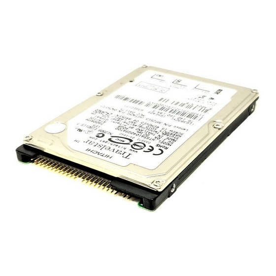
Page 12: Components
2.0 Components DK23EB-40 Disk Drive Figure 2-1 Overview of DK23EB-40 (9.5mm height) Note: 1) Prepare connection cables referring to Sec. 6.2. 2) Mounting holes are compatible with DK237A-XX, DK238A-XX, DK239A-XX, DK23AA-XX, DK23BA-xx, DK23BA-XXE,DK23CA-XX, DK23CA-XXF, DK23DA-XX and DK23DA-XXF. K6602743 Rev.2 02.12.’02 - 12 -... -
Page 13: Specification Summary
3.0 Specification Summary 3.1 Principal Specifications Table 3.1 Principal Specifications Specifications Item Units DK23EB-40 Capacity per drive (Formatted) 40.007 Capacity per sector Bytes Disks Heads Cylinders 32,081 Seek time Average 13 *1 (Nominal Maximum 24 *1 value) Minimum Average latency Disk rotational speed 5,400 Recording density... - Page 14 *1 :Average time of seek is calculated under the following condition. (Read/Write ratio: Read only) Average of 10,000 random seeks, Voltage 5.0V, Temperature 25°C. Maximum time of seek is calculated under the following condition. Average of 1,000 full stroke seeks, Voltage 5.0V, Temperature 25°C. This maximum time is not included the seek time by seek retry.
-
Page 15: Environmental Specifications And Reliability
3.2 Environmental Specifications and Reliability Table 3.2 Environmental Specification and Reliability Item Specification DK23EB-40 Operational Ambient *1 5 to 55°C temperature Non-operational -40 to 70°C *2 Temperature gradient Max. 20°C /hour Relative humidity Operational 5 to 90 % Non-operational 5 to 95 % Maximum wet Operational 29°C (without condensation) -
Page 16: Drive Usage Condition Specifications
*4 : 3.9 Bels are the maximum sound power levels with A-weighted. This value is specified at product shipment, except during power on, load, unload or power down. Clicking noise of magnet latch operation occurs at loading and unloading operation of the magnetic heads. Also, the clicking noise of the magnet latch occurs at emergency unloading operations. -
Page 17: Load/Unload Specifications
3.4 Load/Unload Specifications Load /Unload is a mechanism to load/unload the heads on the disk surfaces. 3.4.1 Normal Load/Unload Normal load/unload operations are limited to maximum 300,000 times during HDD life. The normal unload operation is performed by the following commands. Standby Standby Immediate Sleep... -
Page 18: Installation
4.0 Installation 4.1 Installation Direction The DK23EB-40 can be installed in the 6 directions as shown below. Figure 4-1 Installation K6602743 Rev.2 02.12.’02 - 18 -... -
Page 19: Mounting Hdd
4.2 Mounting HDD 4.2.1 Mounting HDD with screws Caution Mount the HDD with the screws according to the following instruction to optimize the performance. (a) Mount the HDD with M3 screws. Take care not to add any distorting force to the HDD when mounting. Using 4 screws holes, secure the HDD. -
Page 20: Single Hdd Test Condition
4.2.2 Single HDD Test Condition To optimize the performance, keep the following instructions. 1) For the Single HDD test, HDD should be placed on an ABS-sheet. HDD should be place with no movement by external force min. 0.39N for X axis and Y-axis directions. 2) Don’t place HDD on a soft sponge sheet or hard surface at HDD test. -
Page 21: Attention For Hdd Installation
4.2.3 Attention for HDD Installation (1) In case of steel plate installation on HDD cover side, the spacing between Caution HDD cover and steel plate should be kept more than 2 mm. If this spacing is not kept for the steel plate, it may affect Load/Unload mechanism. (2) The PCBA side of the drive should be covered with insulation sheet if the active metal of host system may contact to the PCBA of the drive. -
Page 22: Dimensions
4.4 Dimensions 4-M3 3.5mm min. full thread 10.24 ± 0.25 76.6 ± 0.25 14.0 ± 0.25 4-M3 3.0mm min. full thread 100±0.45 (Unit : mm) Figure 4-4 Dimensions (DK23EB-40) K6602743 Rev.2 02.12.’02 - 22 -... -
Page 23: Packing And Handling
(1) Pack the device in an ESD protective bag with desiccant. (2) Use the original Hitachi cardboard box and the cushioning materials or equivalent cushioning structures to surround the above bag. (3) Never stack or package drives next to each other with at the proper cushion material separating them. -
Page 24: Handling
5.2 Handling Mount the HDD with the screws according to the following instructions to optimize the Caution performance. It is necessary to prevent vibration, shock, and static electricity to the drive because it will damage the precision parts. In particular, prevent vibration or shock generated by dropping, knocking over, or hitting the drive. -
Page 25: Interface
6.0 Interface 6.1 Power Interface Only +5VDC power is applied to this Device. Figures 6-1 and 6-2 show power current transitions after turning on the power. Typical Spin-up Current Transition Current of +5V power Time (sec) Figure 6-1 Power Current Transition Typical Spin-up Current Transition with Retry Retry Current of... -
Page 26: Physical Interface
6.2 Physical Interface 6.2.1 Connector This device has a 2mm pitch interface connector which contains a power line. The connector location is shown in Figure 6-3. Table 6.1 Connector Parts List Name Parts number of recommended type Signal Connector Interface cable side Receptacle Molex 87259-4413 or equivalent Cable... -
Page 27: Connector Pin Assignment
6.2.2 Connector Pin Assignment Figure 6-4 Pin Assignments JUMPER0 JUMPER1 JUMPER2 JUMPER3 KEY(Removed) KEY(Removed) RESET- DD10 DD11 DD12 DD13 DD14 DD15 KEY(Removed) DMARQ DIOW- DIOR- IORDY CSEL DMACK- INTRQ IOCS16- PDIAG- CS0- CS1- DASP- GND(Motor) 5VDC(Logic) 5VDC(Motor) GND(Logic) Reserved K6602743 Rev.2 02.12.’02 - 27 -... -
Page 28: Description Of The Interface Signals
6.2.3 Description of the Interface Signals The interface is an ATA(IDE) interface. Reserved pins should be left unconnected. The signal names and the pin numbers are shown in Figure 6-4 and Table 6.2. Table 6.2 shows signal definitions. "I" of I/O type represents an input signal from the device and "O" represents an output signal from the device. - Page 29 Table 6.2 Signal List(2/3) Signal name I/O type Description INTRQ This is an interrupt signal for the host system. This signal is asserted by a selected device when the nIEN bit in the Device Control Register is "0". In other cases, this signal should be a high impedance state.
- Page 30 Table 6.2 Signal List(3/3) Signal name I/O type Description DASP- This signal indicates that a device is active or that Drive 1 is present when the power is turned on. Upon receipt of a command from the host, the device asserts this signal.
-
Page 31: Logical Interface
6.3 Logical Interface 6.3.1 I/O Registers Communication between the host system and the device is done through I/O registers. The Command Block Registers are used for sending commands to the device or posting device status. The Control Block Registers are used for controlling the device or posting device status. The registers are listed in Table 6.3. -
Page 32: Features Register
Name ICRC IDNF ABRT TK0NF AMNF a) AMNF(Address Mark Not Found): This bit indicates that a data address mark is not found after the correct ID field is detected. b) TK0NF(Track 0 Not Found): This bit indicates that Track 0 is not found during the execution of the Recalibrate command. -
Page 33: Device/Head Register
6.3.1.8 Device/Head Register This register has the binary coded address of device and head selected. The head numbers begins with "0". Name a) Bits HS3 to HS0 are head addresses to be selected. HS3 is the highest bit. The address of the currently selected head is displayed in this register when a command is completed. -
Page 34: Alternate Status Register
6.3.1.11 Alternate Status Register The information in this register is a duplicate of that in the Status Register. Reading this register will not clear the interrupt. 6.3.1.12 Device Control Register This register includes the software reset bit and the interrupt enable bit. Name SRST nIEN... -
Page 35: Command
6.3.2 Commands 6.3.2.1 Command Summary Commands are issued to the device first loading the Command Block Registers with any information needed for the command. Then a command code is written to the Command Register, which starts the execution of the command. Table 6.4 Command Codes Command Description Protoc... -
Page 36: Command Bsy Timing
Table 6.4 Command Codes (Continued) Command Description Protoc Clas Code Parameter Setup SMART Commands SMART Enable/Disable Auto Save SMART Save Attribute Values SMART Enable Operations SMART Disable Operations SMART Return Status SMART Enable/Disable Automatic Off-line SMART Execute Off-line Immediate SMART Read Log Sector SMART Write Log Sector Security Commands Security Disable Password... -
Page 37: Pio Data In Commands
6.3.2.2 Command BSY Timing The manner in which a command is accepted varies by the three classes of command acceptance all predicated on the fact that to receive a command, BSY=0. The following describes by the conditions under which busy is set after receipt of a command. Class1 - The device sets busy within 400 ns. -
Page 38: Identify Device [Ech]
6.3.2.3.1 Identify Device [ECh] The Identify Device command enables the host to receive parameter information from the device. When the command is issued, the device sets BSY, stores the required parameter information in the sector buffer, sets DRQ, and generates an interrupt. The host then reads the information from the sector buffer through the Data Register. - Page 39 Table 6.5 Identify Device Information ( Continued) Word Description Value (HEX.) Capabilities 4000h Bit 15 0 (fixed) Bit 14 1 (fixed) Bit 13 - 1 0 = Reserved Bit 0 1 = Standby timer value is equal to or greater than 5 minutes.
- Page 40 Table 6.5 Identify Device Information ( Continued) Word Description Value (HEX.) ATA Interface Major Version Number 003Ch Bit 15 - 6 Reserved for ATA-6 - 14 Bit 5 1 = Supports ATA-5 Bit 4 1 = Supports ATA-4 Bit 3 1 = Supports ATA-3 Bit 2 1 = Supports ATA-2...
- Page 41 Table 6.5 Identify Device Information ( Continued) Word Description Value (HEX.) Command set/feature supported extension 4003h 0000h or FFFFh = Command set notification not supported Bit 15 0 (fixed) Bit 14 1 (fixed) Bit 13 - 2 0 = Reserved Bit 1 1 = SMART Self-test supported Bit 0...
- Page 42 Table 6.5 Identify Device Information ( Continued) Word Description Value (HEX.) Command set/feature enabled 1808h 0000h or FFFFh = Command set notification not supported Bit 15 –14 0 = Reserved Bit 13 1 = Flush cache EXT command supported Bit 12 1 = Flush Cache command supported Bit 11 1 = Device Configuration Overlay supported...
- Page 43 Table 6.5 Identify Device Information ( Continued) Word Description Value (HEX.) Current advanced power management level value 40XXh Word 91 contains the current Advanced Power Management level settings. Master password revision code XXXXh Word 92 contains the value of the Master password revision code set when the Master Password was last changed.
- Page 44 Table 6.5 Identify Device Information( Continued) Word Description Value (HEX.) Removable Media Status Notification feature set support 0000h Bit 15 – 2 0 = Reserved Bit 1 – 0 00 = Removable Media Status Notification feature set not support 01 = Removable Media Status Notification feature supported 10 = Reserved 11 = Reserved...
-
Page 45: Read Buffer [E4H]
6.3.2.3.2 Read Buffer [E4h] The Read Buffer command enables the host to read the current contents of the device's sector buffer. When this command is issued, the device sets BSY, sets up the sector buffer for a read operation, sets DRQ, clears BSY, and generates an interrupt. The host then reads up to 512 bytes of data from the sector buffer. -
Page 46: Pio Data Out Commands
6.3.2.4 PIO Data Out Commands Execution includes the transfer of one or more 512-byte sectors of data from the host to the device. 1) The host writes any required parameters to the Features, Sector Count, Sector Number, Cylinder Low, Cylinder High, and Device/Head Registers. 2) The host writes the command code to the Command Register. -
Page 47: Format Track [50H]
Multiple Mode command, which must be executed prior to the Write Multiple command, sets the block count of sectors to be transferred. When the Write Multiple command is issued, the Sector count Register contains the number of sectors (not the number of blocks or the block count) requested. If the number of requested sector is not evenly divisible by the block count, as many full blocks as possible are transferred, followed by a final, partial block transfer. -
Page 48: Read Verify [40H, 41H]
6.3.2.5.2 Read Verify [40h, 41h] This command is same as the Read Sectors command, except that DRQ is never set and no data is transferred to the host. When the requested sectors have been verified, the device clears BSY and generates an interrupt. -
Page 49: Set Multiple Mode [C6H]
Table 6.8 Transfer mode code definition Transfer Mode Multi-Word DMA Mode (X: 0, 1, 2): Mode 0: 4.1 MB/sec Mode 1: 13.3 MB/sec Mode 2: 16.6 MB/sec Ultra DMA Mode (X: 0, 1, 2, 3, 4, 5): Mode 0: 16.6 MB/sec Mode 1: 25.0 MB/sec Mode 2: 33.3 MB/sec Mode 3: 44.4 MB/sec... -
Page 50: Flush Cache [E7H]
6.3.2.5.8 Flush Cache [E7h] The Flush Cache command is to check the device if write cache data were written on the disk or not. BSY is set until all write cache data are written on the disk or a write error is occurred. Maximum time to write the cache data on the disk is 30 seconds. -
Page 51: Power Commands
6.3.2.6 Power Commands 6.3.2.6.1 Power Management Supported commands and functions: Idle command Idle Immediate command Sleep command Standby command Standby Immediate command Advanced Power management(APM)* Standby timer (1) Low power consumption modes The drive supports the following low power consumption modes. Active mode : The spindle motor is rotated. -
Page 52: Advanced Power Management
(3) Standby Timer Standby timer is provided for automatic power saving control. The device automatically moves to the Standby mode if the host does not issue a command within the timer period. The Standby timer is disabled at power-on. The Standby timer value is changeable using Idle and Standby commands. The timer can be set up to 30 minutes. -
Page 53: Check Power Mode [98H, E5H]
(2) Active Idle Mode/Low Power Idle Mode The device supports two kind of sub-Idle modes called Active Idle mode and Low Power Idle mode. Selecting the APM mode, the power consumption can be reduced. Active Idle mode: Heads are loaded, and kept on outer cylinder. Low Power Idle mode: Heads are unloaded outside of the disk platters and the spindle motor is rotating. -
Page 54: Idle [97H, E3H]
6.3.2.6.4 Idle [97h, E3h] This command causes the device to enter to the Idle Mode. The Sector Count Register sets the standby timer value. By the power on default, the Standby timer is disabled. Sector Count Value Standby Timer Value SC = 0 Disabled 0 <... -
Page 55: Dma Data In/Out Commands
6.3.2.7 DMA Data In/Out Commands The Read DMA and Write DMA commands execute data transfer using the slave-DMA channel. The host is required to enable the slave-DMA feature, if using these commands. 1) The host initializes the slave-DMA feature, if using these commands. 2) The host write any required parameters to the Features, Sector Count, Sector Number, Cylinder low, Cylinder High, and Device/Head registers. -
Page 56: Smart Feature
6.3.2.8 SMART Feature The intent of self-monitoring, analysis, and reporting technology (SMART) is to protect user data and minimize the likelihood of unscheduled system downtime that may be caused by predictable degradation and/or fault of the device. By monitoring and storing critical performance and calibration parameters, SMART devices attempt to predict the likelihood of near-term degradation or fault condition. -
Page 57: Smart Device Error Log Reporting
6.3.2.8.2 SMART Device Error Log Reporting The intent of SMART Device Error Log Reporting feature is to augment the SMART feature set to provide additional diagnostic information on device that have generated error conditions. The device retains a specified amount of previously executed commands, and write this data along with the time of a triggered error condition to the existing SMART Read Logging Sectors. -
Page 58: Smart Disable Operations [B0H, Sub D9H]
The SMART Enable Operations command enables access to all SMART capabilities within the device. Prior to receipt of this command attribute values are neither monitored nor saved by the device. The device will preserve the state of SMART (either enabled or disabled) across power cycles. Once enabled, the receipt of subsequent SMART Enable Operations commands shall not affect any of the attribute values. -
Page 59: Smart Return Status [B0H, Sub Dah]
6.3.2.8.7 SMART Return Status [B0h, Sub DAh] Task File Registers Command Cylinder High Cylinder Low Device/Head Sector Number Sector Count Features DRV : Device selection bit 0 : DRV0 1:DRV1 The SMART Return Status command is used to communicate the reliability status of the device to the host at the host’s request. -
Page 60: Smart Save Attribute Values [B0H, Sub D3H]
The state of the attribute AUTOSAVE feature (either enable or disable) will be preserved by the device across power cycles. A value of zero written by the host into the Sector Count register before issuing this command will cause this feature to be disabled. -
Page 61: Smart Enable/Disable Automatic Off-Line [B0H, Sub Dbh]
6.3.2.8.10 SMART Enable/Disable Automatic Off-line [B0h, Sub DBh] Task File Registers Command Cylinder High Cylinder Low Device/Head Sector Number Sector Count 00h:Disable F8h:Enable Features DRV : Device selection bit 0 : DRV0 1:DRV1 SMART Enable/Disable Automatic Off-line command enables and disables the Automatic Off-line feature. If Automatic Off-line is enabled, the device automatically correct attribute data in an off-line mode periodically and save the attribute data on the disk. -
Page 62: Smart Execute Off-Line Immediate [B0H, Sub D4H]
6.3.2.8.11 SMART Execute Off-line Immediate [B0h, Sub D4h] Task File Registers Command Cylinder High Cylinder Low Device/Head Sector Number Sector Count Features DRV : Device selection bit 0 : DRV0 1:DRV1 This command causes the device to immediately initiate the optional set of off-line data collection activities that collect attribute data in an off-line mode and then save this data to the device, or execute a self- diagnostic test routine in either captive or off-line mode. - Page 63 (1) Off-line mode The following describes the protocol for executing a SMART EXECUTE OFF-LINE IMMEDIATE subcommand routine (including a self-test routine) in the off-line mode. a) The device executes command completion before executing the subcommand routine. b) After clearing BSY to zero and setting DRDY to one after receiving the command, the device does not set BSY nor clears DRDY during execution of the subcommand routine.
- Page 64 (2) Captive mode When executing a self-test in captive mode, the device sets BSY to one and executes the self-test routine after receipt of the command. At the end of the routine the device places the results of this routine in the Self-test execution status byte and executes command completion.
-
Page 65: Smart Read Log Sector [B0H, Sub D5H]
6.3.2.8.12 SMART Read Log Sector [B0h, Sub D5h] Task File Registers Command Cylinder High Cylinder Low Device/Head Sector Number Log Address Sector Count Number of sector to be read Features DRV : Device selection bit 0 : DRV0 1:DRV1 SMART Read Log Sector command returns the indicated log to the host. Sector number - Indicates the log to be returned as described in following table . - Page 66 (2) SMART Error Log Sector [Log Sector Address = 01h] The following table defines the 512 bytes that make up the SMART error log sector. Error log data structures includes UNC errors, IDNF errors for which the address requested was valid, servo errors, write fault errors, etc.
- Page 67 Table 6.14 Error log data structure Byte Descriptions n thru n+11 First command data structure n+12 thru n+23 Second command data structure n+24 thru n+35 Third command data structure n+36 thru n+47 Fourth command data structure n+48 thru n+59 Fifth command data structure n+60 thru n+89 Error data structure Command data structure...
- Page 68 Error data structure The error data structure contains the error description of the command for which an error was reported as described in following. Table 6.15 Error data structure Byte Descriptions Reserved Content of the Error register after command completion occurred. Content of the Sector Count register after command completion occurred.
- Page 69 (3) SMART Self-test Log Sector [Log Sector Address = 06h] Following Table defines the 512 bytes that make up the SMART self-test log sector. Byte Descriptions 0 - 1 Self-test log data structure revision number The value of Self-test log data structure revision number is 0001h 2 - 25 descriptor entry 26 - 49...
-
Page 70: Smart Write Log Sector [B0H, Sub D6H]
6.3.2.8.13 SMART Write Log Sector [B0h, Sub D6h] Task File Registers Command Cylinder High Cylinder Low Device/Head Sector Number Log Address Sector Count Number of sector to be written Features DRV : Device selection bit 0 : DRV0 1:DRV1 SMART Write Log Sector Command writes an indicated number of 512 byte data sector to the indicated log sector. -
Page 71: Security Mode Feature
6.3.2.9. Security Mode Feature The Security Mode feature set is a password system that restricts access to user data stored on a device. The system has two passwords, User and Master and two security levels, High and Maximum. The security system is enabled by sending a user password to the device with the Security Set Password command. -
Page 72: Initial Setting Of The User Password
6.3.2.9.2 Initial Setting of the User Password When a user password is set, the device shall automatically enter lock mode the next time the device is powered-on or hardware reset. 6.3.2.9.3 Security Mode Operation from Power-on or Hardware Reset When lock is enabled, the device reject media access commands until a Security Unlock command is successfully completed. -
Page 73: User Password Lost
6.3.2.9.4 User Password Lost If the user password is lost and High level security is set, the device shall not allow the user to access data. The device shall be unlocked using the master password. If the user password is lost and Maximum security level is set, data access shall be impossible. However, the device shall be unlocked using the SECURITY ERASE UNIT command with the master password to unlock the device and shall erase all user data. -
Page 74: Security Set Password [F1H]
6.3.2.9.5 Security Set Password [F1h] This command requests a transfer of a single sector of data from the host. The following table defines the content of this sector of information. The data transferred controls the function of this command. The revision code field is returned in the Identify Device word 92. The valid revision codes are 0000h to FFFDh. -
Page 75: Security Unlock [F2H]
6.3.2.9.6 Security Unlock [F2h] This command requests a transfer of a single sector of data from the host. The following table defines the content of this sector of information. Word Contents Control Word Bit 15-1 Reserved Bit 0 Identifier 0 = Compare user password 1 = Compare master password 1-16 Password(32bytes) -
Page 76: Security Erase Prepare [F3H]
6.3.2.9.7 Security Erase Prepare [F3h] The Security Erase Prepare command shall be issued immediately before the Security Erase Unit command to enable device erasing and unlocking. This command is to prevent accidental erasure of the device. Device returns Aborted command error if the device is in Frozen mode. 6.3.2.9.8 Security Erase Unit [F4h] This command requests a transfer of a single sector of data from the host. -
Page 77: Security Freeze Lock [F5H]
6.3.2.9.9 Security Freeze Lock [F5h] The Security Freeze Lock command sets the device to frozen mode. After this command is completed any other commands which update the device lock functions are rejected. Frozen mode is quit by power off or hardware reset. -
Page 78: Security Mode Command Action [F1H]
6.3.2.9.11 Security Mode Command Action The following table defines executable commands in each lock mode state. Command Locked mode Unlocked mode Frozen mode Execute Device Diagnostics Executable Executable Executable Format Track Aborted Executable Executable Flush Cache Aborted Executable Executable Identify Device Executable Executable Executable... -
Page 79: Protected Area Feature, Address Offset Feature
6.3.2.10 Protected Area Feature, Address Offset Feature 6.3.2.10.1 Protected Area Feature and Set Max Security Extension A reserved area for data storage outside the normal operating system is required for several specialized applications. Systems may wish to store configuration data or save memory to disk data in a location that operation system can not change. -
Page 80: Address Offset Feature
The Set Max Unlock command changes the device from the Set Max Locked mode to the Set Max Unlocked mode. The Set Max Freeze Lock command allows the host to disable the Set Max commands (including Set Max Unlock) until the next power cycle. When this command is accepted the device is in the Set Max Frozen mode. - Page 81 Before Enable Address Offset Mode A reserved area has been created using a non-volatile Set Max Address Command. User Accessible Area Reserved Area LBA 0 LBA R LBA M After Enable Address Offset Mode The former reserved area is now the user accessible area. The former user accessible area is now the reserved area.
-
Page 82: Read Max Address Command [F8H]
6.3.2.10.3 Read Max Address Command [F8h] This command returns the native maximum LBA/cylinders of the device which is not affect by Set Max Address Command. The data returned in the command block registers is the maximum device size as shown in the following tables. - CHS Mode Task File Registers Cylinder High... -
Page 83: Set Max Address Command [F9H, Sub 00H]
6.3.2.10.4 Set Max Address Command [F9h, Sub 00h] The Set Max Address Command overwrites the maximum LBA/cylinder of the device in a range of actual device capacity. Once the device receives this command, all accesses beyond that LBA/cylinder are rejected. Identify device command returns the LBA/Cylinder, which is set via this command as default. - Page 84 The data returned in the command block registers is the maximum device size as shown in the following tables. - CHS Mode Maximum sector number and maximum head number are fixed values, and the values are 16 and 63. Task File Registers Cylinder High Maximum Cylinder High Cylinder Low...
-
Page 85: Set Max Set Password Command [F9H, Sub 01H]
6.3.2.10.5 Set Max Set Password Command [F9h, Sub 01h] This command requests a transfer of a single sector of data from the host. Table 6.17 defines the content of this sector of information. The password is retained by the device until the next power cycle. When the device accepts this command the device is in Set Max Unlocked state. -
Page 86: Set Max Unlock Command [F9H, Sub 03H]
6.3.2.10.7 Set Max Unlock Command [F9h, Sub 03h] This command requests a transfer of a single sector of data from the host. Table 6.17 defines the content of this sector of information. The password supplied in the sector of data transferred shall be compared with the stored Set Max password. -
Page 87: Device Configuration Overlay Feature
6.3.2.11 Device Configuration Overlay Feature The Device Configuration Overlay feature set allows a utility program to modify some of the commands, modes, and features sets that a device reports as supported in the IDENTIFY DEVICE command response as well as the capacity reported. Commands unique to the Device Configuration Overlay feature set use a single command code and are differentiated from one another by the value placed in the Features register. -
Page 88: Device Configuration Restore [B1H, Sub 00H]
6.3.2.11.1 Device Configuration Restore [B1h, Sub 00h] Task File Registers Command Cylinder High Cylinder Low Device/Head Sector Number Sector Count Features DRV : Device selection bit 0 : DRV0 1:DRV1 The DEVICE CONFIGURATION RESTORE command disables any setting previously made by a DEVICE CONFIGURATION SET command and returns the content of the IDENTIFY DEVICE command response to the original settings as indicated by the data returned from the execution of a DEVICE CONFIGURATION IDENTIFY command. -
Page 89: Device Configuration Identify [B1H, Sub 02H]
6.3.2.11.3 Device Configuration Identify [B1h, Sub 02h] Task File Registers Command Cylinder High Cylinder Low Device/Head Sector Number Sector Count Features DRV : Device selection bit 0 : DRV0 1:DRV1 The DEVICE CONFIGURATION IDENTIFY command returns a 512 byte data structure via PIO data-in transfer. - Page 90 Table 6.18 Device Configuration Identify Data Structure (continued) Word Description Value (HEX.) 3 - 6 Maximum LBA Address DK23EB-40: 4A8 52FFh Words 4 - 7 define the maximum LBA address. This is the highest address accepted by the device in the factory default condition.
-
Page 91: Device Configuration Set [B1H, Sub 03H]
6.3.2.11.4 Device Configuration Set [B1h, Sub 03h] Task File Registers Command Cylinder High Cylinder Low Device/Head Sector Number Sector Count Features DRV : Device selection bit 0 : DRV0 1:DRV1 The DEVICE CONFIGURATION SET command allows a device manufacturer or a personal computer system manufacturer to reduce the set of optional commands, modes, or feature sets supported by a device as indicated by a DEVICE CONFIGURATION IDENTIFY command. - Page 92 Table 6.19 Device Configuration Set Command Data Structure (Continued) Word Description Ultra DMA modes supported bit 15 - 6 0 = Reserved bit 5 1 = Ultra DMA mode 5 and below are supported Bit 5 is cleared to select no support for Ultra DMA mode 5. This bit shall not be cleared if Ultra DMA mode 5 is currently selected.
- Page 93 Table 6.19 Device Configuration Set Command Data Structure (Continued) Word Description Command Set / Feature Set Supported bit 15 - 9 0 = Reserved bit 8 1= 48-bit Addressing feature set supported Bit 8 is cleared to select no support for 48-bit Addressing feature set (DK23E series does not support 48-bit Addressing feature).
- Page 94 Table 6.19 Device Configuration Set Command Data Structure (Continued) Word Description Integrity word bit 15 - 8 Checksum The checksum shall be the two’s complement of the sum of all byte in words 0 through 254 and the byte consisting of bits 7:0 of word 255. Each byte shall be added with unsigned arithmetic, and overflow shall be ignored.
-
Page 95: Note For Write Cache And Auto Reallocation
6.3.2.12 Note For Write Cache and Auto Reallocation (1) Loss of data in write cache Write cache is a performance enhancement whereby the device reports as completion the write commands to the host as soon as the device has received all of the data into its cache buffer memory. This means that there is a possibility that power off even after write command completion might cause the loss of the data that the device has not written onto the media. -
Page 96: Interface Signal Timing
6.4 Interface Signal Timing 6.4.1 Data Transfer Timing Figures 6-4, 6-5, and 6-7 show the timing for asserting interface signals for transferring 16-bit and 8-bit data. Figure 6-4 PIO Data Transfer Timing(Mode 4) Addr Valid *1 DIOR-/DIOW- Write Data Valid *2 Read Data Valid *2 IOCS16- *1 Device Address consists of signals CS0-, CS1-, and DA2-0... - Page 97 Figure 6-5 IORDY Timing Read Data Valid DIOR-/DIOW- IORDY SYMBOL Description MIN(ns) MAX(ns) IORDY Setup Time IORDY Pulse Width 1250 Read Data Valid to IORDY active IORDY assertion to release Figure 6-7 Multi-word DMA Data Transfer Timing(Mode 2) CS0-/CS1- DMARQ DMACK- DIOR-/DIOW- Write Data Valid *3...
- Page 98 DIOR- Data Setup DIOW- Data Setup DIOW- Data Hold DMACK to DIOR- / DIOW- Setup DIOR- / DIOW- to DMACK Hold DIOR- / DIOW- Negated Pulse Width DIOR- / DIOW- to DMARQ Delay CS(1:0) valid to DIOR-/DIOW- CS(1:0) hold DMACK- to tristate K6602743 Rev.2 02.12.’02...
-
Page 99: Ultra Dma Data Transfer Timing
6.4.2 Ultra DMA Data Transfer Timing Figures 6-8 through 6-12 and 6-13 through 17 define the timings associated with all phases of Ultra DMA data transfer. Figure 6-8 Initiating an Ultra DMA Read D M AR Q (device) D M AC K- (host) ST O P (host) - Page 100 Figure 6-9 Sustained Ultra DMA Read Data 2CYC 2CYC DSTROBE at device DVHIC DVHIC DVSIC DVSIC DVHIC DD(15:0) at device DSTROBE at host DSIC DHIC DHIC DHIC DSIC DD(15:0) at host Note: DD(15:0) and DSTROBE signals are shown at both the host and the device to emphasize that cable settling time as well as cable propagation delay shall not allow the data signals to be considered stable at the host until some time after they are driven by the device.
- Page 101 Figure 6-10 Host pausing an Ultra DMA Read DMARQ (device) DMACK- (host) STOP (host) HDMARDY- (host) DSTROBE (device) DD(15:0) (device) Note: The host asserts STOP to request termination of the Ultra DMA burst no sooner than t after HDMARDY- is negated. Mode 0(ns) Mode 1(ns) Mode 2(ns) Mode3(ns) Mode4(ns) Mode5(ns) Description...
- Page 102 Figure 6-11 Device terminating an Ultra DMA Read DMARQ (device) DMACK- (host) STOP (host) HDMARDY- (host) IORDYZ DSTROBE (device) DD(15:0) DA0, DA1, DA2, CS0-, CS1- Note: The definitions for the STOP, HDMARDY and DSTROBE signal lines are no longer in effect after DMARQ and DMACK are negated.
- Page 103 Figure 6-12 Host terminating an Ultra DMA Read D M A R Q (device) M LI D M A C K - Z A H (host) A C K S T O P (host) A C K H D M A R D Y- (host) R F S M LI...
- Page 104 Figure 6-13 Initiating an Ultra DMA Write DMARQ (device) DMACK- (host) STOP (host) ZIORDY DDMARDY- (device) HSTROBE (host) DZFS DD(15:0) (host) DA0, DA1, DA2, CS0-, CS1- Note: The definitions for the STOP, DDMARDY and HSTROBE signal lines are not in effect until DMARQ and DMACK are asserted.
- Page 105 Figure 6-14 Sustained Ultra DMA Write Data 2CYC 2CYC HSTROBE at host DVHIC DVHIC DVHIC DVSIC DVSIC DD(15:0) at host HSTROBE at device DSIC DSIC DHIC DHIC DHIC DD(15:0) at device Note: DD(15:0) and HSTROBE signals are shown at both the device and the host to emphasize that cable settling time as well as cable propagation delay shall not allow the data signals to be considered stable at the device until some time after they are driven by the host.
- Page 106 Figure 6-15 Device pausing an Ultra DMA Write DMARQ (device) DMACK- (host) STOP (host) DDMARDY- (device) HSTROBE (host) DD(15:0) (host) Note: The device negates DMARQ to request termination of the Ultra DMA burst no sooner than t after DDMARDY- is negated. Mode 0(ns) Mode 1(ns) Mode 2(ns) Mode 3(ns) Mode 4(ns) Mde5(ns) Description SYMBOL MIN MAX MIN MAX MIN MAX MIN MAX MIN MAX MIN MAX...
- Page 107 Figure 6-16 Host terminating an Ultra DMA Write DMARQ (device) DMACK- (host) STOP (host) IORDYZ DDMARDY- (device) HSTROBE (host) DD(15:0) (host) DA0, DA1, DA2, CS0-, CS1- Note: The definitions for the STOP, DDMARDY and HSTROBE signal lines are no longer in effect after DMARQ and DMACK are negated.
- Page 108 Figure 6-17 Device terminating an Ultra DMA Write DMARQ (device) DMACK- (host) STOP (host) IORDYZ DDMARDY- (device) HSTROBE (host) DD(15:0) (host) DA0, DA1, DA2, CS0-, CS1- Note: The definitions for the STOP, DDMARDY and HSTROBE signal lines are no longer in effect after DMARQ and DMACK are negated.
-
Page 109: Power On And Hardware Reset Timing
6.4.3 Power On and Hardware Reset Timing Figure 6-18 Power On and Hardware Reset Timing RESET- BSY bit DRDY DRV 0 PDIAG- (device 0) (out) DASP- (out) DASP- (in) BSY bit DRDY DRV 1 (device 1) PDIAG- (out) DASP- (out) SYMBOL Description Units... -
Page 110: Glossary
< Glossary > AT Attachment ABRT Aborted Command AMNF AM Not Found Advanced Power Management BIOS Basic Input-Output System Bit Per Inch Busy Constant Density Recording Cylinder Head Sector CORR Corrected Data Cyclic Redundancy Check Contact Start/Stop Cylinder Direct Memory Accessing Drive DRDY Drive Ready... -
Page 111: Reference
<Reference> Factory Packaging The structure of the factory packaging is described in this reference. (1) Packaging Components Name Materials Quantity Package box Card box HDD Cushion Card Board Upper Cushion Card Board Side Cushion . Card Board Desiccant Silicagel Vinyl Package ESD protective bags (2) Standard Identification Label The label is indicated on the exterior of the package. - Page 112 Inner Box Partition Side Cushion (x4) (Outer Dimension of Inner Box) (Outer Dimension of Cardboard Box) Top Cushion Bottom Cushion (Unit: mm) K6602743 Rev.2 02.12.’02 - 112 -...
Need help?
Do you have a question about the DK23EB - Travelstar Series 20 GB Hard Drive and is the answer not in the manual?
Questions and answers