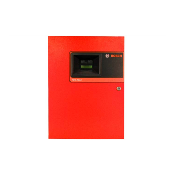
Bosch FPD-7024 Operating Instructions
V1.03 fire alarm control panel
Hide thumbs
Also See for FPD-7024:
- Operation and installation manual (102 pages) ,
- Operating instructions (2 pages) ,
- Operating instructions (2 pages)
Advertisement
Quick Links
Operating Instructions
FPD7024 (v1.03)
Understanding the Built-in Keypad
The keypad built into the control panel is an alphanumeric LCD keypad. It
has a two-line by 16-character display that provides information on various
control panel functions. In most instances, the top line of the display
provides general system status information, while the second line
describes specific devices that might be relevant to the current system
status. When keys are pressed, the display shows the current action on
the top line, while showing rotating menu choices on the second line. A
built-in sounder is used to annunciate keystroke entries and as an
interior warning device.
Modes of System Operation
The green Power LED lights when AC power is present,
and flashes when the unit is operating from battery power.
The red Alarm LED lights whenever the system has
registered an alarm and is not reset.
The yellow Supervisory LED lights whenever the system
registers a supervisory condition. It remains lit, even
when the supervisory sounder is silenced.
Scroll keys
are used to move through the
off-normal events indicated on the display.
The Disable key allows the system to disable or re-enable
inputs, notification appliance circuits or relays (outputs),
and the dialer.
The Test key allows one of seven special test modes to
be selected.
While programming, the Clear key can be used to exit
menus or exit programming mode entirely.
The Programming key selects the programming mode.
Normal Operation: When the system is operating normally,
LED is lit, and no other LEDs are lit. If the system is programmed to require a PIN,
LCD screen. Otherwise, the control panel bypasses this display and shows the date and time.
Alarm/Trouble/Supervisory Operation: When an alarm occurs, the built-in sounder turns on with a steady tone and outputs
programmed to activate with the current alarm condition(s) activate. The alarm display overrides any other system display. When a
trouble condition occurs (such as wiring for a point is cut, AC power fails, and so on), the sounder activates briefly, every 10 seconds
and the Trouble LED lights. When a supervisory condition occurs the sounder activates briefly, every 10 seconds and the
Supervisory LED lights.
Keypad Display during Alarm/Trouble/Supervisory Operation: In each case, the top line of the display shows
where xxx is the event number, yyy is the total number of events, zzz is the point number, and TTT is the event type (ALM
PTzzz
for Alarm, TRB for Trouble, or SUP for Supervisory). The second line of the display shows
programmed description for the affected point
When the Acknowledge key is pressed, the keypad and control panel peizo will silence but the NACs will not be affected. Pressing
the ◄ or the ► key allows stepping through the groups of off-normal conditions. Pressing the ▲ or the ▼key allows you to view
details of an off-normal condition within the group selected.
Using PIN Numbers: On systems configured with no requirement for PIN numbers, commands such as Reset and Silence are
performed by pressing the appropriate key once the panel is opened to access the keys. For systems requiring a PIN number, first
enter the user's assigned four-digit PIN number. Once the list of available options appears, simply press the key for the desired
command.
Fire Alarm Control Panel FPD-7024
Power
Trouble
Silenced
Alarm
Supervisory
Gnd Flt
1
2
3
Drill
Acknowledge
4
5
6
Disable
Silence
7
8
9
Test
0
#
Reset
*
History
Clear
Prog
Cmnd
SYSTEM NORMAL
This document must be framed and mounted
in view adjacent to the FACP.
The yellow Trouble LED lights whenever the system has
detected a problem with its wiring or internal circuitry. It
turns off only when the underlying trouble condition is
corrected. The trouble LED flashes while programming
mode is active.
The yellow Silenced LED lights when an alarm condition
is manually silenced by the user. It turns off when the
condition that was silenced is corrected.
The yellow Gnd Flt LED lights whenever a ground fault is
present on the system.
The Drill key is used to activate the local notification
appliance circuits manually.
Use the Acknowledge key to silence local keypad
sounders.
The Silence key mutes the bells/sirens for an alarm
condition.
The Reset key briefly turns off power to detectors to reset
them and clears any off-normal conditions.
The History key allows the record of system events to be
viewed.
The Command key is used to accept data when in
Programming mode.
appears on the top line of the display, the Power
: appears on the second line of the
ENTER PIN
◄GRP ▲VIEW GRP►
xxx/yyy TTT :
, alternating with the
Advertisement

Summary of Contents for Bosch FPD-7024
-
Page 1: Operating Instructions
Fire Alarm Control Panel FPD-7024 Operating Instructions FPD7024 (v1.03) Understanding the Built-in Keypad This document must be framed and mounted in view adjacent to the FACP. The keypad built into the control panel is an alphanumeric LCD keypad. It has a two-line by 16-character display that provides information on various control panel functions. - Page 2 © 2012 Bosch Security Systems, Inc. F01U008461-02 07/12 130 Perinton Parkway, Fairport, NY 14450-9199 USA Operating Instructions FPD-7024 (800) 289-0096 Page 2 of 2...


Need help?
Do you have a question about the FPD-7024 and is the answer not in the manual?
Questions and answers